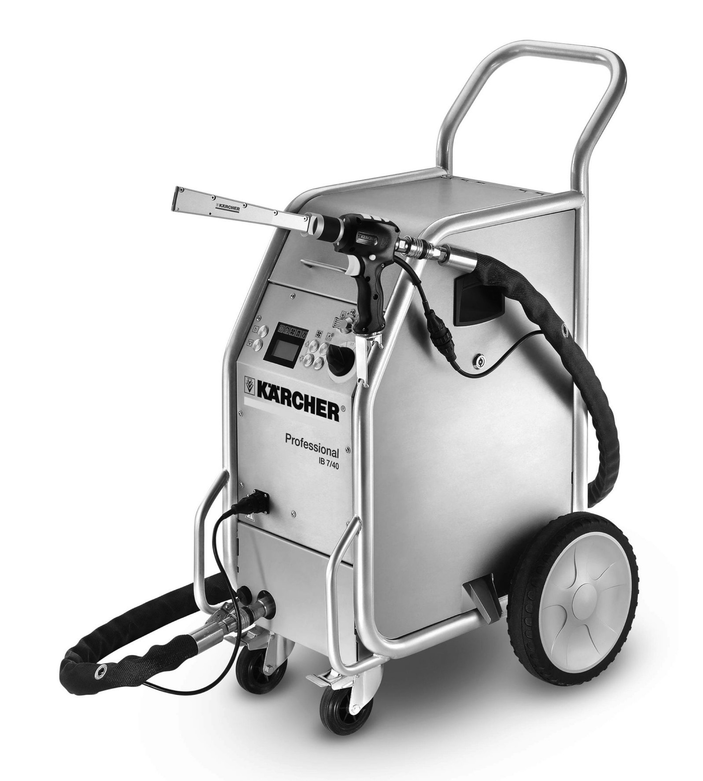
IB 7/40 Classic IB 7/40 Advanced
59629020 (10/24)
59629020 (10/24)
 Read the original instructions before using the device for the first time and act in accordance with it. Keep the original instructions for future reference or for future owners.
The device is used to remove dirt with dry ice pellets that are accelerated by an air jet.
The device may not be operated in a potentially explosive atmosphere.
Use only dry ice pellets as jet medium. Using any other jet medium can cause damage to the device.
The air pressure reaches the jet pistol via a pressure regulation valve. The valve opens when the trigger of the jet pistol is pressed and the air flow comes out from the jet pistol. Dry ice pellets are additionally dosed into the air jet via a dosing device.
With the version "IB 7/40 Advanced" the additional dosing can be switched off at the jet pistol.
The dry ice pellets hit the surface to be cleaned and remove the dirt. The -79 °C cold dry ice pellets also create thermal stresses between the dirt and the object to be cleaned, which also contribute to the loosening of the dirt. In addition, the dry ice immediately turns into gaseous carbon dioxide when it hits the surface, thus taking up 700 times its volume. Dirt penetrated by the dry ice is blown away as a result.
During the spraying operation through the jet, a vibrator located on the dry ice container ensures continuous sliding of the dry ice pellets.
 The packing materials can be recycled. Please dispose of packaging in accordance with the environmental regulations.
 Electrical and electronic devices contain valuable, recyclable materials and often components such as batteries, rechargeable batteries or oil, which - if handled or disposed of incorrectly - can pose a potential danger to human health and the environment. However, these components are required for the correct operation of the device. Devices marked by this symbol are not allowed to be disposed of together with the household rubbish.
Current information on content materials can be found at: www.kaercher.de/REACH
The device may only be operated by persons who have read and understood these operating instructions. In particular, all safety instructions must be observed.
Store these operating instructions so that they are available to the operator at all times.
The operator of the unit must carry out a risk assessment on site and ensure that operators are instructed.
Indication of an imminent threat of danger that will lead to severe injuries or even death.
Indication of a potentially dangerous situation that may lead to severe injuries or even death.
Indication of a potentially dangerous situation that may lead to minor injuries.
Indication of a potentially dangerous situation that may lead to damage to property.
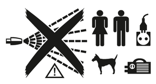 Danger from flying dry ice pellets.
Do not point the jet gun at people. Remove third parties from the operating location and keep them away ( e.g. by barriers) during operation. Do not touch the nozzle or the dry ice jet during operation.
 Risk of suffocation from carbon dioxide.
The dry ice pellets consist of solid carbon dioxide.
During operation, the carbon dioxide content of the air at the workplace increases.
Make sure there is sufficient air exchange at the workplace.
Lay the exhaust hose outdoors, for example, so that nobody is endangered by carbon dioxide.
Note: Carbon dioxide is heavier than air. Make sure that carbon dioxide does sink to lower-lying areas, for example by flowing from the outside into a basement below the workshop (flows).For longer jet work (longer than 10 minutes per day) and especially in small rooms (less than 300 m³), we recommend wearing a carbon dioxide warning device.
Signs of high levels of carbon dioxide:
In 3...5% of cases: Headache, high breathing rate.
In 7...10% of cases: Headache, nausea, possibly unconsciousness.
If these symptoms occur, switch off the device immediately and get some fresh air. Before continuing work, improve ventilation or use a breathing apparatus.
Carbon dioxide is heavier than air and collects in confined spaces, lower-lying spaces or in closed containers. Ensure adequate ventilation at the workplace.
Observe the safety specifications of the manufacturer of dry ice.
 Risk of injury, risk of damage from electrostatic charging.
The cleaning object can become electrostatically charged during the cleaning process.
Ground the object to be cleaned and keep it grounded it until the cleaning process is complete.
Risk of injury from electric shock.Pull the mains plug out of the socket before opening the control cabinet.
 Risk of injury from cold burns.
Dry ice has a temperature of -79 °C. Do not touch dry ice or cold parts of the device.
 Risk of injury from flying dry ice pellets and dirt particles.
Wear safety goggles.
Danger of hearing damage.Wear hearing protection.
 Risk of injury from flying dry ice pellets and dirt particles.
Wear protective gloves according to EN 511.
 Risk of injury from flying dry ice pellets and dirt particles.
Wear long-sleeved protective clothing.
Risk of injury
The device may start up unexpectedly.
Unplug the mains plug from the power socket before working on the device.Risk of injury
Dry ice and cold device parts can cause cold burns on contact with the skin.
Wear cold protection clothing or allow the device to warm up before working on the device.Never put dry ice in your mouth.Risk of injury
Light objects can be blasted away by the dry ice jet.
Fix light objects in place before starting cleaning.Risk of injury
The recoil force of the jet gun can throw you off balance.
Find a safe place to stand and hold the jet gun firmly before you pull the trigger.Risk of injury
Dry ice pellets and dirt particles can hit and injure people.
Do not use the device when other people are within range unless they are wearing protective clothing.Risk of injury
Do not use the device if a power cable or important parts of the device are damagede.g. safety devices, abrasive hose, jet gun.Danger of crushing on account of the dosing equipment.
Always remove the device's mains plug from the socket before removing the protective shield of the dry ice container.Special regulations and guidelines for handling dry ice blasting equipment may apply to the operation of this system.
It is therefore essential that you observe the regulations and guidelines applicable in your country and act accordingly!
Risk of injury due to missing or modified safety devices!
Safety devices are provided for your own protection.
Do not bypass, remove or render ineffective any safety devices.The Ice Blaster has an emergency stop button. If the button is pressed, the dry ice dosing is stopped and the airflow from the nozzle is interrupted.
Release the trigger of the jet gun.
Press the emergency off button.
The dry ice dosing is topped and the air flow from the nozzle is interrupted.
Shut off the compressed air supply.
Only use original accessories and original spare parts. They ensure that the appliance will run fault-free and safely.
Information on accessories and spare parts can be found at www.kaercher.com.
Check the contents for completeness when unpacking. If any accessories are missing or in the event of any shipping damage, please notify your dealer.
The warranty conditions issued by our relevant sales company apply in all countries. We shall remedy possible malfunctions on your appliance within the warranty period free of cost, provided that a material or manufacturing flaw is the cause. In a warranty case, please contact your dealer (with the purchase receipt) or the next authorised customer service site.
Further information can be found at: www.kaercher.com/dealersearch
Further warranty information (if available) can be found in the service area of your local Kärcher website under "Downloads".
*Only IB 7/40 Advanced
Risk of injury
Dry ice pellets can escape from damaged components and cause injuries.
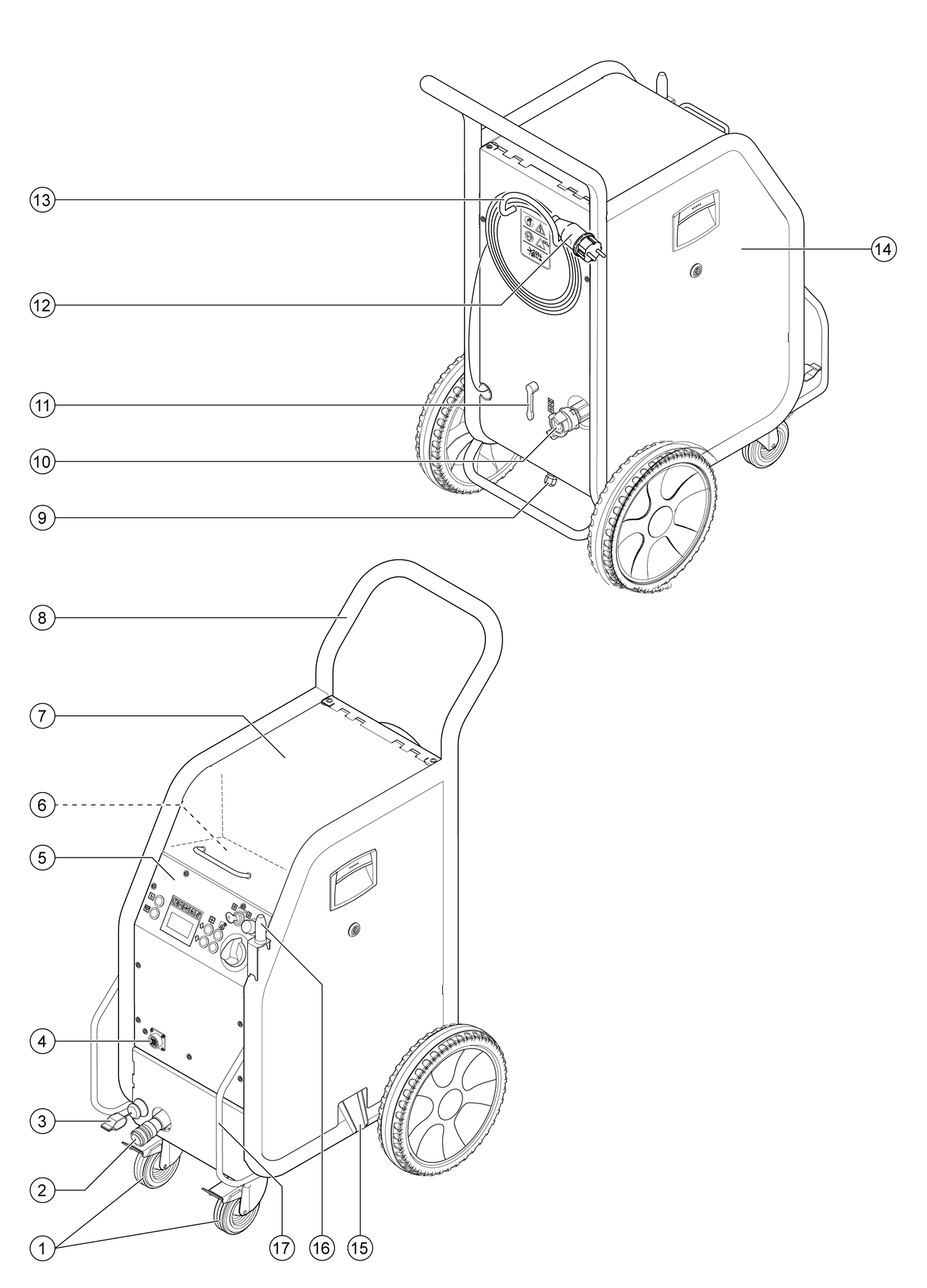
Before initial startup, check all components of the device, especially the abrasive hose, to ensure that they are in good condition. Replace damaged assemblies with flawless ones. Clean soiled assemblies and check that they are working properly.Store the device on a level and flat surface.
Block the steering rollers with the parking brakes.
Connect the spray agent hose to the device and secure it.
Connect the jet pistol to the device and secure it.
Connect the control cable to the device.
Connect the control cable to the jet pistol.
The choice of the nozzle depends on the material of the object to be cleaned and the contamination.
All nozzles can be screwed on top of the threading of the jet pistol without using any tools.
The threaded surfaces on the nozzle are to be used to loosen tight nozzles using a spanner.
Danger of injury due to the device being started unintentionally
Switch off the device before switching the nozzles.Risk of injury due to touching the cold nozzle
Warm up the nozzle before touching it or wear protective gloves.Cold welding
Smear the enclosed grease on the nozzle threading before installing it.In addition to the supplied flat stream nozzle, further flat and round stream nozzles in various designs are available as accessories.
Place the nozzle onto the threaded support of the jet pistol and tighten it by hand.
The scrambler crushes the dry ice pellets and is attached between the jet pistol and the nozzle. The alignment of the 4 holes plates in the scrambler indicates the degree of shredding.
Select the degree of shredding:
Unscrew the screw connection.
Remove the magazine with the perforated plates.
Align the hole plates in the magazine (3 possibilities). The above specifications in the illustration refer to the size of the permeation openings.
Insert the magazine with hole plates into the scrambler.
Unscrew the screw connection and tighten it.
Insert the nozzle extension between the jet pistol and nozzle.
Attach the handle to the extension.
Attach the working light between the nozzle and jet pistol.
Switch the working light on and off. Standard settings
For trouble-free operation, the compressed air must have a low moisture content (maximum 5% relative humidity, dew point below 0°C). The compressed air must be free of oil, dirt and foreign bodies.
The compressed air must be dry and oil-free, at least one aftercooler and a separator must be connected downstream of the compressor.
Close pressure relief valve.
Connect the compressed air inlet pipe to the compressed air connection point of the device. The maximum permissible supply pressure of 1 MPa (10 bar) must not be exceeded.
Risk of injury from electric shock
The power socket used must be installed by an electrician and comply with IEC 60364-1.The device may only be connected to a voltage supply with protective earth.The power socket used must be easily accessible and at a height of between 0.6 m and 1.9 m above the floor.The power socket used must be within sight of the operator.The device must be protected by an error current circuit breaker, 30 mA.Check the mains connection of the device for damage before each use. Do not operate the device with a damaged power cable. Have a damaged cable replaced by a qualified electrician.The extension cable must ensure IPX4 protection and the cable design must at least comply with H 07 RN-F 3G1.5.Unsuitable extension cables can be dangerous. If an extension cable is used, it must be suitable for outdoor use and the connection must be dry and above the ground. It is recommended to use a cable drum that holds the socket at least 60 mm above the floor.Plug the mains plug into the socket.
Cold burns
Dry ice has a temperature of -79 °C.
Never touch dry ice or cold parts of the machine without appropriate protection.Wear protective gloves and protective overalls.During longer breaks in operations, the dry ice pellets can melt in the dry ice container. As far as possible, do not interrupt operations for more than 20 minutes. If the device is to remain idle for a longer time, operate the device until the dry ice container is empty or empty the container via the dry ice emptying function.
Open the cover of the dry ice container.
Check the dry ice container for presence of foreign particles and condensate, remove them if found.
Fill dry ice pellets into the container.
Damage to the appliance due to unsuitable spray agent
Use only dry ice pellets as a spray agent.Close the cover of the dry ice container.
The settings depend on the substances contained in the detergent and the type of dirt.
Unlock the emergency stop button by pulling it.
Set the power switch to "I".
Turn the keyswitch in a clockwise direction.
Increase/ reduce the jet pressure by using the respective keys.
The higher you set the jet pressure, so much greater (more aggressive) will the cleaning effect be.
Increase/ reduce the dry ice dosing by using the respective keys.
Turn the keyswitch counter-clockwise and remove the key.
The automatic closure of the key hole will prevent contamination during operation.
When the key is removed, the device is protected against changes to the settings and resetting the statistics values.
Maintenance work must be carried out daily "before the start of operation". Care and service.
Risk of injury due to flying dry ice pellets
Do not point the jet pistol at people.Remove third parties from the operating location and keep them away during operation (e.g. through barriers).Do not touch the nozzle opening or the dry ice jet during operation.Before disconnecting the connection between the jet pistol and the media hose, as well as between the media hose and the device, ensure that the compressed air supply is shut off, the device is depressurised, and the mains plug is unplugged from the mains socket.Risk of suffocation from carbon dioxide
The dry ice pellets consist of solid carbon dioxide. The carbon dioxide content of the air at the workplace increases when the device is operated.
Signs of high carbon dioxide concentration in the air you breathe are headaches and high respiratory rate (carbon dioxide concentration 3...5 %) or headaches, nausea and unconsciousness (carbon dioxide concentration 7...10 %). If any of these symptoms occur, please switch off the device immediately and get a breath of fresh air; improve the ventilation before starting work again with the machine or use respirators.
Ensure that the workplace is adequately ventilated and use a personal warning device if necessary.Observe the safety specifications of the manufacturer of dry ice.Health risk due to harmful substances
Take appropriate safety measures before starting work if hazardous dust may be generated during processing.Risk of explosion
Simultaneous processing of light metals and ferrous parts can create explosive atmospheres.
Never work on light metals and ferrous parts at the same time.If you alternate between working on light metals and iron-containing parts, the work area and the suction device must be cleaned between work cycles.Electric shock due to electrostatic charging of the cleaning object and risk of damage to electronic assemblies
The object being cleaned can get charged electrically during the cleaning process.
Electrically ground the object to be cleaned and maintain it during the entire cleaning process.Risk of injury due to tripping
Lay the spray agent hose and control cable in a way that they do not pose a risk of stumbling during work.Damage caused by foreign objects falling into the dry ice container.
Keep the lid of the dry ice container closed during operationDamage to the dosing unit due to dirt
Keep the lid of the dry ice container closed during the operation to prevent sprayed off dirt from entering it.With model IB 7/40 Advanced, the dosing of dry ice pellets can be switched on or off via the key dry ice dosing on/off on the jet pistol. When the dosing is turned off, the key illuminates red, the display shows "ice off".
In addition, with the IB 7/40 Advanced model, the jet pressure and the dry ice volume can be changed on the jet pistol.
When using the jet pistol Advanced (Option), the dosing of dry ice pellets can be switched on or off via the key dry ice dosing on/off on the jet pistol. When the dosing is turned off, the key illuminates red, the display shows "ice off".
In addition, with the jet pistol Advanced, the jet pressure and the dry ice volume can be changed on the jet pistol.
Daily maintenance work was carried out before the start of operation" (see chapter Care and service).
Cordon off the work area to prevent people from entering during operation.
When working in confined spaces, ensure that there is sufficient air exchange to keep the carbon dioxide concentration in the room air below the dangerous level.
Attach the object to be cleaned if necessary.
Connect the grounding cable (with IB 7/40 Advanced only) electrically conductive with the cleaning object or ground the cleaning object in a different way.
Set the operating type for the compressed air jet to "1" or dry ice jet to "2" on the operating type switch of the jet pistol.
Wear protective clothing, protective gloves, tightly fitting safety goggles and hearing protection.
Activate the compressed air supply.
Unlock the emergency stop button by pulling it.
Choose a safe place to stand, assume a secure body stance to avoid being thrown off-balance by the recoil pressure of the jet pistol. In order to prevent the sudden recoil, a gradual increase of the jet pressure can be set up (see Chapter Standard settings.
Press the safety knob of the jet pistol.
Activate the dry ice jet by pressing the trigger of the jet pistol and carry out the cleaning operation.
Release the trigger of the jet gun.
Press the emergency off button.
The dry ice dosing is topped and the air flow from the nozzle is interrupted.
Interrupt the compressed air supply.
Release the emergency stop button by turning.
During longer breaks in operations, the dry ice pellets can melt in the dry ice container. As far as possible, do not interrupt operations for more than 20 minutes. If the device is to remain idle for a longer time, operate the device until the dry ice container is empty or empty the container via the dry ice emptying function.
Release the trigger of the jet pistol.
During breaks in operation, you can insert the jet pistol on the holder on the machine if necessary.
A water separator cleans the compressed air flowing to the device. This collects condensate in the water separator, that needs to be drained once in a while.
Place a catch pan under the condensate drain screw.
Open the pressure relief valve slowly and wait until the condensate has been drained from the device.
Dispose of the old condensate in accordance with the environmental regulations.
Set the power switch to "I".
Press the Statistics button briefly.
The operation duration is displayed.
t: Operation duration since the last reset
D: Total operating duration
Press the Statistics button briefly.
The processed dry ice amount is displayed.
m: Dry ice volume since the last reset
M: Total dry ice volume
Press the Statistics button briefly.
The average dry ice consumption is displayed.
q: Average dry ice consumption since the last reset
Q: Average total dry ice consumption
Turn the keyswitch in a clockwise direction.
Press the Statistics button for 4 seconds.
The values are reset.
The total values cannot be erased.
In the operating mode basic settings, the keys have the following functions:
Call up the standard settings menu.
Press and hold the Increase jet pressure and Decrease jet pressure button simultaneously.
Turn the keyswitch in a clockwise direction.
Configure the standard settings.
Menu item | Setting range | Description |
|---|---|---|
Soft start | 0, 1, 2, 3, 4, 5 seconds | Soft start, duration until the selected jet pressure is reached |
T_Dump | 1, 2, 3, 4, 5 minutes | Duration of the dry ice emptying process |
Language | metric, imperial | Measurement units metric: kg/h, MPa imperial: lbs, psi |
Lighting | ON/OFF | Switch the nozzle lighting (option) on/off |
Demo mode | ON/OFF | Demo mode: The operation is simulated, compressed air and dry ice dispensing is locked. |
Turn the keyswitch anti-clockwise to exit the standard settings menu.
Risk of injury due to flying dry ice pellets
Do not point the jet pistol at people.Remove third parties from the operating location and keep them away during operation (e.g. through barriers).Cold burns
Dry ice has a temperature of -79 °C.
Never touch dry ice or cold parts of the machine without appropriate protection.Wear protective gloves and protective overalls.Close the compressed air supply.
Place a catch pan under the condensate drain screw.
Open the pressure relief valve slowly and wait until the condensate and the compressed air have been drained from the device.
Dispose of the old condensate in accordance with the environmental regulations.
Place a catch pan under the dry ice outlet.
Press the key Empty dry ice container and wait until the dry ice container is empty.
The dry ice emptying stops after the preset time has elapsed (see Chapter Standard settings).
If needed, press the key Empty dry ice container several times.
Set the trigger to "0/OFF".
Disconnect the device from the compressed air supply line.
Pull the mains plug out of the outlet.
Clean and roll up the grounding cable.
Dispose of blasting debris according to applicable regulations.
Risk of accident on account of dry ice residue in the device
In closed vehicles, carbon dioxide from melting dry ice can endanger people travelling in the vehicle.
Remove all dry ice from the device before transport.Risk of injury or damage due to non-observance of the weight!
When transporting and storing the device, there is a risk of injury and damage due to its weight.
Take into account the weight of the device for transportation and storage, see chapter Technical data.Carry out all the steps in the Chapter "Ending operation" (Ending operation) before transport.
Mount the appliance on the transport vehicle.
Lock the brakes on the steering rollers.
Secure the device with lashing straps.
Risk of suffocation due to accumulation of carbon dioxide
Only store dry ice pellets in areas that are well ventilated.Risk of injury or damage due to non-observance of the weight!
When transporting and storing the device, there is a risk of injury and damage due to its weight.
Take into account the weight of the device for transportation and storage, see chapter Technical data.Only store the device indoors.
Regular maintenance according to the following maintenance plan is fundamental for a safely operating system.
Use only original manufacturer spare parts or parts recommended by the original manufacturer, such as
Spare parts and wearing parts,
Accessories,
Operating materials,
Detergent.
Danger of accident
The device can start unintentionally. Cold unit parts or liquid carbon dioxide can cause frostbite. Gaseous carbon dioxide can cause death by asphyxiation.
Before working on the device, carry out all the steps in the "Ending operation" chapter. Wait until the device has warmed up or wear cold protection clothing. Never put dry ice in your mouth.Risk of damage
Using the wrong detergent can damage the device and the jet gun.
Never clean the device or the jet gun with solvents, petrol or detergents containing oil.We recommend that you close a service contract to ensure reliable operation of the system. Please contact your KÄRCHER customer service department responsible.
Carefully examine the abrasive hose for cracks, kink points and other damage. Soft spots in the hose indicate wear on the inside of the hose. Replace the defective or worn hose with a new hose.
Examine electrical cables and plugs for damage. Have defective parts replaced by Customer Service.
Check the couplings on the abrasive hose and on the device for damage and wear. Replace a defective spray agent hose, have defective couplings on the device replaced by Customer Service.
Check dosing equipment for damages or leaks. Have damage or leaks repaired by Customer Service.
Check the attachment caps of the rear wheels for proper seating.
Have the device checked by Customer Service.
The side panels of the device must be removed to access the device for maintenance jobs.
Turn the snap closure counter-clockwise.
Remove side panel.
Remove the 4 screws.
Remove the lower part.
Remove the nut.
Remove the washer.
Remove the filter insert.
Insert a new filter insert.
Reassemble the water separator in the reverse sequence.
According to DGUV R 100-500, the following tests must be carried out on the unit by an expert. The results of the test must be recorded in a test certificate. The operator of the device must keep the test certificate until the next test.
Check the device for correct condition and function.
Check the device for proper condition, function and installation.
Check the device for proper condition, function and installation.
Danger of accident
The device can start unintentionally. Cold device parts or liquid carbon dioxide can cause frostbite. Gaseous carbon dioxide can cause death by asphyxiation.
Before working on the device, carry out all the steps in the "Ending operation" chapter. Wait until the device has warmed up or wear cold protection clothing. Never put dry ice in your mouth.Risk of damage
Using the wrong detergent can damage the device and the jet gun.
Never clean the device or the jet gun with solvents, petrol or detergents containing oil.Malfunctions often have simple causes that you can remedy yourself using the following overview. When in doubt, or in the case of malfunctions not mentioned here, please contact your authorised Kärcher Customer Service.
E001
Indicator lamp of control voltage lights up red
Cause:
Control voltage is too low.
Remedy:
Operator
Switch off the device.
Wait for a short time.
Switch the device on again.
Remedy:
Operator
Have the socket checked.
If this error recurs, please contact the Kärcher customer service department.
E002
Indicator light of emergency STOP lights up red
Cause:
Emergency-stop button has been pressed.
Remedy:
Operator
Unlock the emergency stop button by pulling it.
E003
Indicator light of compressed air lights up red
Cause:
Pressure of the compressed air supply too low.
Remedy:
Operator
Increase the pressure.
Switch off the device.
Wait for a short time.
Switch the device on again.
E004
Indicator light of dosing lights up red
Cause:
Interference in the dosing.
Remedy:
Operator
Switch off the device.
Wait for a short time.
Switch the device on again.
Remedy:
Operator
If this error recurs, please contact the Kärcher customer service department.
E005
Indicator light of jet pistol lights up red
Cause:
Connection between the device and the jet pistol is faulty.
Remedy:
Operator
Check for correct connection of the couplings in the control line.
Check the control cable for damage.
E006
Indicator light of jet pistol lights up red
Cause:
Short in jet pistol or control cable.
Remedy:
Operator
Replace the jet pistol or the jet hose with a control cable.
E007
Indicator light of compressed air lights up red
Cause:
Fault in the compressed air regulator valve.
Remedy:
Operator
Call Customer Service.
E008
Indicator light of jet pistol lights up orange
Cause:
The trigger of the jet pistol was pressed during the power-up or when releasing the emergency stop button.
Remedy:
Operator
Release the trigger of the jet pistol.
No display despite main switch being switched on
Cause:
The mains plug is not plugged into the socket.
Remedy:
Operator
Plug the mains plug into a mains socket.
Cause:
Fuse F1 has tripped.
Remedy:
Operator
Remove the side panel and unlock the fuse F1 by pressing on it.
No compressed air jet despite the trigger being drawn
Cause:
Compressed air supply has too little pressure.
Remedy:
Operator
Check the pressure.
Cause:
Jet pressure is set too low.
Remedy:
Operator
Set the jet pressure to a higher level.
Cause:
Voltage supply has been interrupted.
Remedy:
Operator
Check voltage supply. Indicator lamp "Device on" must glow green.
Cause:
Emergency-stop button has been pressed.
Remedy:
Operator
Unlock the emergency stop button by pulling it. Indicator lamp "Device on" must glow green.
Cause:
Control cable is not connected properly.
Remedy:
Operator
Check the connection between control cable and the jet pistol and between the control cable and the device.
Cause:
Control cable is defective.
Remedy:
Operator
Replace spray agent hose.
Compressed air jet is too weak
Cause:
Jet pressure is set too low.
Remedy:
Operator
Set the jet pressure to a higher level.
Cause:
Compressed air supply has too little pressure or the compressor output is too low.
Remedy:
Operator
Check the pressure and output.
Cause:
The filter insert in the water separator is plugged.
Remedy:
Operator
Replacing the filter insert in the water separator.
Cause:
Spray agent hose or jet pistol is blocked.
Remedy:
Operator
Allow the spray agent hose and jet pistol come to room temperature and remove the blocking.
Increase the working pressure and / or reduce the dry ice dosing.
No dry ice pellets in the compressed air jet
Cause:
Dry ice dosing is switched off (only with blasting gun Advanced). The "Dry ice dosing on/off" button on the jet pistol illuminates red, display shows "Ice off".
Remedy:
Operator
Press the dry ice dosing key on the jet pistol.
Cause:
Dry ice container is empty.
Remedy:
Operator
Refill the dry ice container.
Cause:
Dry ice has melted.
Remedy:
Operator
Empty the dry ice container and refill it with fresh dry ice pellets.
Cause:
Vibrator on the dry ice container is not working.
Remedy:
Operator
Consult the Customer Service.
Cause:
The drive motor of the dosing device is overloaded.
Remedy:
Operator
Let the dosing equipment thaw.
Cause:
Compressed air is exiting into the dry ice container.
Remedy:
Customer Service department
Clean the pressure balance channel in the dosing equipment.
Cause:
Dosing disc in the dosing unit is defective
Remedy:
Customer Service department
Replace the dosing disc.
Electrical connection | |
Mains voltage | 220...240 V |
Phase | 1 ~ |
Frequency | 50 Hz |
Power rating | 0,6 kW |
Leakage current, typical | <7,5 mA |
Residual current device | 0,03 delta I, A |
Compressed air connection | |
Compressed air hose, nominal width | 1/2 Inches |
Pressure (max.) | 1,0 (10) MPa (bar) |
Pressure (min.) | 0,2 (2) MPa (bar) |
Compressed air consumption | 0,5…3,5 m3/min |
Quality of compressed air | dry and oil-free, at least 1 aftercooler and 1 separator are installed downstream |
Device performance data | |
Jet pressure, max. | 1,0 (10) MPa (bar) |
Diameter of dry ice pellets (max.) | 3 mm |
Dry ice consumption | 15…50 kg/h |
Dimensions and weights | |
Contents of dry ice container | 15 kg |
Width | 510 mm |
Depth | 768 mm |
Height | 1096 mm |
Net weight, without accessories | 70 kg |
Operating weight | 93 kg |
Weight of the jet equipment (spray agent hose, jet pistol, tool case) | 6,75 kg |
Recoil force of the jet gun, max. | 30 N |
Abrasive hose | 8 N |
Unit vibrations | |
jet pistol | 1,2 m/s2 |
Abrasive hose | 1,2 m/s2 |
Electrical connection | |
Mains voltage | 220...240 V |
Phase | 1 ~ |
Frequency | 50 Hz |
Power rating | 0,6 kW |
Leakage current, typical | <7,5 mA |
Residual current device | 0,03 delta I, A |
Compressed air connection | |
Compressed air hose, nominal width | 1/2 Inches |
Pressure (max.) | 1,0 (10) MPa (bar) |
Pressure (min.) | 0,2 (2) MPa (bar) |
Compressed air consumption | 0,5…3,5 m3/min |
Quality of compressed air | dry and oil-free, at least 1 aftercooler and 1 separator are installed downstream |
Device performance data | |
Jet pressure, max. | 1,0 (10) MPa (bar) |
Diameter of dry ice pellets (max.) | 3 mm |
Dry ice consumption | 15…50 kg/h |
Dimensions and weights | |
Contents of dry ice container | 15 kg |
Width | 510 mm |
Depth | 768 mm |
Height | 1096 mm |
Net weight, without accessories | 71 kg |
Operating weight | 95 kg |
6,75 kg | |
Recoil force of the jet gun, max. | 30 N |
Abrasive hose | 8 N |
Unit vibrations | |
jet pistol | 1,2 m/s2 |
Abrasive hose | 1,2 m/s2 |
We hereby declare that the machine described below complies with the relevant basic safety and health requirements in the EU Directives, both in its basic design and construction as well as in the version placed in circulation by us. This declaration is invalidated by any changes made to the machine that are not approved by us.
Product: Ice Blaster
Type:
1.574-xxxCurrently applicable EU Directives2006/42/EC (+2009/127/EC)
2014/30/EU
2011/65/EU
2009/125/EC
Commission Regulation(s)(EU) 2019/1781
Harmonised standards usedEN 60335-1
EN IEC 63000: 2018
EN 62233: 2008
EN 55014-1: 2017 + A11: 2020
EN 55014-2: 1997 + A1: 2001 + A2: 2008
EN 61000-3-2: 2014
EN 61000-3-3: 2013
The signatories act on behalf of and with the authority of the company management.

Documentation supervisor:
S. Reiser
Alfred Kärcher SE & Co. KG
Alfred-Kärcher-Str. 28 - 40
71364 Winnenden (Germany)
Ph.: +49 7195 14-0
Fax: +49 7195 14-2212
Winnenden, 2024/03/01
4-2-SC-A4-GS-17339