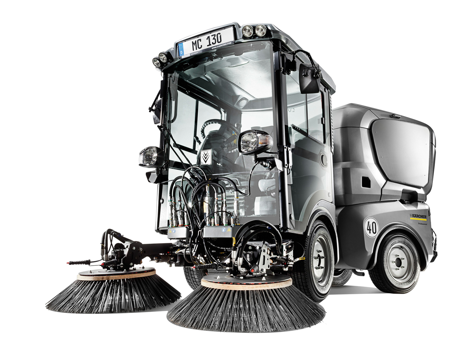
MC 130 Plus
59687170 (03/21)
59687170 (03/21)
 Read the original instructions and the safety instructions before using your vehicle for the first time. Act in accordance with them.
Keep these operating instructions for future reference or for future owners.
Please report any defects or shipping damage identified on the vehicle when it is handed over directly to your dealer or department store.
Device carrier with Kubota 48 kW engine
Version with diesel particle filter
All-wheel drive (4WD)
Can be used as a vacuum sweeper with optional sweeper attachment
Vacuum sweeper with 48 kW Kubota engine
Version with diesel particle filter
All-wheel drive (4WD)
The warranty conditions issued by our relevant sales company apply in all countries. We shall remedy possible malfunctions on your appliance within the warranty period free of cost, provided that a material or manufacturing defect is the cause. In a warranty case, please contact your dealer (with the purchase receipt) or the next authorised customer service site.
(See overleaf for the address)
The following versions of the vehicle are described in these operating instructions.
Kehrsaugmaschine MC 130 Plus / Geräteträger MC 130 Plus
The vehicle may only be used for the intended use, as illustrated and described in these operating instructions.
Intended use also includes adherence to the prescribed maintenance activities and intervals.
The vehicle and attachments may only be used, maintained and repaired by persons familiar with the vehicle and attachments and the associated hazards.
The legally applicable general safety and accident prevention regulations must be adhered to. All other safety regulations, occupational health care regulations and road traffic regulations must be adhered to.
The operating personnel must:
Be physically and mentally suitable.
Have been instructed in the handling of the vehicle and attachments.
Have read and understood these operating instructions and the operating instructions for any attachments or towed machinery prior to starting work.
Have provided the operating company with verification of capability to operate the vehicle.
Be explicitly nominated to operate the vehicle by the operating company.
The vehicle is a device carrier to which various attachments (not included in the scope of delivery) can be attached at the front and at the back, according to requirements.
This vehicle is suitable for use with various attachments as well as for pulling trailers.
The max. admissible trailing load is indicated on the type plate and must not be exceeded.
The device carrier is also intended for the use in agriculture and forestry, maintenance of grassed areas and public spaces as well as winter service.
The vehicle must meet the applicable national directives when operated on public roads.
Only attachments that have been approved by KÄRCHER may be used.
KÄRCHER does not assume any liability for accidents or malfunctions caused by attachments that have not been approved.
Observe the operating instructions for the relevant attachments.
This vehicle is a vacuum sweeper.
The vacuum sweeper is intended for cleaning dirty outdoor surfaces.
The vehicle must conform to the applicable national regulations if used on public roads.
The vehicle is only suitable for use on the surfaces listed in the operating instructions.
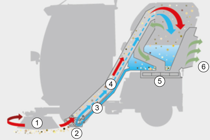
The dust created is bound by sprayed water.
The side brushes rotate inwards and convey the waste in front of the suction mouth.
The suction fan generates a vacuum and sucks the waste into the waste container.
The filtered exhaust gas escapes from the rear side of the waste container.
The dust is more effectively bound through the recycled water operation (water circulation).
Asphalt
Industrial floor
Screed
Concrete
Paving stones
Any type of improper use is prohibited.
The operating personnel are liable for hazards resulting from incorrect use. Using the vehicle for other purposes than those described in this documentation is prohibited.
No modifications must be made to the vehicle.
Never sweep/vacuum explosive liquids, inflammable gases or undiluted acids and solvents. These include petrol, paint thinners or heating oil, which can form explosive vapours or mixtures through suction air turbulence, also acetone, undiluted acids and solvents because these attack the materials used in the machine.
Never sweep or vacuum reactive metal dusts (e.g. aluminium, magnesium, zinc) because they form explosive gases in conjunction with highly alkaline or acidic cleaning agents.
Never sweep or vacuum burning or smouldering objects.
Do not remain in the hazard zone.
Never operate the vehicle in potentially explosive environments.
Never transport persons on the vehicle, the loading area or attachments.
Do not use the vehicle as a front loader.
Do not use the vehicle in the forestry industry.
Do not use the vehicle for dispersing insecticide, pesticide or fertiliser.
 The packing materials can be recycled. Please dispose of packaging in accordance with the environmental regulations.
 Electrical and electronic appliances contain valuable, recyclable materials and often components such as batteries, rechargeable batteries or oil, which - if handled or disposed of incorrectly - can pose a potential threat to human health and the environment. However, these components are required for the correct operation of the appliance. Appliances marked by this symbol are not allowed to be disposed of together with the household rubbish.
Current information on content materials can be found at: www.kaercher.com/REACH
Observe the national regulations at the location.
Observe company-specific specifications.
Dispose of any operating and auxiliary materials according to the valid safety data sheets.
Vehicles that are no longer fit for service contain valuable recyclable materials. We recommend you cooperate with a waste management company with regard to the disposal of your vehicle.
Indication of an imminent threat of danger that will lead to severe injuries or even death.
Indication of a potentially dangerous situation that may lead to severe injuries or even death.
Indication of a potentially dangerous situation that may lead to minor injuries.
Indication of a potentially dangerous situation that may lead to damage to property.
Risk of asphyxiation. Keep packaging film out of the reach of children.
Only use the vehicle for its proper use. Take into account the local conditions and beware of third parties, in particular children, when working.
Persons with reduced physical, sensory or mental capabilities, or those with a lack of experience and knowledge, are only allowed to use the vehicle if they are supervised or have been instructed with respect to using the appliance safely, and understand the resultant dangers involved.
Only people who have been instructed on how to use the vehicle, or have proven their ability to operate it, and have been explicitly instructed to use it, must use the vehicle.
Children must not operate the vehicle.
Children must be supervised to prevent them from playing with the vehicle.
Safety devices are provided for your own protection. Never modify or bypass safety devices.
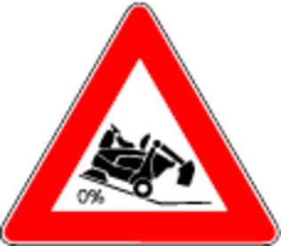
Danger of tilting if hill or slope is too steep! Observe the maximum permissible values in the technical data when driving up hills and slopes.
Danger of tilting in case of excessive tilting at side! Observe the maximum permissible values in the technical data when driving lateral to the travel direction.
Danger of tipping on unstable surfaces! Only use the vehicle on stable surfaces.
Risk of accident due to not adapting speed. Approach corners slowly.
The list on the risk of overturning is not necessarily comprehensive.
Driver cabins are equipped with air exit slats. Always keep these free from obstructions to ensure sufficient ventilation.
Ensure free visibility on public roads before use (e.g. fog-proof windscreens, mirrors, etc.).
Diesel engine: Never operate vehicles with diesel engines in confined spaces.
Danger of poisoning: Do not inhale the exhaust gases.
Never close off the exhaust gas openings.
Never bend down over the exhaust gas opening. Never reach inside the exhaust gas opening.
Always keep away from the drive area. Be aware of the engine after-running time after switching off (3-4 seconds).
Pay attention to the weight of the vehicle to avoid accidents and injuries, see Chapter Technical data.
Pay attention to the vehicle height during transport on a trailer or lorry and secure the vehicle, see Chapter Technical data.
Switch off the engine and remove the ignition key before performing cleaning or maintenance work on the vehicle, replacing parts or changing the functionality of the vehicle.
Repairs may only be carried out by approved customer service sites or staff qualified in this area who are familiar with all relevant safety instructions.
Adhere to the safety checks according to the applicable local regulations for mobile commercial vehicles.
The articulated joint, tyres, radiator fins, hydraulic hoses and valves, seals, electrical and electronic components must not be cleaned using a high-pressure cleaner.
The information in this chapter is also provided on a supplementary sheet that must always be carried on the vehicle.
The vehicle has a hydrostatic drive and articulated steering. It therefore exhibits driving characteristics that are different to those of a motorcar.
Danger of tipping over
Please note that the driving characteristics of a vehicle with articulated steering differ considerably from those of a motorcar.
Drive around curves at an even and appropriate speed. This applies, in particular, for driving uphill/downhill and driving across the face of a slope.
Be aware of the changes in the centre of gravity of the vehicle depending on attachments.
Adjust the travel speed to the ambient conditions when driving in a straight line and when driving around bends, e.g. road conditions and the load status.
Note decoupling of the front and rear part of the vehicle via a central pendulum joint.
Release the accelerator pedal provides a form of active braking. This differs from a motorcar where only the engine brake reduces vehicle speed.
The braking force applied when you release the accelerator pedal is weaker in higher gears and stronger in lower gears.
The braking force applied when you release the accelerator pedal in transport mode is significantly weaker than in working mode.
Vehicles with articulated steering exhibit a more direct response to steering movements than motorcars, particularly when taking bends at high speed, on snow, ice and wet/loose ground as well as during turning manoeuvres on slopes. Avoid rapid successive steering movements.
Centre of gravity / pendulum characteristicsRear attachments and load statuses influence the vehicle's centre of gravity and the driving characteristics. You must be ready to adjust to changed driving characteristics, particularly after changing attachments and in the case of changeable load statuses. Limit ranges may be reached earlier.
The vehicle has a central pendulum joint to provide a high degree of all-terrain mobility. This enables both vehicle halves to move transversely to the travel direction independently from one another.
This special property means that the driver does not receive immediate feedback on the behaviour of the rear half of the vehicle. You should therefore take care to use the mirrors to keep an eye on the rear of the vehicle.
Risk of injury on sweepers with high dumping
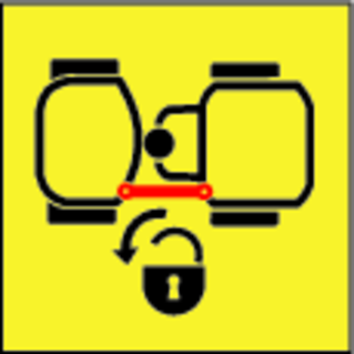
Secure the lifted waste container before working. Fit the retainer only from outside the hazard zone.
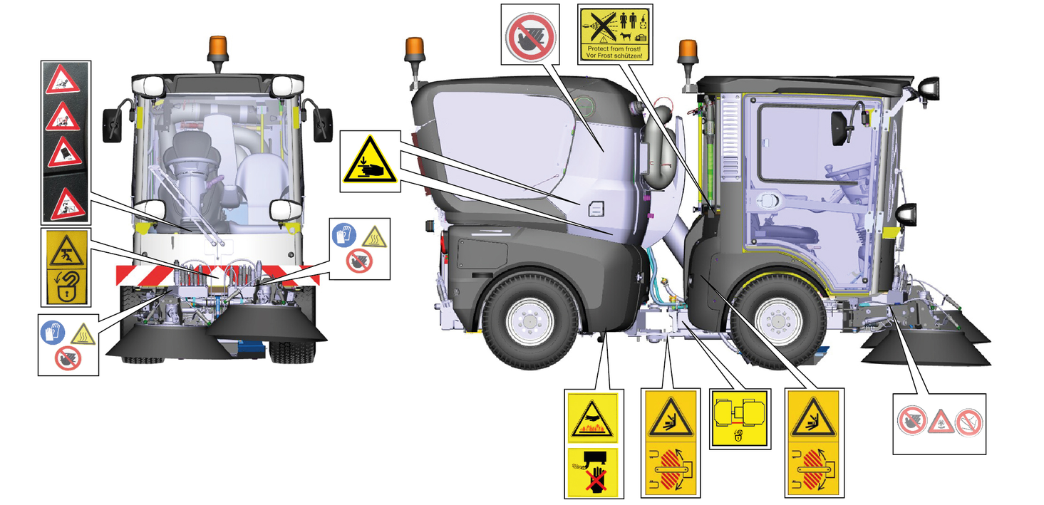
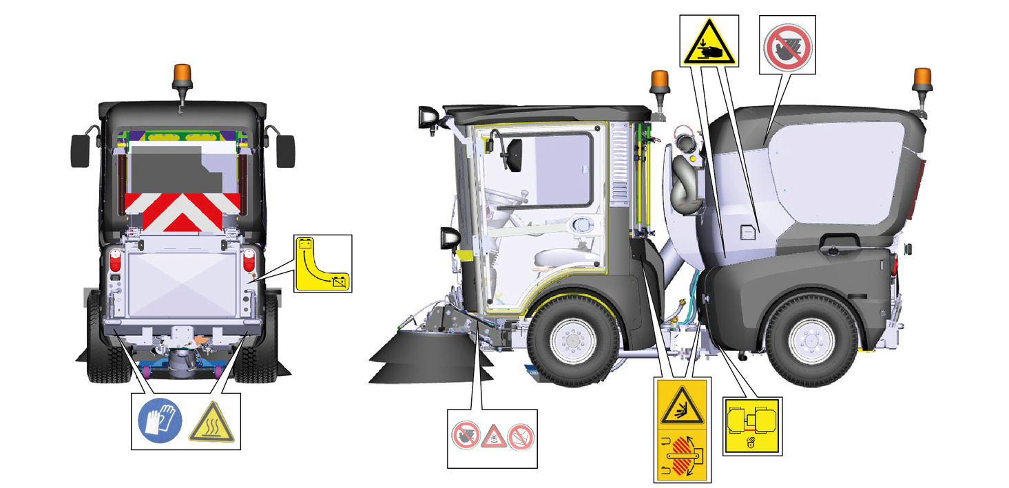
Replace the symbols immediately if they become illegible or get lost.
 | DANGERRisk of burns from hot surfaces Allow the vehicle to cool down before working on it. |
 | DANGERRisk of burns due to hot exhaust pipe Do not touch the exhaust pipe. Before working, allow the exhaust pipe to cool down. |
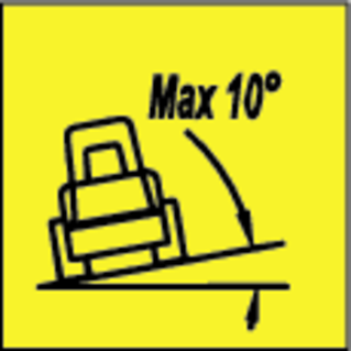 | DANGERDanger of tilting Only drive on terrain with a maximum lateral incline of 10°. |
 | DANGERRisk of injury on account of splashing objects Keep an adequate distance from persons, animals and objects. |
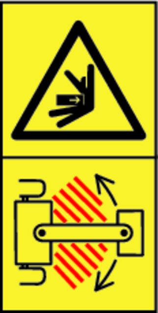
 | WARNINGRisk of injury Risk of being squeezed or hurt at the belts, side-brushes, waste container, cover. |
 | DANGERDanger of crushing Make sure that no persons are present in the vicinity of the articulated joint or vehicle during operation. When using the vehicle for towing, make sure that no persons are located during operation between vehicle and trailer. |
 | DANGERRisk of injury from rotating parts Open the bonnet only when the motor has come to a halt. |
 | ATTENTIONDamage from incorrect transport During the transport, place always the transport lock on the articulated joint. |
 | WARNINGHealth risk due to poisonous exhaust gases Do not inhale exhaust gases. |
 | DANGERRisk of injury due to unauthorised usage Remove the ignition key to protect against unauthorised use and prior to cleaning and maintenance work. |
 | ATTENTIONSafety for cleaning and maintenance Prior to cleaning and maintenance work, park the vehicle on a level and firm subsurface. |
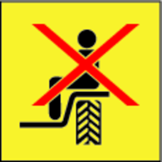 | DANGERDanger of injury due to use of unspecified locations for seating Sit exclusively on the driver’s seat. |
 | DANGERRisk of injury due to rolling over No persons may be present in the vicinity of the vehicle during use. |
 | DANGERRisk of impact, risk of crushing When transporting or working under suspended loads, use suitable means for supporting. |
 | DANGERDanger of tilting Only empty the waste container when the vehicle is placed on a level and firm subsurface. |
 | DANGERRisk of fire Do not sweep up burning or glowing objects such as cigarettes, matches or similar objects. |
 | DANGERRisk of crushing Keep your hands away from this area. |
 | Main switch (battery isolation switch) |
 | Lubrication point |
 | Lubricating strip |
 | Lashing point |
 | Quality of the brake fluid and position where brake fluid can be filled Position of container for brake fluid |
 | Locating point for a jack or a support |
 | Position of main fuse |
 | Position of fuse F2 |
 | Emergency exit |
 | Read operating instructions |
 | Wear protective gloves |
 | WARNINGRisk of injury from high-pressure jet Do not direct the high-pressure jet at persons, animals, live electrical equipment or at the device itself. Protect the device high-pressure cleaner frost. |
 | DANGERRisk of injury from rotating brushes Ensure that no persons are in the vicinity of the danger zone. |
 | ATTENTIONRisk of injury from the machine rolling away Always apply the parking brake when parking the machine. |
 | DANGERClimbing prohibited Tip the waste container only when nobody is in the hazard zone. |
 | DANGERTipping prohibited Attach the sweeper attachment only when in the operating position. |
 | ATTENTION
The machine drives only when the waste container is retracted. |
 | ATTENTIONClimbing prohibited Do not climb on the machine. |
 | WARNINGRisk of injury Tip the waste container only on a level surface. |
Immediately replace illegible or absent symbols.
Safety devices protect the user and may not taken out of operation or functionally circumvented.
Adhere to the safety instructions in the chapters!
The main switch interrupts the electrical supply line to the starter motor.
Always disconnect the battery after parking the vehicle (Battery disconnected position).
Prerequisites for starting the motor:
Main switch activated (position battery connected)
Driver is sitting on the driver’s seat
When the driver's seat is vacant:
The vehicle cannot be driven.
The front PTO cannot be switched on or off.
The parking brake requires hydraulic pressure to release.
The parking brake is therefore applied when the engine is switched off.
The parking brake is also applied when the engine is running and the travel direction lever is in the NEUTRAL position.
The "Parking brake applied" warning light in the multifunction display lights up when the parking brake is applied.
The operator is protected from lightning strikes when sitting in the driver cabin.
The driver cabin has a roll-over protection structure (ROPS), which prevents rolling over after tipping over.
The driver cabin does not have a structure providing protection from falling objects (FOPS).
The driver cabin does not have a structure providing protection from falling objects (OPS).
Always use the safety belt.
Only use the batteries and chargers recommended by the manufacturer
Only replace batteries with batteries of the same type.
Before disposing of the vehicle, remove the battery and dispose of it in accordance with national or local regulations.
Observe the following warnings when handling the batteries:
 | Observe notes in the instructions for the battery, on the battery and in these operating instructions. |
 | Wear eye protection. |
 | Keep acids and batteries away from children. |
 | Risk of explosion |
 | Fire, sparks, open flames and smoking are prohibited. |
 | Risk of acid burns |
 | First aid. |
 | Warning |
 | Disposal |
 | Do not throw batteries in the bin. |
Risk of fire and explosion
Do not place tools or other objects on the battery.
Naked flames and smoking must be strictly avoided.
Ensure the room is well ventilated when charging batteries.
Only use batteries and chargers approved by Kärcher (original spare parts).
Environmental risk due to improper disposal of batteries
Ensure that defect or used batteries are disposed of safely (contact a waste management company or Kärcher Service).
When used normally, and when observing the instructions, lead-acid batteries do not pose any risk.
However, keep in mind that lead-acid batteries contain sulphuric acid which can cause serious chemical burns and corrosion.
If there is spillage or, if the battery is leaking, acid is escaping, lay down a binding agent such as sand. Do not let it reach the sewer system, soil or a body of water.
Neutralise the acid with lime/baking soda and dispose of it according to local regulations.
Contact a waste management company to dispose of faulty batteries.
Rinse out your eyes or rinse off your skin with copious amounts of fresh water if acid splashes into your eyes or onto your skin.
Then consult a doctor immediately.
Wash any contaminated clothing with water.
Change clothes.


Definition of the term, hydraulic PTO
Power Take Off = hydraulic force output
Definition of the term, AUX
Auxiliary valve
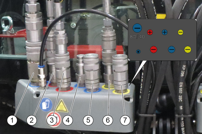
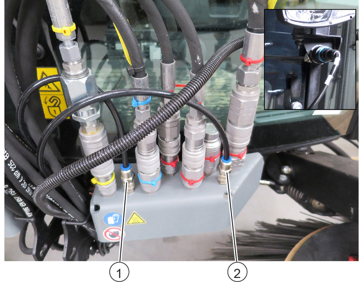
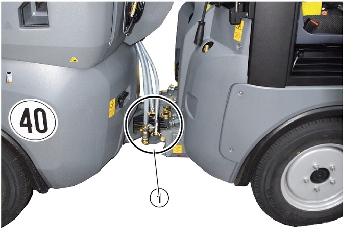
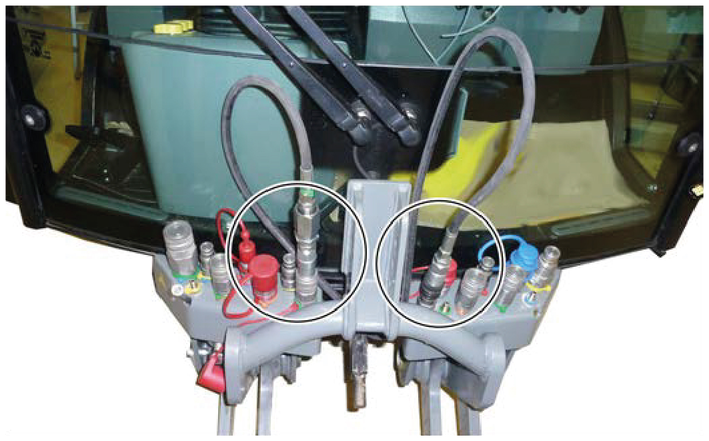
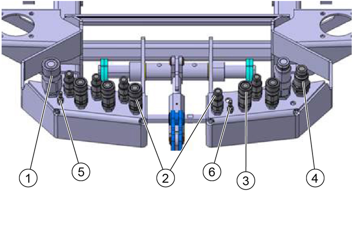
Right-hand side connections
Left-hand side connections
Right-hand side connections
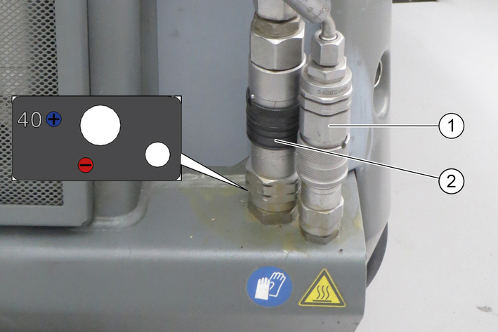
AUX hydraulic connection, raise/lower
Hydraulic PTO (40 l/min)
Left-hand side connections
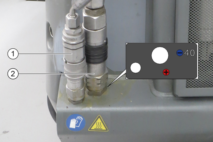
AUX hydraulic connection, raise/lower
Return line (40 l/min)
Terminology electric PTO
Power Take Off = electric power output

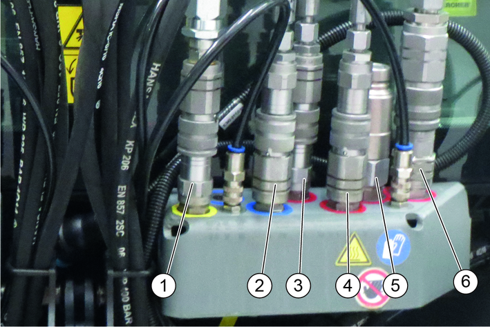
Right-hand side connections
Left-hand side connections
The main switch interrupts the electrical supply line to the starter motor.
If the main switch is pressed when the engine is running (battery disconnected), the engine will stop.
Always disconnect the battery when the vehicle is parked.
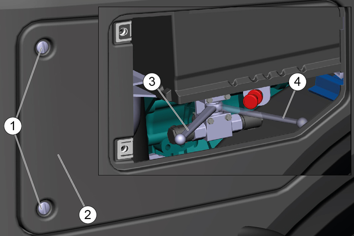
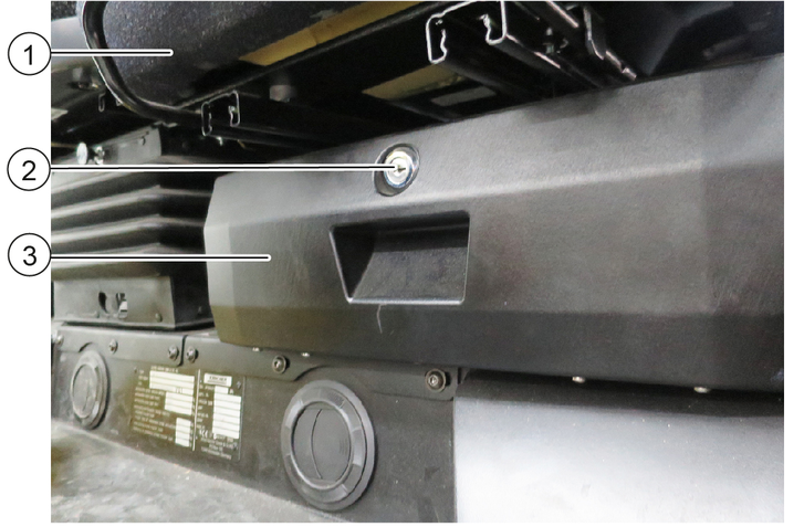
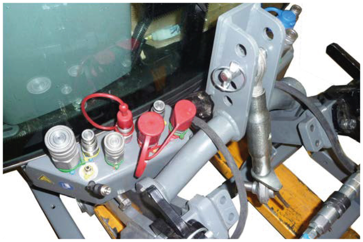
The emergency operation hydraulic valve is located under a cover behind the driver cabin.
A description of this is provided in chapter Troubleshooting guide.
This hydraulic valve is required when:
The waste container/attachment frame cannot be raised because the device hydraulics have failed. For example when the engine fails.
The front power lift/suction mouth cannot be raised because the device hydraulics have failed. For example when the engine fails.
The parking brake spring actuator cannot be released, e.g. for towing the vehicle.
There are two different versions of the switch lever depending on the version of the vehicle.
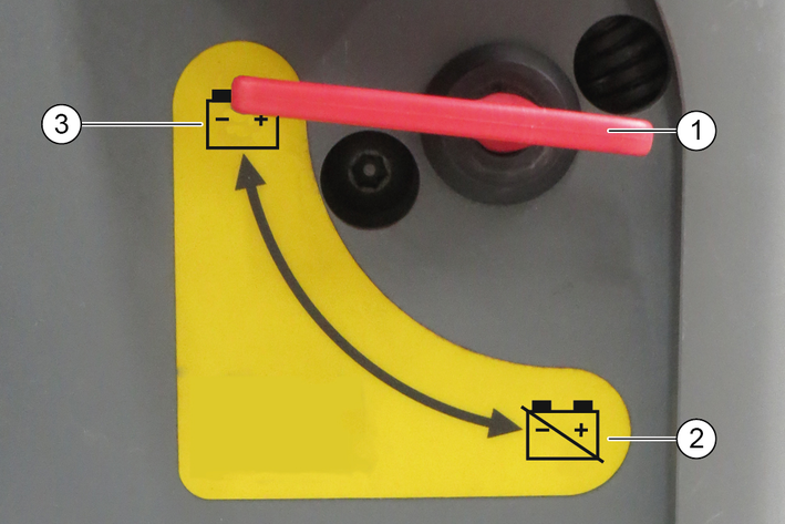
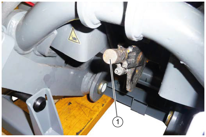
The hydraulic system can be switched between the waste container and attachment frame via the switchover valve.
The waste container and attachment frame are electronically monitored. Both functions cannot be activated simultaneously.
The hydraulic system can be switched between the waste container and attachment frame via the switchover valve.
The waste container and attachment frame are electronically monitored. Both functions cannot be activated simultaneously.
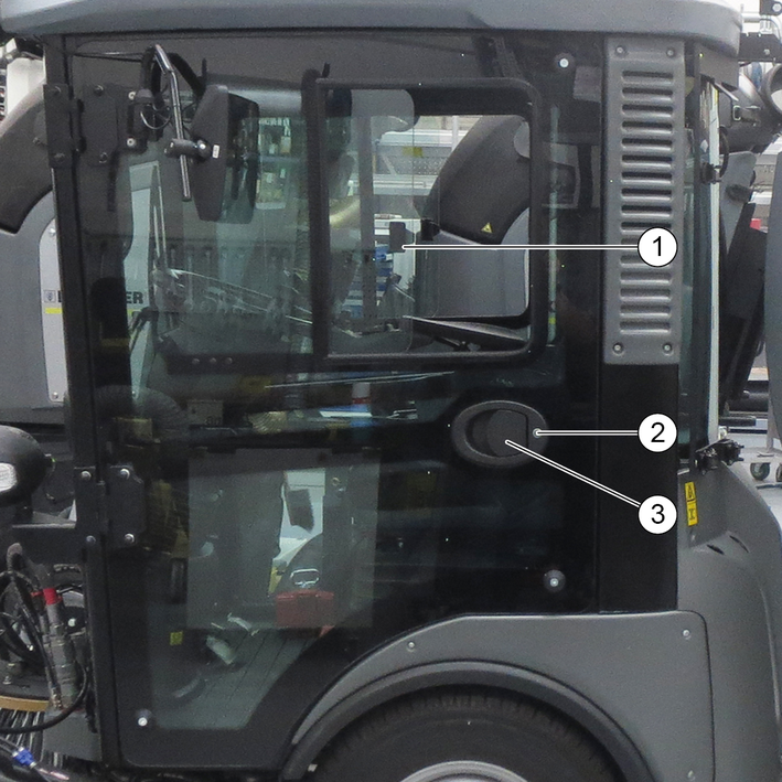
The driver's door is located at the left side in the travel direction, the emergency exit is located at the right side.
The door opener and door handles can be used as a aid for entering and exiting the cab.
Lock both doors with the ignition key after parking the vehicle.
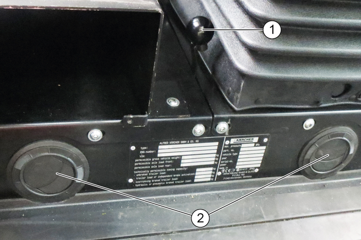
A lockable storage compartment is located under the passenger seat. This can be used for storing documents, operating instructions, small parts or the towing eye.
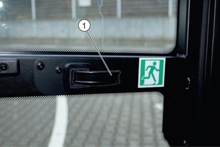
The emergency exit is located at the left side in the travel direction. Open the emergency exit by pulling the door handle.
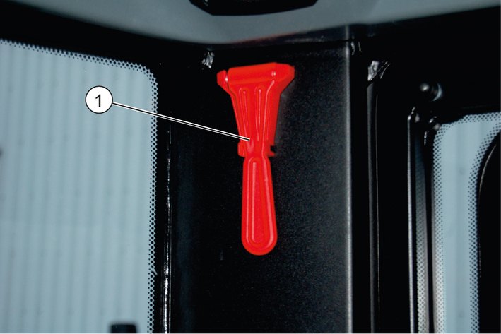
The emergency hammer is located at the upper left, behind the passenger seat. In case of emergency, destroy the windscreen with the emergency hammer.
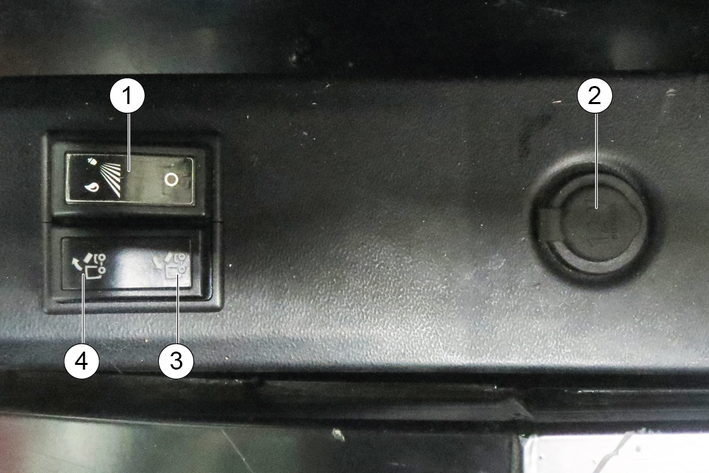
The control panel is located on the left arm rest of the driver's seat. The arm rest can be individually adjusted to suit the driver, see chapter Setting the driver's seat.
For left-hand drive vehicles (optional), e.g. for the UK, the control panel is located on the right arm rest of the driver's seat.
The indicators in the switches light when the switches are switched on.
Raise front power lift and front PTO off (back)
Lower front power lift and front PTO on (forwards)
Operate AUX 1 (right/left)
Switch on front power lift floating position (forwards)
Switch off front power lift floating position (back)
Operate AUX 2 (forwards/back)
Operate AUX 3 (left)
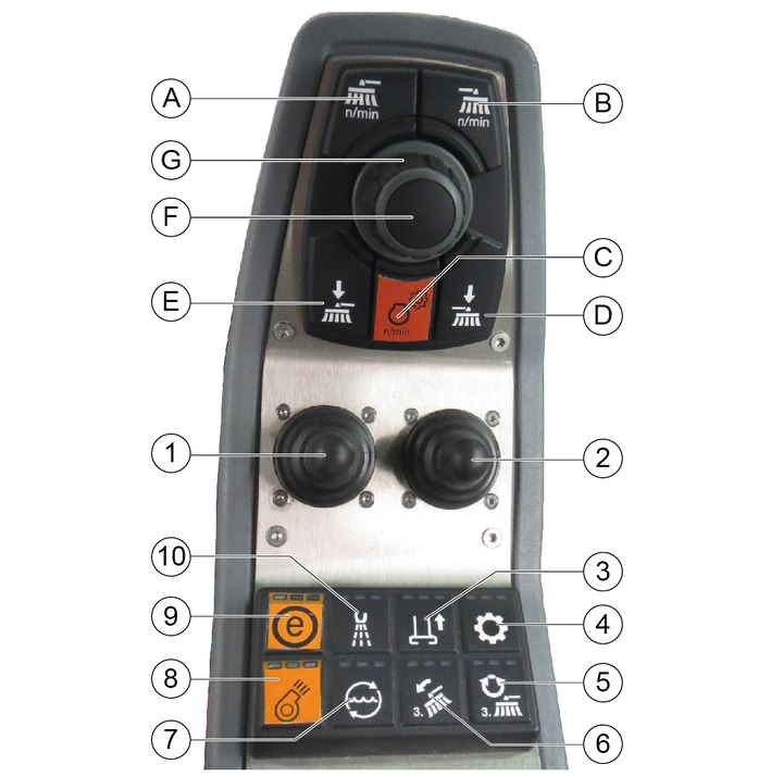
(A) | Front PTO 40 l/min, 80 l/min |
(B) | Rear PTO 40 l/min |
(C) | Button for setting the engine speed |
(D) | Not used |
(E) | Not used |
(F) | Press the button to save set values or programs and open submenus. |
(G) | Rotary knob for changing values and selecting programs. |
The indicators in the switches light when the switches are switched on.
The suction fan has an afterrun time of approx. 15 seconds after being switched off
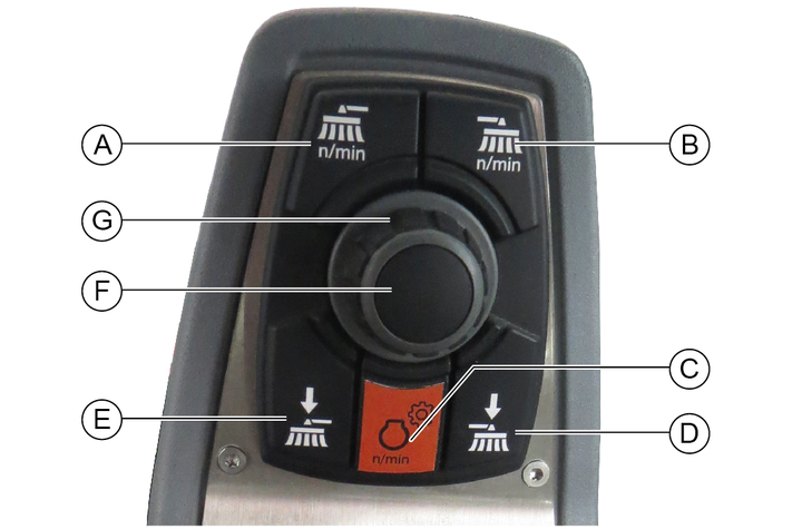
(A) | Left and right side brush speed button For individual extraction (option), left side brush speed button |
(B) | For individual extraction (option), right side brush speed button |
(C) | Engine speed Press to adjust the values NoteThe suction performance depends on the set engine speed.
|
(D) | For individual extraction (option), right side brush contact pressure button |
(E) | Left-hand and right-hand side brush contact pressure button For individual extraction (option), left side brush contact pressure button |
(F) | Save button Press to save adjusted values or programs |
(G) | Rotary knob Press to change the adjusted values |

The fresh air is sucked through a dust filter or fine dust filter at the side of the driver cabin.
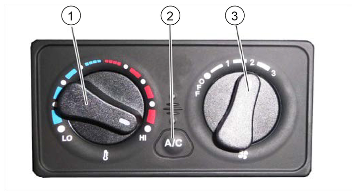
The circulation air function ensures that a fogged windscreen clears more quickly when the air-conditioner or air blower is switched on. The cab air can also be warmed more quickly. Also useful in the case of unpleasant outdoor odours.
Pull the air recirculation lever forwards.
Only use this function for a limited period, since air is not exchanged from the outside with this setting.
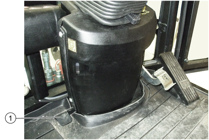
The switch for emptying the waste container is located next to the driver's seat.
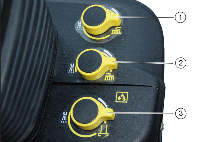
Switch on the water pump (control panel).
Turn the corresponding dosage knob.
Turning to the left increases the spray water volume. Turning to the right increases the spray water volume.

The indicator in the switch lights up when it is switched on.
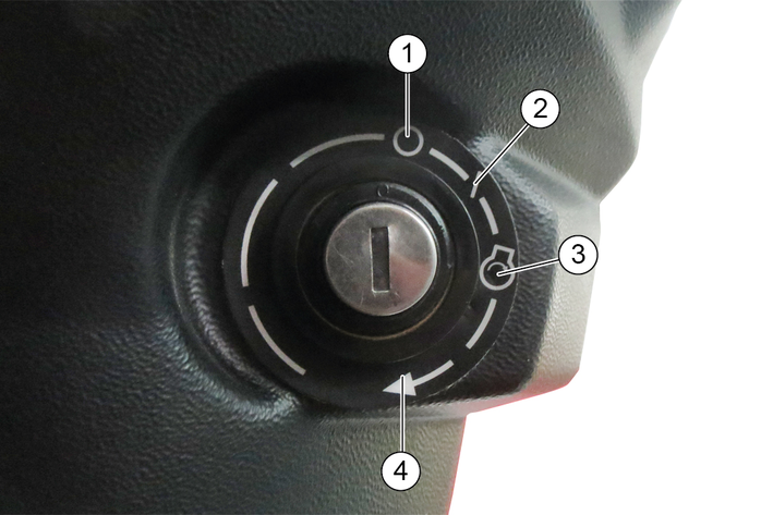
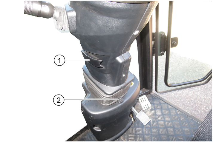
The ignition lock is located below the travel direction lever.
The following indicators are shown on the display after switching on the ignition.
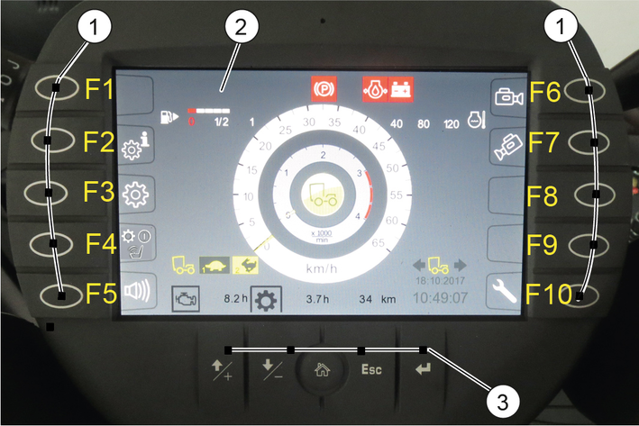
The display changes when the corresponding function button is pressed. Pressing again or pressing the "Home" button returns you to the previous display.
The settings button is used for changing the settings.
Function buttons | |
|---|---|
F1 | Information such as the vehicle operating instructions can be stored here In working mode: Switch in the high-pressure cleaner (Option) |
F2 | Display date and time |
F3 | Settings |
F4 | Bridging the seat contact switch, see chapter Operation with a bridged seat contact switch |
F5 | Reversing warning buzzer on/off |
F6 | Reversing camera on/off |
F7 | Suction mouth camera on/off |
F8 | Set Tempomat |
F9 | Resume Tempomat |
F10 | Service menu |
Setting buttons | ||
|---|---|---|
 | + button | Jumps one field up when making settings |
 | - button | Jumps one field down when making settings |
 | "Home" button | Navigates to the "Home" screen for the respective operating mode (Transport / Work) |
 | Esc button | Jumps one step back when making settings |
 | "Return" button | Completes a setting procedure |
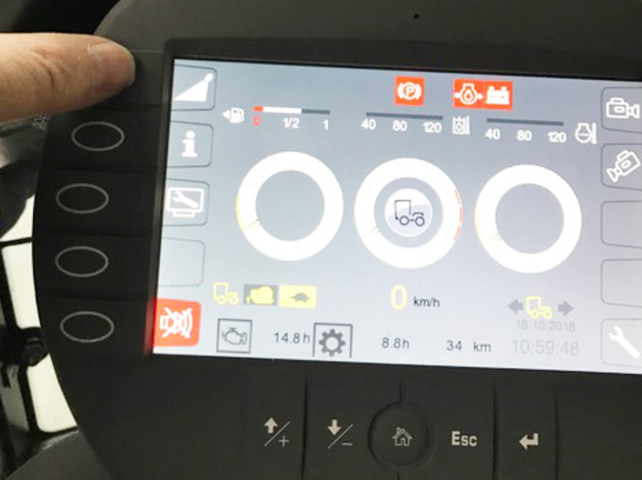
The following indicators are shown on the display in start/transport mode.
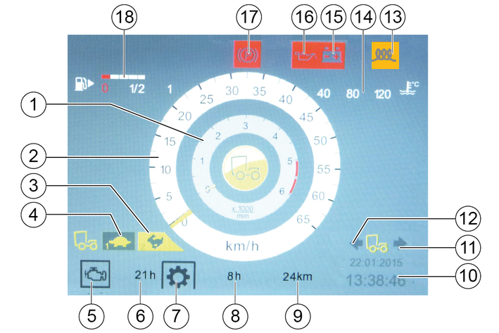
The following symbols and warning indicators can be shown on the display.
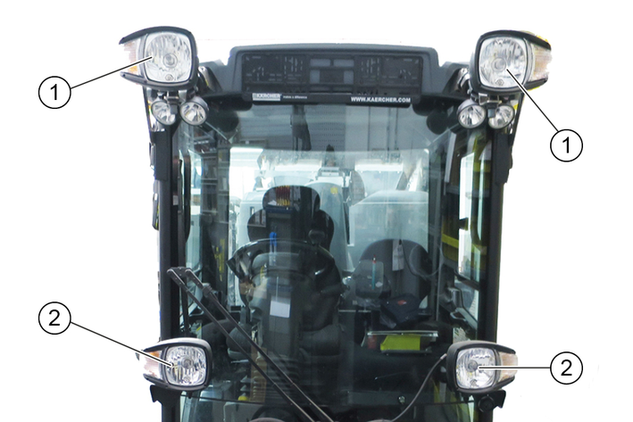
 | Parking light |
 | Driving light |
 | High beam |
 | Fog lamps |
 | Hydraulic oil filter malfunction |
 | Preheating active |
 | Battery charge status warning |
 | Malfunction |
 | Hydraulic oil level warning |
 | Fuel level warning |
 | Floating position 1 |
 | Floating position 2 |
 | Floating position 1 and 2 |
 | Driving direction indicator |
 | Perform the regeneration process |
 | Engine air filter malfunction |
 | Critical malfunction, switch off the engine |
 | Lower suction mouth |
 | Seat contact switch malfunction |
 | Engine coolant temperature warning |
 | Parking brake active |
 | Rear light indicator lamp flasher |
 | Engine oil pressure warning |
 | Hydraulic oil temperature too high warning |
 | Regeneration not possible |
 | High exhaust temperature |
 | Switch off the engine |
 | Engine malfunction |
 | Service required |
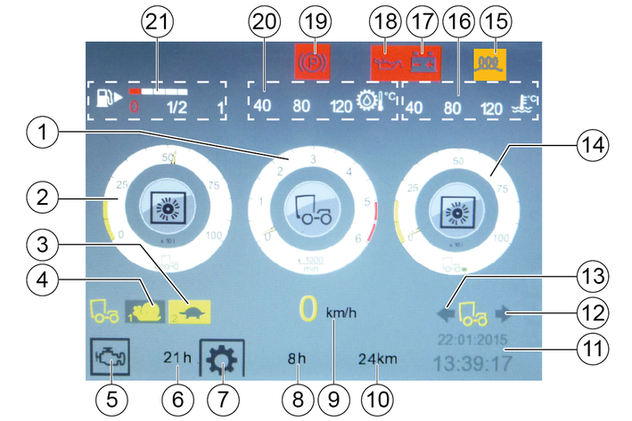
The following indicators are shown on the display when switching to Working mode (PTO).
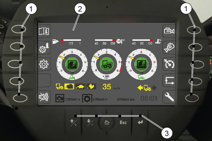
The function and settings buttons have already been described previously.
The following indicators are shown on the display when switching to Working mode (PTO).
The hydraulic system must be depressurised before disconnecting the hydraulic hoses from the hydraulic connections.
Unplug the signal plug for attachment device detection (front).
Switch on the ignition (do not start the engine).
Switch on the PTO work hydraulics (at the arm rest control panel).
Press the function key F 10 on the display.
Press function key F 6.
The rear hydraulic system is depressurised
Press function key F1.
The front hydraulic system is depressurised
Disconnect the hydraulic hoses.
Remove the attachment device.
Attachment is performed in reverse sequence.
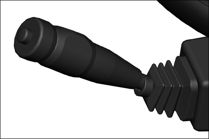
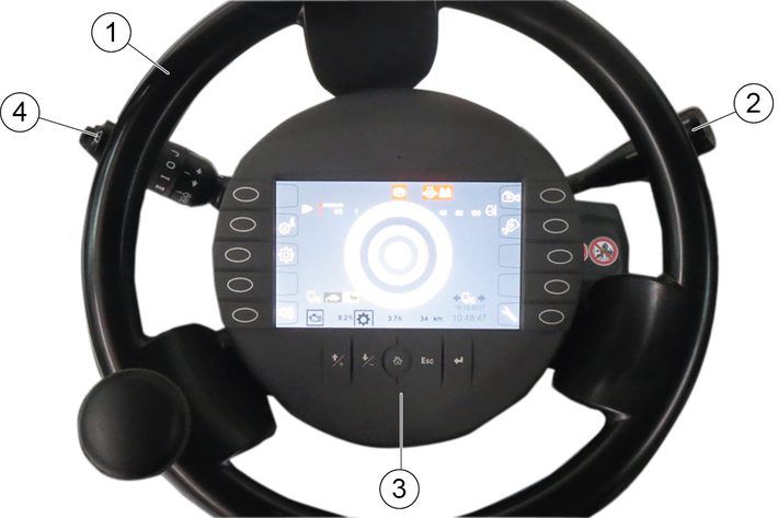
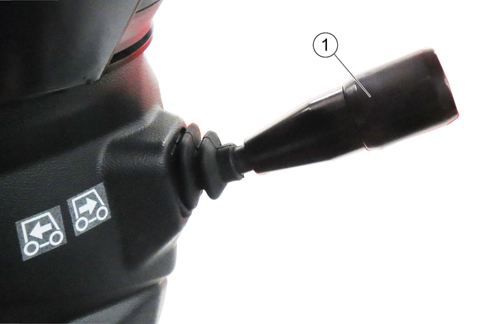
Horns: Press the button on the end
Flash to the right: Lever forwards
Flash to the left: Lever backwards
High beam: Press the lever down with the driving light switched on
Flasher: Pull lever and release
Turn the ring: Turn on the windscreen wiper
Turn forward - interval
Turn backwards - 1. Continuous wipe level, keep turning for 2nd level
Press the ring: Wiping with washer water
Select the travel direction using the travel direction selector switch.
The following functions can be selected using the travel direction selector switch, the selected programs are shown on the display.
Neutral position
The travel direction selector switch is in the middle
Forwards direction of travel
Press the travel direction selector switch upwards and forwards
Travel direction backwards
Press the travel direction selector switch upwards and pull backwards
Switchover between the fast (Hare) and slow (Tortoise) operating programs
Press the travel direction selector switch to the end position (travel direction switch must first be in the neutral position).
Other than in a normal motorcar, releasing the accelerator pedal abruptly reduces the speed.
The braking force applied when you release the accelerator pedal is weaker in higher gears and stronger in lower gears.
The braking force applied when you release the accelerator pedal in transport mode is significantly weaker than in working mode.
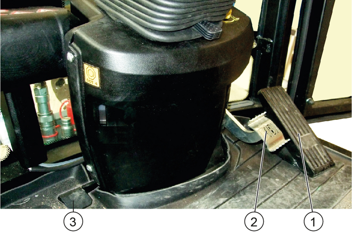
Pressing the accelerator pedal increases the engine speed.
The accelerator pedal is sprung. Releasing the accelerator pedal reduces the engine speed.
The hydrostatic drive brakes or stops the vehicle when the accelerator pedal is released.
The brake pedal activates the braking system for the front wheels.
Parking brake for securing the parked vehicle.
If the "Parking brake active" warning light in the display lights up then the parking brake is engaged.
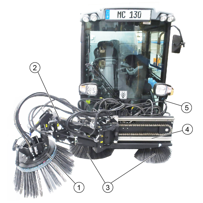
The structure of the vacuum sweeper consists of a waste container, sweeping mechanism and suction mouth.
Only accessories, spare parts and upgrade kits that are approved by the manufacturer may be used. To avoid risks, all repairs and installation of spare parts may only be carried out by the authorised customer service personnel. For information about accessories and spare parts, please visit www.kaercher.com.
The following accessories and options can be purchased additionally and attached to the device:
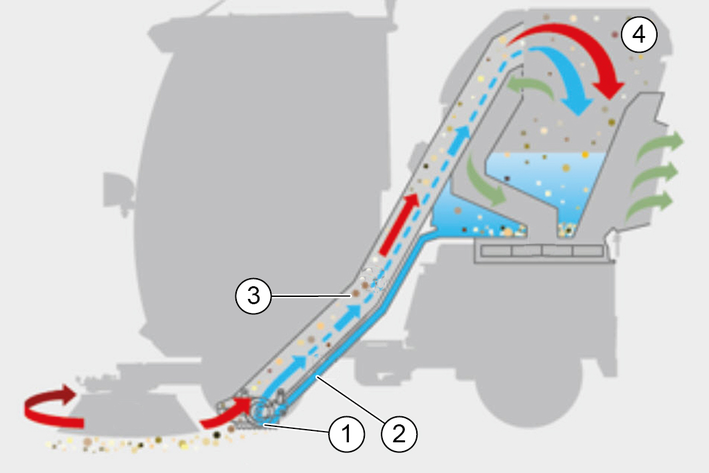
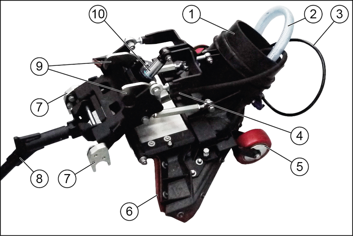
In recycling mode, the suction hose is continuously cleaned by water from the waste container.
The water is filtered by a pipe filter in the waste container and then channelled through the recycling water hose to the suction mouth via a valve.
This recycling water is immediate sucked in again at the suction mouth and then channelled back to the waste container through the suction hose.
The suction hose is continuously cleaned.
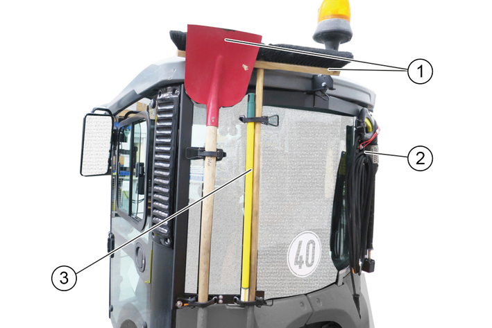
When retrofitted, the brackets must be installed and also the side panel cutouts for holding the brush and shovel handles.
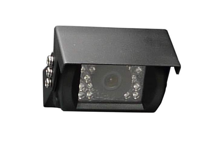
The suction mouth camera is fastened at the sweeper system suction mouth.
The reversing camera is located at the rear of the vehicle.
The reversing camera is no substitute for an awareness of the surroundings
Always pay attention to the surroundings when reversing.
Ensure no persons, animals or objects are located in the manoeuvring range.
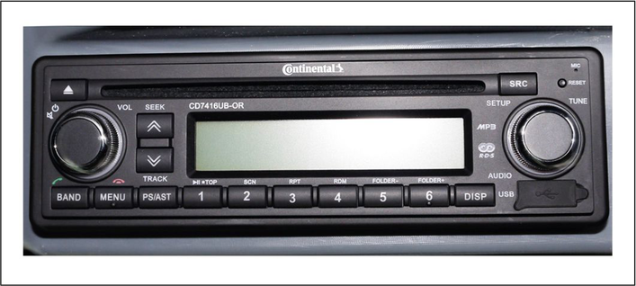
The optionally available radio is locate in the ceiling console.
See the manufacturer's operating instructions for operating the radio.
The seat contact switch can be bridged to allow using the work hydraulic system (PTO) when the driver's seat is not occupied.
This allows e.g. the suction hose or high-pressure cleaner to be used when nobody is sitting on the driver's seat.
This function is only possible in working mode, see chapter Bridging the seat contact switch.
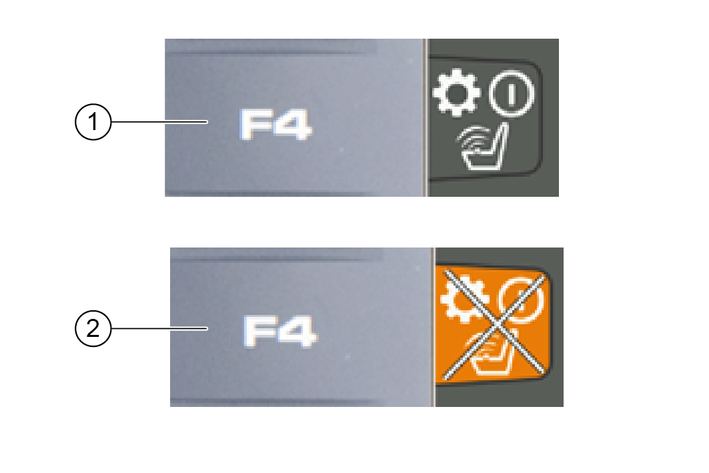
Apply the parking brake.
Press function key F4.
The "Seat contact switch overridden" warning symbol appears on the display.
Press function key F4 again to switch off the function.
The seat contact switch is now bridged and the PTO remains active.
Read the operating instructions for attachments!
When using attachments or pulled devices and trailers prior to initial startup, read the corresponding operating instructions and follow them.
Pay attention to permissible loads, see chapter Technical data.
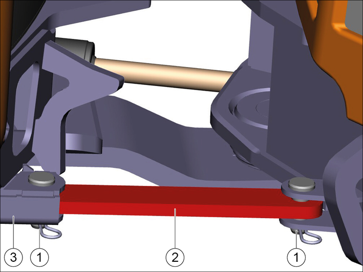
Pull out the locking pin.
Pull out both bolts.
Slide the transport lock into the storage.
Insert the pins.
Secure the pins with locking pins.
Put the main switch into the "battery connected" position.
Risk of accident and injury due to faulty vehicle
Do not start up the vehicle if one point from the safety check is not fulfilled but rather repair the vehicle.
Perform the recommended safety checks each time before using the vehicle.
Check the following points before each startup:
Release the transport lock, see chapter Release the transport lock at the articulated joint
Check the cleanliness of the hydraulic connections
Check the hydraulic lines for leaks
Check the hydraulic oil level, see chapter Checking the hydraulic oil level and topping up the hydraulic oil
Check the engine oil level, see chapter Checking the engine oil level
Check the coolant level, see chapter Checking the coolant level and topping up the coolant
Check the coolant for sufficient antifreeze if a danger of frost exists
Check the electrical cables for damage
Check that all nuts and bolts are securely seated
Check the vehicle, engine and radiator grille for damage
Check the cleanliness of the engine air filter
Check the cleanliness of the cab dust filter
Check the fluid level in the windscreen washer reservoir, see chapter Filling the wiping water container
Type pressures and tyre wear
In the vehicle
Ease of movement of the accelerator pedal
Are the working hydraulics (PTO) switched off?
With the ignition switched on: Do the charge indicator and oil pressure warning lights light up?
Start the engine and check the following:
Do the charge indicator and oil pressure warning lights go out?
Are the temperature indicator and fuel level indicator functioning?
Are the lighting system, travel direction indicator and flasher system functioning correctly?
Perform this safety check in addition to the device carrier safety check.
Check the operational and traffic safety of the vehicle before driving.
Fastening of the waste container.
Check the hydraulic and electric connections to the device carrier.
Check the spray water connections to the sweeping system and suction mouth.
Check the recycling water connection to the suction mouth (option).
Check the spray water filling level at the fresh water tank.
Recycling water filling level in waste container (option).
Check the sweeping system and brushes for entangled cords and tape.
Check the connections at the sweeping system and suction mouth.
Check the fastening of the sweeping system and suction mouth.
Danger of accident
Only adjust the driver’s seat when the device is standing.
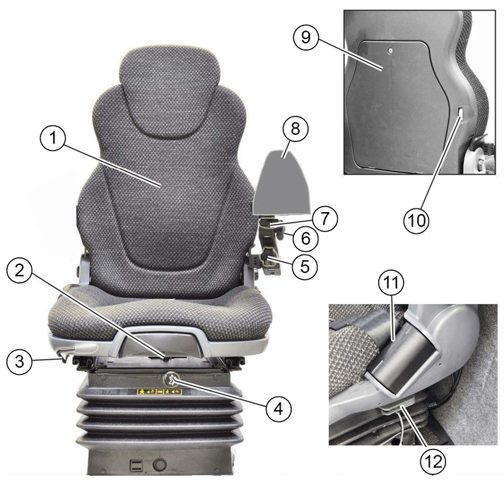
Adjust the inclination, height and position of the left arm rest for operating the control panel.
The driver's seat is automatically damped.
The passenger seat is horizontally adjustable, pull the lever upwards to adjust.
Danger of accident
Only adjust the position of the steering wheel when the device is standing.
Pull and hold the inclination adjustment lever and set the steering wheel to the desired inclination.
Push in the lever.
Release the height adjustment locking lever and set the steering wheel to the desired height.
Lock the locking lever.
Risk of explosion
Do not refuel in confined spaces.
Do not smoke and avoid open flames.
Ensure that no fuel gets on hot surfaces.
Switch off the ignition.
Open the tank cap.
Fill with fuel.
Only the fuel specified in the operating instructions may be used.
Wipe of any spilt fuel and close the tank cap.
Estimate the required amount of fuel in advance to avoid overflows.
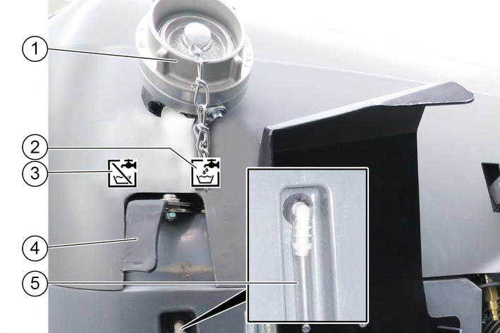
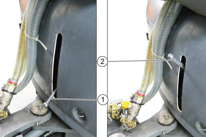
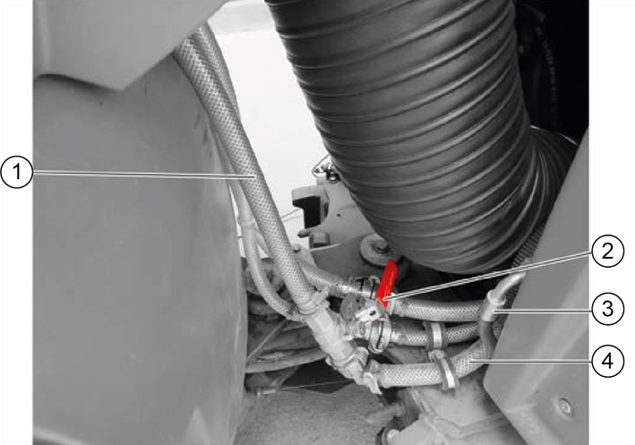
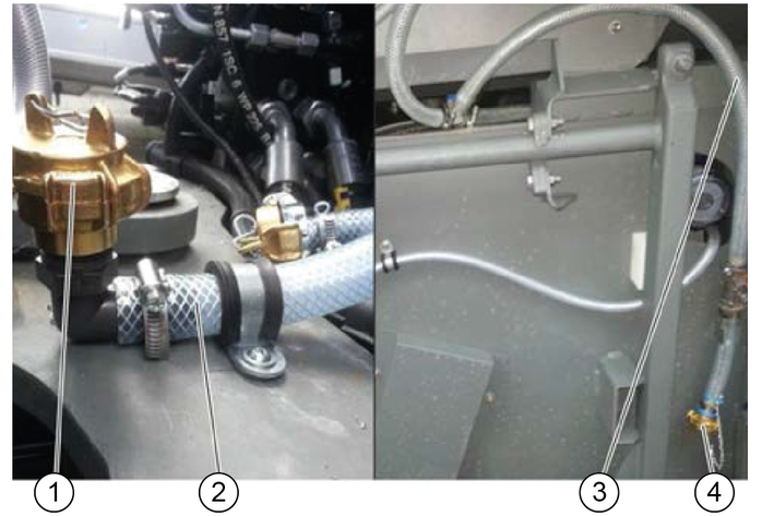
Open the cap on the filling nozzle.
Switch lever in the "Fill" position.
Fit a water supply hose onto the filling nozzle.
Fill the water reservoir.
To prevent back suction, the water hose must not be inserted into the water reservoir when filling.
Close off the water inlet.
Remove the water supply hose.
Close the cap on the filling nozzle.
Switch the switchover lever to the "Closed" position.
With a water circulation system (Recycling mode), water is directly filled into the waste container.
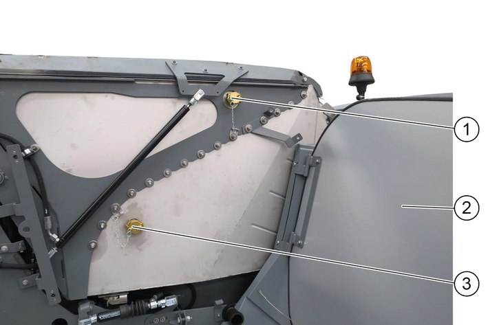
Unlock the right-hand panel and pivot it outwards.
Remove the lock from the water filling connection and water outlet.
Connect the water hose to the water filling connection
Fill the waste container with water (max. 100 litres) until water escapes from the open water drain.
Reattach both locks.
Close the panels.
Switch on recycling mode at the control panel.
Danger of crushing
Make sure that no persons are present in the vicinity of the articulated joint or vehicle during operation.
When using the vehicle for towing, make sure that no persons are located during operation between vehicle and trailer.
Risk of burns
Only use the vehicle if all panels are attached.
Risk of damage due to overheated hydraulic oil or overheated motor!
In case of excessive hydraulic oil temperature or an excessive coolant temperature, set the motor speed to idle mode (do not switch off the motor).
Perform the measures in the “Malfunctions” section
Risk of damage due to missing lubrication
If the warning light for the oil pressure lights up during operation, immediately move the vehicle out of the danger zone, switch off the motor immediately and rectify the fault.
Reduced stability due to attachments
Adjust the driving style.
Drive the first 100 hours of operation gently and avoid overloading.
Replace the engine oil, engine oil filter and hydraulic oil filter after 50 operating hours (authorised Customer Service department only).
The parking brake requires hydraulic pressure to release. The brakes are automatically actuated when the engine is switched off.
The parking brake is also applied when the engine is running and the travel direction lever is in the NEUTRAL position.
The "Parking brake applied" warning light in the multifunction display lights up when the parking brake is applied.
Adjust the ventilation, heating and air-conditioner (option) using the 3 controllers.
Adjust the volume and direction of the airflow at the ventilation nozzles.
The main switch must be switched on.
Sit down on the driver seat and fasten the seat belt.
Insert the ignition key into the ignition lock.
Set the travel direction lever into central position (neutral position).
Turn on the ignition.
Warning lights for charge control and motor oil pressure must be on.
Start the motor.
Warning lights for charge control and motor oil pressure must go out; if not, switch off the motor and rectify the error.
At ambient temperatures below 0 °C: Warm up the vehicle at a low motor speed until the “Hydraulic oil temperature too low” warning light goes out.
Press the travel direction selector switch towards the steering wheel and in the desired travel direction.
The travel direction is shown in the display.
Bring the travel direction selector switch into the middle position (neutral position).
The engine idles.
Press the travel direction selector switch to the end position.
Select the transport speed (between tortoise 20 km/h and hare 40 km/h).
The symbols are shown in the display.
Regulate the travel speed using the accelerator pedal.
Operating error
The vehicle must be at a standstill and the travel direction selector switch in the neutral position before changing the travel speed.
If the travel direction selector switch is in the forwards or reverse position when changing speed, the tortoise/hare symbol on the display will change but the travel speed will not switch over.
Risk of accident
Do not drive while the waste container is raised.
Risk of accident
Do not let go of the accelerator pedal abruptly during driving. The vehicle will be braked when the accelerator pedal is released. The vehicle will be decelerated to a lesser extent when the accelerator pedal is released in transport mode rather than in operating mode.
Risk of damage
Make sure that the vehicle does not become stuck when driving over obstacles.
Drive over obstacles up to 150 mm slowly and carefully at an angle of 45°.
Obstacles above 150 mm may only be driven over using a suitable ramp.
Risk of accident
When driving on public roads for transport purposes (and not when cleaning of public roads), switch off the PTO and close the lowering choke for the front power lift.
Switch off PTO.
Carefully depress the accelerator pedal.
Control the travel direction using the steering wheel.
Release the accelerator pedal.
The vehicle brakes automatically and comes to a standstill.
For a stronger braking effect or in case of an emergency, actuate the brake pedal.
The Tempomat is only active in Working mode.
Activating Tempomat
Select the desired working speed using the accelerator.
Press function key F 8.
Tempomat is activated.
Deactivating Tempomat
Press the brake pedal or function key F 8.
Function key F 9 (Resume Tempomat) activates the previously set speed.
Stop the vehicle.
Bring the travel direction lever into the neutral position (middle position).
In this position, the parking brake is automatically actuated; the vehicle does not move.
Lowe the front power lift.
If a sweeper is used:
Raise the side brushes.
Switching off the "eco" function
or
Switch off the water pump.
Wait 20 seconds.
Switch off the suction fan.
Raise the suction mouth.
Switch off the PTO.
All sweeping functions are deactivated.
Allow the engine to run in idle mode for 1 to 2 minutes.
Switch off the ignition and remove the ignition key.
Wait for 30 seconds to allow the engine control unit storage process to complete.
Turn the main switch to position 0.
Press the pedal briefly: Full brush contact pressure and increased brush speed for heavy soiling.
Hold the pedal pressed: Suction mouth remains lowered when reversing, vacuumed substances are also taken up when reversing.
(A) | Button for setting the side brush speed For individual extraction (option), left side brush speed button |
(B) | Button for setting the side brush speed For individual extraction (option), right side brush speed button |
(C) | Button for setting the engine speed NoteThe suction power depends on the set engine speed.
|
(D) | Left and ride brush contact pressure button For individual extraction (option), right side brush contact pressure button |
(E) | Left and ride brush contact pressure button For individual extraction (option), left side brush contact pressure button |
(F) | Press the Save button to save set values or programs |
(G) | Rotary knob for changing values and selecting programs |
Switch on the PTO.
Press the Side brush speed button.
The settings appear on the display.
Use the rotary knob to select the desired side brush speed.
Press the Save button.
The side brush speed has now been saved.
Press the Engine speed button.
The settings appear on the display.
Use the rotary knob to select the desired engine speed.
Press the Save button.
The engine speed has now been saved.
Press the Side brush contact pressure button.
The settings appear on the display.
Use the rotary knob to select the desired contact pressure.
Press the Save button.
The contact pressure is saved.
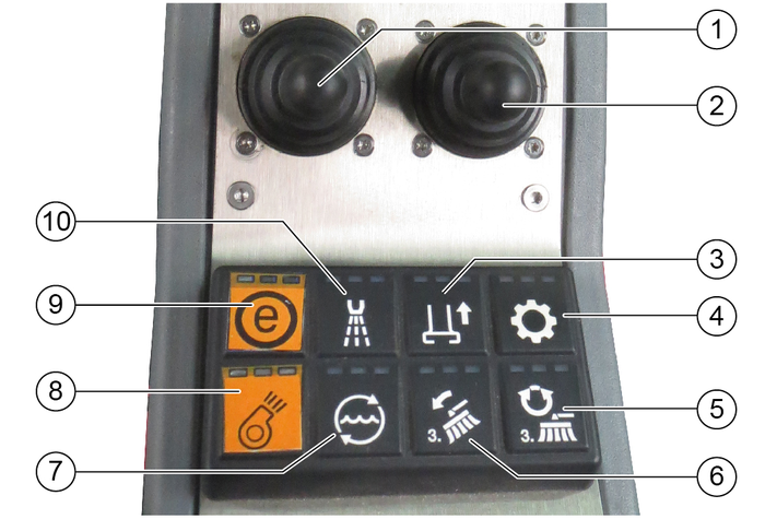
Operation with the right-hand joystick
The suction fan has an afterrun time of approx. 15 seconds after being switched off
The indicators in the switches light when the switches are switched on.
Start the engine, see chapter Start motor.
Switch on the hydraulic system.
Set the desired engine speed.
Switch on lower suction mouth.
Set the side brush speed.
Switch on the suction fan.
Move the left-hand joystick forwards.
The right and left brush arms are lowered and the brushes are switched on
Adjust the sweeping width.
Move the right-hand joystick forwards.
The right side brush lowers and is switched on.
Adjust the sweeping width (optional).
When brushing dry, dusty waste:
Switch on the water pump.
Optional: Switch on the water circulation function if necessary.
Risk of tilting
Only empty the waste container on a firm even subsurface.
Maintain the safety distance while emptying on dumps or ramps.
Danger due to rolling away
Set the travel direction lever to neutral for emptying.
Apply parking brake.
Danger of injury
Switch off the suction fan before emptying the waste container.
Risk of injury
During the emptying process, persons and animals must not abide within the swivelling range of the waste container.
Crush hazard
Never reach into the rod assembly for the emptying mechanism.
Stop the vehicle.
Apply the parking brake.
Bring the travel direction lever into the neutral position (middle position).
Set the switch lever to the "Waste container" position.
Switch on the PTO.
Lift the right side brush and switch it off by moving the left joystick to the right and then pushing it back.
Lift the right side brush by moving the right joystick to the left and then pushing it back.
Switch off the water pump.
Wait 20 seconds.
Switch off the suction fan.
Actuate the toggle switch.
Empty the waste container.
Note
Always raise the waste container fully to the end position.
The DPF collects soot particles that are burned off by increasing the emission temperature when the filter is clogged (regeneration).
The regeneration process runs either automatically during working mode or driving mode but can also be started manually if required.
The higher the speed when driving, or the greater the load, the less frequent the need for manual regeneration.
In this mode the engine control unit controls the regeneration independently. A symbol is displayed in the upper symbol bar of the display when the regeneration process is being performed. The tool key in the service menu is used for switching between Automatic and Manual regeneration.
With Manual regeneration, the driver decides when the Diesel particle filter (DPF) regenerations process is performed. There are 5 stages for this.
Manual regeneration - stage 1Stage 1 is triggered when the DPF has collected the maximum quantity of fine dust. A corresponding warning is emitted. If the driver has activated Automatic regeneration then this is started.
A symbol is displayed in the upper symbol bar of the display.
Manual regeneration - stage 2A flashing symbol is displayed in the upper symbol bar of the display when Automatic generation has not been performed or the engine control unit cannot perform this.
Either automatic regeneration or "Parked regeneration" can be activated.
Manual regeneration - stage 3A warning symbol in the upper symbol bar of the display notifies the driver that regeneration should be started immediately. Automatic regeneration is disabled, only "Parked regeneration" is permitted.
The vehicle can only be moved at a limited speed.
Manual regeneration - stage 4This type of regeneration can only be performed by service personnel. Automatic regeneration and "Parked regeneration" are disabled. The vehicle can only be moved forward at a limited speed.
A warning symbol is visible on the display.
Manual regeneration - stage 5Regeneration is no longer possible. A corresponding warning should be displayed in large format. "Parked regeneration" and automatic regeneration are disabled.
The vehicle can only be moved forward at a limited speed.
"Parked regeneration" can only be performed when the following requirements are met:
Travel direction position: Neutral
Parking brake active
Engine control unit does not display any error codes
Accelerator not actuated
Manual regeneration can be activated when these requirements are met.
The parked regeneration process takes approx. 30 minutes.
The seat cannot be vacated!
Risk of burns
During the regeneration process, exhaust gases up to a temperature of 600°C may be omitted.
Do not start the regeneration process in combustible areas.
Only interrupt the regeneration process in the case of an emergency.
If the regeneration indicator on the display lights up during operation then a regeneration process must be started.
Regeneration can be performed automatically or manually.
Work can continue during Automatic regeneration.
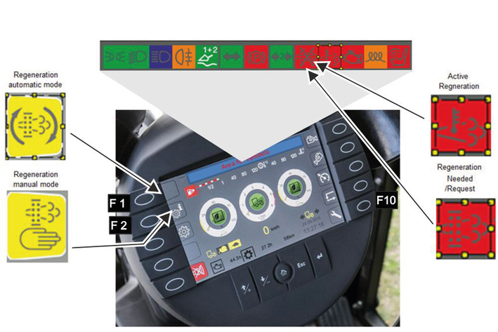
For manual cleaning ("Parked regeneration"), stop at suitable location within 15 minutes.
Regeneration duration is approx. 30 minutes.
Set the travel direction to the NEUTRAL position and do not press the accelerator pedal.
The driver's seat can be vacated during this period.
To start the regeneration process, first press function key F 10 (lower right key), then press F 1 for Automatic or F 2 for Manual cleaning.
The engine speed increases noticeably during both types of cleaning. When cleaning has finished the indicator lamp goes out and the engine speed decreases again.
The regeneration instructions above should suffice in most cases and more detailed descriptions are provided in the section "Faults with display".
Ensure there is enough antifreeze in the coolant.
During winter use, the sweeping system and suction mouth must be disassembled and placed into storage.
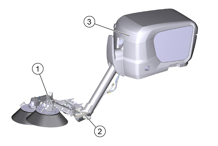
Use the high-pressure cleaner only for the following activities:
Cleaning with the high-pressure jet without detergent (e.g. façades, park seats, garden paths).
Only operate the high-pressure cleaner with the flat jet nozzle provided.
This high-pressure cleaner is intended and tested for the exclusive use with the sweeper vacuum MC 130.
When the water quantity is reduced via the pressure/quantity control on the trigger gun, the overflow valve opens and part of the water flows back to the suction side of the pump.
The safety valve opens when the permissible operating pressure is exceeded and the water flows back to the suction side of the pump.
Return flow of dirty water into the drinking water network
Health risk
Observe the regulations of your water supply company.
According to applicable regulations, the device must never be used with the drinking water network without a system separator. Use a system separator from KÄRCHER or a system separator as per EN 12729 Type BA. Water that has flowed through a system separator is classified as undrinkable. Always connect the system separator to the water supply and never directly to the water connection on the device.
Risk of injury from high-pressure jet
Do not direct the high-pressure jet at persons, animals, live electrical equipment or at the device itself.
Protect the device high-pressure cleaner frost.
Environmental pollution through oil
Clean engines only at locations having an appropriate oil separator.
Only nozzles of the sizes listed in the technical data may be used.
If you have not already done so:
Connect the high-pressure hose and spray lance.
Connect the water supply hose and open the stop cock of the water inlet.
The high-pressure cleaner may be operated only at an engine speed of 1600 rpm and only in work mode.
Check the water filling level and fill the water reservoir of the MC 130 if necessary.
Open the stop cock of the water inlet.
Put travel direction lever in the NEUTRAL position - centre position and start the motor.
Remove the trigger gun and high-pressure hose from storage.
Switch on the PTO work hydraulics.
Press F1 function key on the display and switch on the high-pressure cleaner.
Engine speed automatically increases to 1600 rpm.
A "high pressure" symbol appears in the display.
Switch on the high-pressure cleaner with the switch next to the driver's seat.
Unlock the trigger gun.
Pull the trigger on the trigger gun and commence cleaning.
For first use or when the water reservoir is empty, the high-pressure cleaner must be vented:
Operate the high-pressure cleaner without the nozzle until there is no more air in the system.
Close the trigger gun.
Switch off the high-pressure cleaner with the switch on the right of the driver's seat.
Switch off the work hydraulics.
Actuate the trigger gun until the device is depressurised.
Actuate the safety lever of the trigger gun to prevent the gun trigger from being unintentionally triggered.
Fasten and secure the trigger gun with spray lance and high-pressure hose in storage.
If the high-pressure cleaner is not needed, for example during winter operation (spreading salt and other work):
Blow out the system with compressed air - see chapter Frost protection.
Remove the high-pressure gun with spray lance and high-pressure hose from the device.
Take off the device cover (3 quick fasteners) and close the high-pressure output with the protective part intended for it.
Disconnect the water inlet at the GEKA connection.
Close the water inlet for the high-pressure pump.
Fix (store) the water supply hose of the water reservoir under the waste container.
Check all hydraulic hoses and connections for leaks.
Check the high-pressure hose for damage (danger of bursting).
Immediately replace a damaged high-pressure hose.
Check the device (pump) for leaks.
3 drops of water per minute are permissible and can leak out of the bottom of the appliance. Contact Customer Service in the case of more serious leaks.
To read the oil level or clean the water screen, remove the device cover (3 quick fasteners).
Read the oil level when the device is on a flat surface. The oil level must be in the middle of the sight glass.
Contact Customer Service immediately if the oil is milky (water in oil).
Clean the sieve in the water connection.
Depressurise the device.
Unscrew the cover with filter.
Clean the filter with clean water or compressed air.
Assemble in the reverse order.
Changing oil.
For oil quantity and type, see Technical data.
Have the oil changed by Customer Service.
Danger of frost
Incompletely emptied devices can be destroyed by frost.
Completely empty the device and accessories.
Protect the device from frost.
Store the device in a frost-protected place.
If frost-free storage is not possible:
Close off the water inlet.
Allow the device for run for a maximum of 1 minute until the pump and lines are empty.
Blow the high-pressure pump, supply hose, water filter and high-pressure hose out with compressed air.
Risk of injury due to inadvertently starting up device and also due to electric shock.
Switch off the device and remove the ignition key before performing any work.
Have electrical components checked and repaired by the authorised Customer Service.
In case of any malfunctions not mentioned in this chapter, contact the authorised Customer Service when in doubt or when you have been explicitly advised to do so.
Pump leaking
Up to 3 drops of water per minute are permissible.
Remedy:
In case of more serious leaks, have the device checked by Customer Service.
Pump knocking
Remedy:
Check the water supply line for leaks.
Vent the device, see section "Venting the device".
Contact Customer Service if necessary.
Switch on the work hydraulics and high-pressure switch.
Fill the water reservoir.
Clean the water inlet sieve, check the water supply.
Check/replace the high-pressure nozzle.
Hydraulic connection | ||
|---|---|---|
Supply from the hydraulic system of the MC 130 | ||
Connection output | kW | 4.5 |
Water connection | ||
Water supply from the water reservoir of the MC 130 | ||
Input temperature (max.) | °C | 60 |
Performance data | ||
Working pressure | MPa | 7-15 |
Nozzle size | 036 | |
Max. operating pressure | MPa | 19 |
Flow rate | l/min | 10 |
Recoil force of the trigger gun. (max.) | N | 30 |
Determined values in acc. with EN 60335-2-79 | ||
Sound pressure level LpA | dB(A) | 75 |
K uncertaintypA | dB(A) | 3 |
Sound power level LWA + K uncertaintyWA | dB(A) | 97 |
Hand-arm vibration value | m/s2 | 1.6 |
K uncertainty | m/s2 | 0.7 |
Operating materials | ||
Oil volume | l | 0.4 |
Oil type | SAE 15W-40 | |
Dimensions and weights | ||
Weight | kg | |
We hereby declare die technical documents according to EC Directive 2006/42/EC (+2009/127/EC) Annex VII Part B have been created for the incomplete machine described below and that this conforms to the following points of the directive:
Annex I Points 1.1, 1.2, 1.3, 1.4, 1.5, 1.6 and 1.7. I Point 1.1,
This declaration is invalidated by any changes made to the incomplete machine that are not approved by us.
Product: | Attachment kit |
High-pressure cleaner | |
Type: | 2.851-952.7 |
Harmonised standards used, based on: | |
EN 60335–2–79 | |
Authorities can request the relevant documentation for the incomplete machine from the documentation supervisor. Documents are provided via email.
Before commissioning or installation of the incomplete machine, it must be ensured that the complete machine into which the incomplete machine is installed conforms to the EC Machinery Directive 2006/42/EC (+2009/127/EC).
Please refer to the EC Declaration of Conformity for the machine for more information on this.
The signatories act on behalf of and with the authority of the company management.

Documentation supervisor:
S. Reiser
Alfred Kärcher SE & Co. KG
Alfred-Kärcher-Str. 28 - 40
71364 Winnenden (Germany)
Ph.: +49 7195 14-0
Fax: +49 7195 14-2212
Winnenden, 2017/07/18
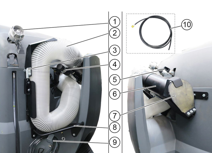
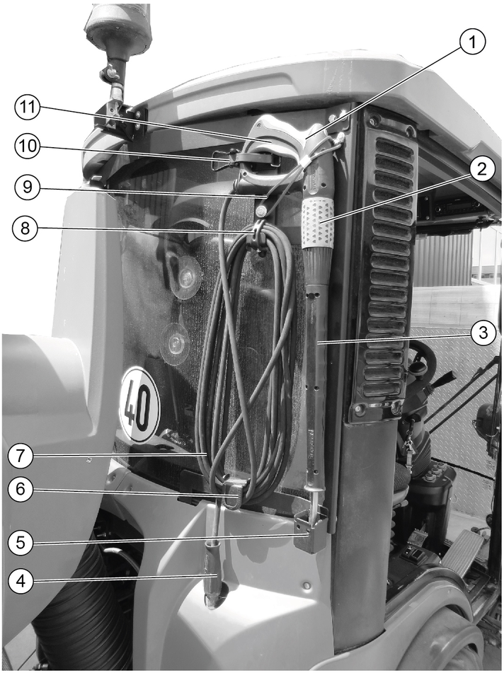
Remove the manual suction hose from the stowage compartment.
As necessary:
Connected the water hose provided and open the stop cock lever on the handle.
Close the dosing knobs in the cabin to prevent the emission of spray water for the suction mouth and sweeper jets, otherwise there will not be enough spray water for the manual suction hose.
Pull out the switch lever into the "Vacuum with suction hose" position.
Start the motor.
Switch on the PTO (at the arm rest control panel).
Switch on the blower.
As necessary: Switch on the water pump at the control panel.
Select the engine speed.
The suction performance depends on the engine speed selected.
1600 rpm - for light waste
2200 rpm - for normal waste
2500 rpm - for strong, heavy waste
Hold the suction pipe by the handle (adjustable) and begin vacuuming.
Set the engine speed to 2200 rpm for installing the manual suction hose.
When using the water hose: Switch off the water pump, disconnect the water hose and stop appropriately.
Insert the suction pipe with handle, press against the cover and fasten in position.
The vacuum pulls the suction pipe against the cover and the suction hose contracts. This is necessary to allow it to be stowed in the bracket.
Press the rest of the suction hose into the bracket and press the flap closed until the latch engages.
Switch off the blower.
Press in the switch lever into the "Work in sweeping mode" position.
Please read the attachment operating instructions before fitting an attachment.
Attachments are optional and can be fitted to the front power lift (see chapter Front power lift (option)) or to the front or rear mounting frames.
Danger due to change to vehicle's centre of gravity and to driving characteristics. When transporting fluids, sloshing motion may occur, which will then rock the vehicle.
In the case of modifications, particularly when converting from winter to summer use and in the case of changes to load conditions, the driver must be prepared for the change in driving characteristics.
Risk of crushing when attaching attachments
Do not reach between the front power lift and the attachment.
Risk of burns from hot hydraulic couplings
Wear protective gloves when disconnecting the hydraulic couplings.
Wear suitable protective clothing, safety gloves and gloves when installing and removing attachments. This also applies during usage and application.
Please contact your responsible dealer before fitting attachments that are not specifically intended for this vehicle. Your dealer will check if installation and use of these attachments is permitted on your vehicle. This is important for the safety of the driver and the vehicle and also for any warranty claims.
Attachments that endanger the safety or stability of the vehicle may not be used.
Risk of damage
Keep hydraulic connections clean.
Clean the plug and coupling with a lint-free cloth before use.
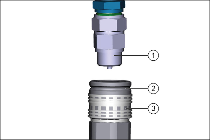
Pull the ring of the coupling sleeve downwards and hold.
Press the coupling connector of the attachment hydraulic hose into the coupling sleeve.
Release the coupling ring. Check that it is securely engaged.
To decouple, pull the ring downwards, hold it and pull out the hydraulic hose.
For permissible support load and trailer load, see chapter Technical data.
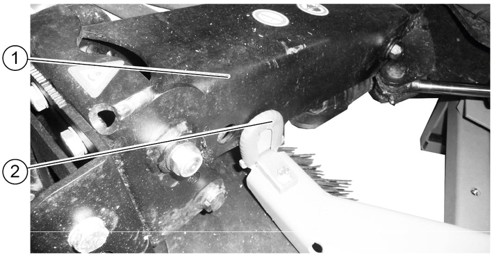
The locking mechanism secures the attachment devices (e.g. sweeper system, front power lift).
Danger of accident
Check the locking mechanism for correct adjustment with each attachment.
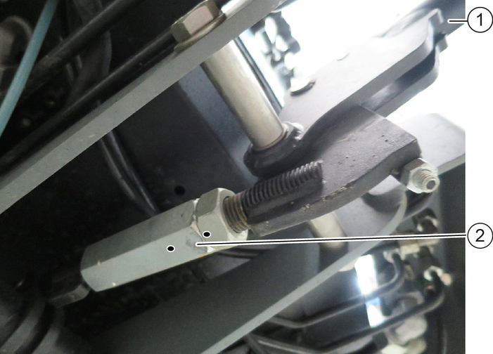
Press the locking lever downwards.
The lock is engaged beyond the dead point.
Adjust the lock via the clamping nut.
The front axle of the vehicle must always be loaded with at least 30% of the net weight of the vehicle, and the rear axle must always be loaded with at least 30% of the net weight of the vehicle.
Before purchasing the attachment, check that these requirements are met by weighing the vehicle-attachment combination.
The following data is required for determining the total weight, the axle loads, the tyre loading capacity and the required minimum ballast:
All weights in kg (weigh the vehicle if necessary)
All dimensions in meters (m)
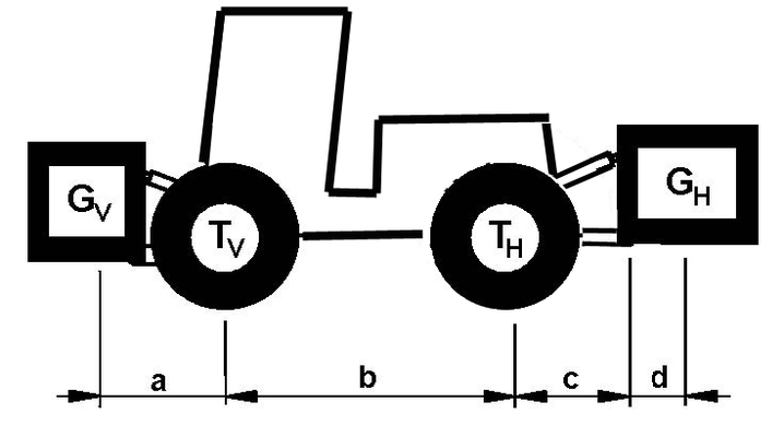
TL | (kg) | = | Net weight of the vehicle | * |
TV | (kg) | = | Front axle load of the empty vehicle | * |
TH | (kg) | = | Rear axle load of the empty vehicle | * |
GH | (kg) | = | Total weight rear attachment / rear ballast | ** |
GV | (kg) | = | Total weight of front attachment / front ballast | ** |
a | (m) | = | Distance between front attachment (front ballast) centre of gravity and middle of front axle, max. = 0.86 m | ** *** |
b | (m) | = | Wheelbase of the vehicle | * *** |
c | (m) | = | 0.56 | |
d | (m) | = | Distance between the centre of the equipment-side attachment point and the centre of gravity of the rear attachment / rear ballast | ** *** |
* See chapter "Technical data"
** See operating instructions of the attachment
*** Measure

Enter the result into the table.
See the manufacturer's specifications for the value "x" or use a value of x = 0.45 if no specifications are available.

Enter the result into the table.

If the necessary minimum front ballast weight (GV min) is not reached with the front attachment (GV) then the weight of the front attachment must be increased to the minimum front ballast weight.
Enter the actual calculated permissible front axle load and the permissible front axle load specified in the work machine operating instructions into the table.

If the necessary minimum rear ballast weight (GH min) is not reached with the rear attachment (GH), then the weight of the rear attachment must be increased to the minimum rear ballast weight.

Enter the result into the table.
Risk of crushing when lowering/raising the waste container
Maintain sufficient clearance to the waste container and the rollers on the parking supports.
Maintain sufficient clearance to hazard zone and stop raising/lowering immediately when a person enters the hazard zone.
Risk of injury and damage
The dirt receptacle and fresh water tank are empty.
Remove the waste container only on a level and smooth surface.
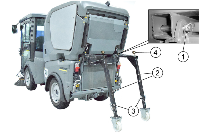
The waste container must be secured on the parking supports for installation.
Set the switchover valve to the attachment frame position.
Drive the rear of the vehicle carefully under the waste container.
Raise the attachment frame slowly until under the waste container.
Hook the waste container onto the attachment frame using the retaining hooks.
Continue raising the attachment frame until the load on the front parking supports is relieved.
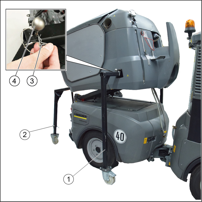
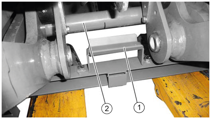
Lift the attachment frame only until the rollers of the front parking supports are approx. 20 mm in the air.
Pull out the front parking supports. For this, pull the retainer to unlock and then press the lever.
Completely lower the attachment frame together with the waste container.
Pull out the rear parking supports. For this, pull the retainer to unlock and then press the lever.
Push the retaining pin the of waste container in and secure with the locking pin.
Connect electrical and hydraulic connections.
Turn the steering wheel all the way to the right to provide better access to the connections on the articulated joint.
Connect the water recycling hose.
Connect the fresh water hose.
Connect the high-pressure cleaner hose (optional).
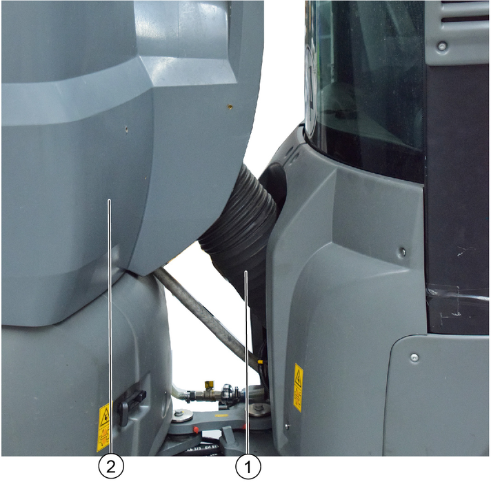
Install the suction hose between the waste container and suction mouth.
Risk of crushing when lowering/raising the waste container
Maintain sufficient clearance to the waste container and the rollers on the parking supports.
Maintain sufficient clearance to hazard zone and stop raising/lowering immediately when a person enters the hazard zone.
Risk of injury and damage
Empty the waste container and water reservoir before removing
Set the waste container down only on a level and smooth surface.
Turn the steering wheel all the way to the right to provide better access to the articulated joint.
Disconnect and remove the suction hose from the waste container.
Disconnect the hoses for water recycling, fresh water and the high-pressure cleaner (optional).
Steer the vehicle straight ahead.
Open the locking pin for the waste container from the retaining pin and remove it.
Pull out the retaining pin.
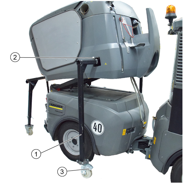
Adjust the rear parking supports to an appropriate height and secure in this position.
The corresponding height depends on the tyre type and the tyre pressure.
Push in the rear parking supports all the way to the end stops and secure in this position. To do this, press the safety lever down and push in the supports as far as they will go. Then secure the safety lever with the retaining clip.
Depressurise the hydraulic system, see chapter Depressurise the hydraulic system (pressure relief).
Disconnect the electrical and hydraulic connections from the waste container.
Set the switchover valve to the tilting attachment frame position. See chapter Waste container/attachment frame switchover.
Raise the attachment frame with waste container.
Push in the front parking supports as far as they will go and secure them. To do this, press the safety lever down and push in the supports as far as they will go. Then secure the safety lever with the retaining clip.
Lower the attachment frame.
Actuate the roller brakes on the front parking supports.
The waste container now stands free on the parking supports.
Drive the rear of the vehicle carefully out from under the waste container.
A changing carriage is required for attaching/removing the sweeper system.
Optional accessory, order no. 2.852-065.0.
Stop the vehicle on level, solid ground and secure it against rolling away.
Raise the side brushes and extend both side brushes outwards.
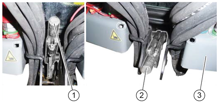
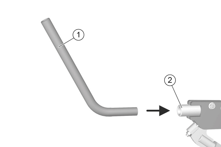
Rod
Locking lever
Unlock the sweeping system by inserting the rod and pulling the locking lever upwards.
The rod needed for this is clamped in a holder between the driver's seat and passenger seat.
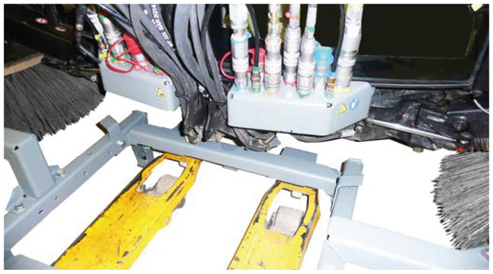
Use the lift truck to move the changing carriage centrally inwards as far as it will go.
Move the last distance (centring process) faster.
Risk of damage! Watch out for cables and hoses.
Raise the lift truck until the changing carriage makes contact with the sweeper system.
Retract both side brush arms.
Check the side brush arms for correct seating.
Depressurise the hydraulic system. See chapter Depressurise the hydraulic system (pressure relief).
Set the ignition to position 1 in working mode (do not start the engine).
The brushes lower and the hydraulic system depressurises.
Disconnect all connections and joints.
Remove the suction hose between the waste container and suction mouth.
Disconnect the (thick) water hose.
Move the sweeper system out using the lift truck.
Place the cables and hoses in the storage boxes.
Park the sweeper system in a safe place.
Extend the lift truck.
Stop the vehicle on level, solid ground and secure it against rolling away.
Attach the sweeper system to the vehicle in the reverse sequence.
Lock the sweeper system (lever down).
Check the locking, see chapter Checking adjusting the attachment locking mechanism.
Depressurise the hydraulic system. See chapter Depressurise the hydraulic system (pressure relief).
Connect the hydraulic hoses to the couplings.
Various different attachment devices can be attached to the front power lifter using a 3-point mounting.
A changing carriage is required for attaching/removing the front power lift.
Optional accessory, order no. 2.852-067.0.
Stop the vehicle on level, solid ground and secure it against rolling away.
Move the locking lever upwards.
Use the lift truck to position the front power lift centrally in front of the vehicle.
Insert the front power lift into the mounting frame on the vehicle, all the way to the end stop.
Move the locking lever downwards.
Check the locking, see chapter Checking adjusting the attachment locking mechanism.
Lower and retract the lift truck.
Depressurise the hydraulic system. See chapter Depressurise the hydraulic system (pressure relief).
Connect the hydraulic hoses to the couplings.
Raise the front power lift.
Use a lift truck to move the changing carriage under the front power lift.
Raise the lift truck.
Make sure that the frame of the front power lift is securely seated in the mounting of the removable frame.
Depressurise the front hydraulic system (pressure relief).
Release the hydraulic hoses.
Fasten the hydraulic hoses to the front power lift with cable ties.
Open the lock on both sides of the vehicle, see chapter “Opening/closing the lock”.
Use a lift truck to move the front power lift out of the vehicle mounting frame.
Set down the front power lift in a safe place.
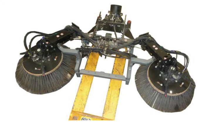
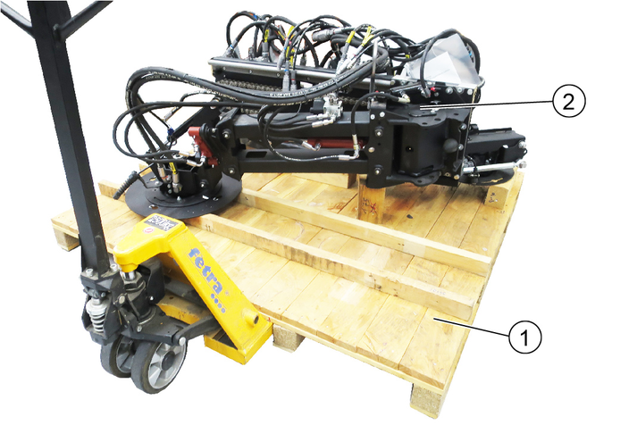
The pallet on which the sweeper system is delivered is also used as a mounting aid for attachment/removal.
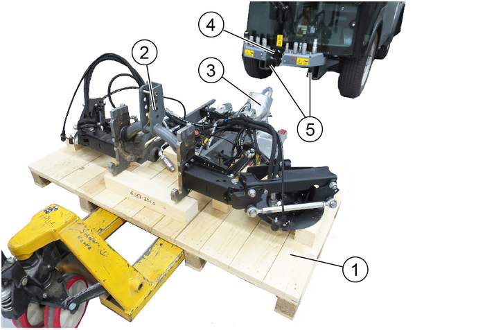
Move the lift truck under the pallet with the positioned sweeper system.
Pull the locking lever upwards.
Move the sweeper system into the holder on the vehicle and position it approximately 10 cm in front of the vehicle.
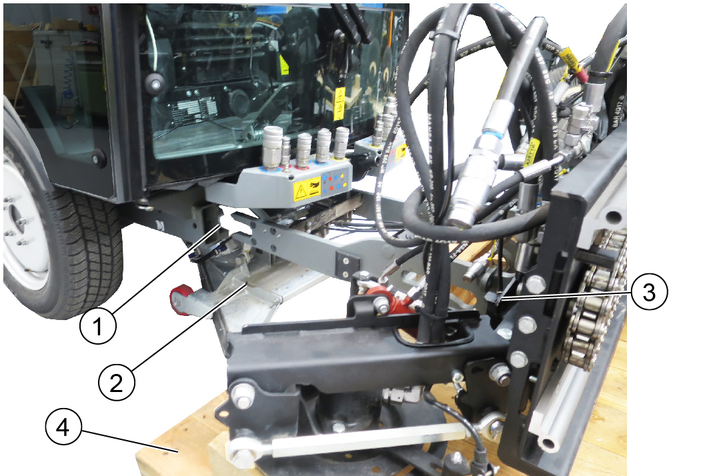
Connect the hydraulic hoses, paying attention to the colour coding.
The connection assignments are described in a later chapter
Connect the water hoses.
Insert the device detection connector at the vehicle.
Insert the sweeper system into the vehicle mounting bracket, all the way to the end stop.
Lock the sweeper system by pressing the locking lever down (using the curved rod).
The locking mechanism must be adjusted correctly via the adjusting nuts when the system is attached for the first time or transferred to another vehicle. When correctly adjusted, the locking mechanism must engage when pressed down beyond the dead point.
Attach the side brushes.
Operation of the 2-brush sweeper system is described in a later chapter.
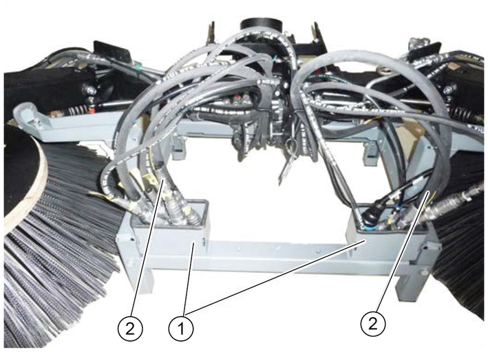
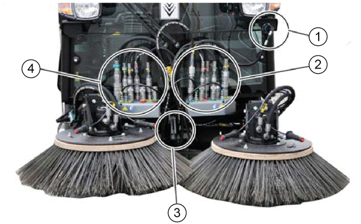
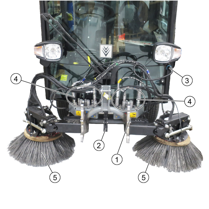
Plug in the hydraulic hoses according to the colour coding.
Plug in the water hoses at the left and right sides.
The indicators in the switches light when the switches are switched on.
Joystick forwards: Lower the brush arms simultaneously and switch on the side brushes
Joystick backwards: Raise the brush arms simultaneously and switch off the side brushes
Joystick to the left/right: Pivot the brush arms simultaneously
(A) | Sweeping brush speed selection, common for the left-hand and right-hand sides |
(B) | Button is not used |
(C) | Engine speed Press to adjust the values NoteThe suction power depends on the set engine speed.
|
(D) | Not used |
(E) | Left-hand and right-hand side brush contact pressure button |
(F) | Save button Press to save adjusted values or programs |
(G) | Rotary knob Press to change the adjusted values |
Switching over to the 2-brush sweeping system (pulled):
Switch on the ignition.
Press F10 on the vehicle display.
Use F5 to select a pulled sweeper system.
A green bar in the display indicates a reduction in the brush contact pressure.
A red bar indicates an increase in the brush contact pressure.
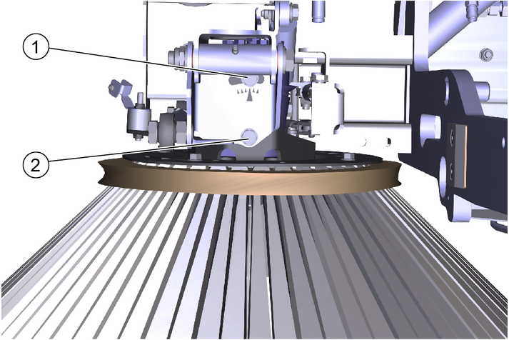
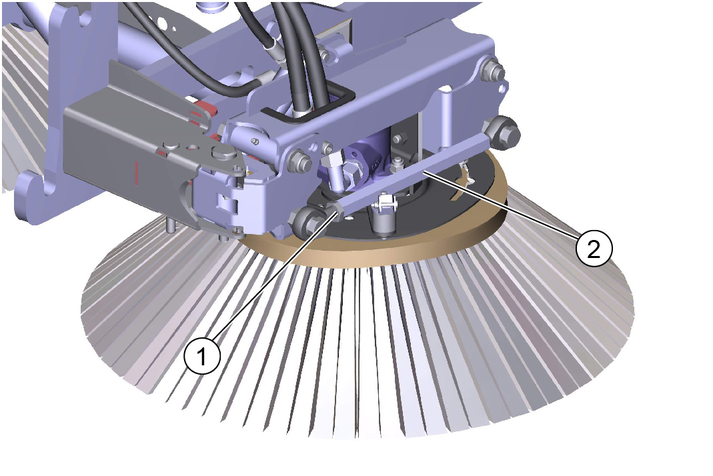
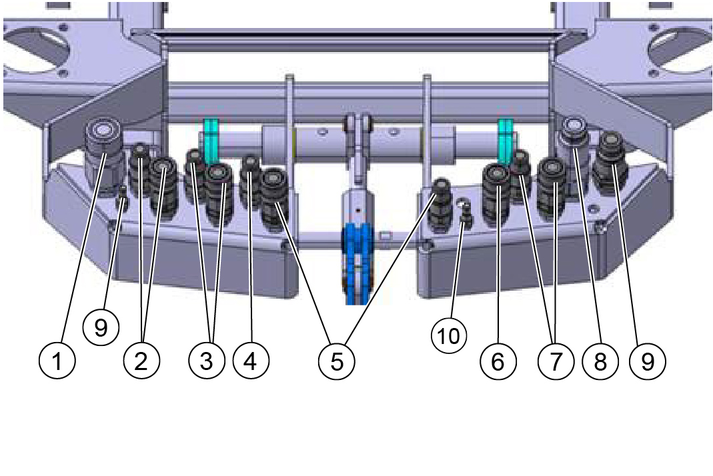
The existing lubrication points (grease nipples) are labelled.
Lubricate daily with multi-purpose grease.
Check the sweeping brushes for tangled cords and straps and remove as necessary.
Keep the hydraulic connections clean and check for leaks once a week.
Check the sweeping brushes for wear and damage and replace if necessary.
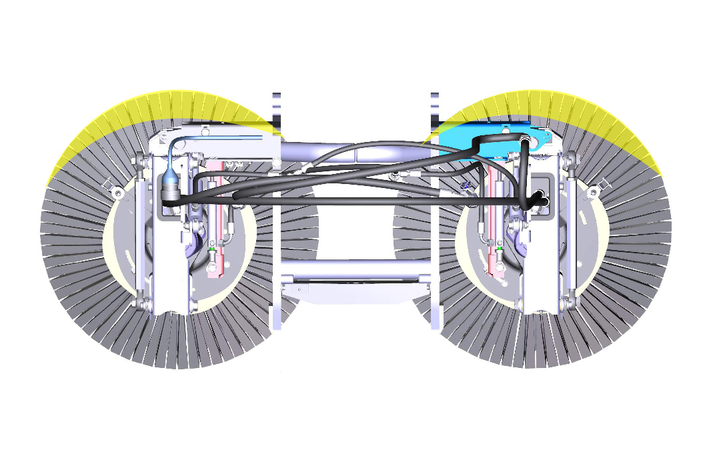
Adjust the sweeping area as shown in the illustration.
Right: 9 am- 2 pm
Right-hand side: 10 am- 3 pm
Adjusting the side inclination
Unscrew the screws.
Adjust the side inclination via the rotation point of screw 1.
Tighten the screws.
Adjusting the head inclination forwards
Unscrew the counternut.
Adjusting the head inclination via the hexagon.
Tighten the counternut.
Adjusting the brush contact pressure
The brush system has a hydraulic brush contact pressure relief system.
Risk of injury and damage
Note the weight of the device.
Risk of damage
Store the attachment kit in a protected, level and dry place. Ensure that the sweeping brushes are not loaded.
Store the sweeping system that has been removed from the vehicle on the changing carriage.
Ensure that the sweeping brushes are not loaded during attachment to the vehicle.
Dimensions and weights | 2-brush sweeping system (pulled) |
|---|---|
Length | 950 mm |
Width | 1250 mm |
Height | 750 mm |
Weight (transport weight) | 115 kg |
Remove the sweeper system in the reverse sequence to the attachment procedure. Set the sweeping system down on the pallet. Remove the sweeping brushes first.
Always first depressurise the system before disconnecting the hydraulic hoses, see the corresponding section in the vehicle operating instructions.
The pallet on which the sweeper system is delivered is also used as a mounting aid for attachment/removal.
Move the lift truck under the pallet with the positioned sweeper system.
Pull the locking lever upwards.
Position the sweeper system approximately 10 cm in front of the vehicle.
Connect the hydraulic hoses, paying attention to the colour coding.
The connection assignments are described in a later chapter
Connect the water hoses.
Plugging in the electrical socket plug connection on the vehicle.
Insert the sweeper system into the vehicle mounting bracket, all the way to the end stop.
Lock the sweeper system by pressing the locking lever down (using the curved rod).
The locking mechanism must be adjusted correctly via the adjusting nuts when the system is attached for the first time or transferred to another vehicle. When correctly adjusted, the locking mechanism must engage when pressed down beyond the dead point.
Attach the side brushes and front brush.
Operation of the sweeper system is described in a later chapter.
Plug in the hydraulic hoses according to the colour coding.
Plug in the water hoses at the left and right sides.
The indicators in the switches light when the switches are switched on.
Joystick forwards: Front brush lowers and switches on
Increase the contact pressure in the case of heavy soiling
Joystick backwards: Front brush raises and switches off
Joystick to the left/right: Front brush moves to the left/right
Joystick forwards: Lower the brush arms simultaneously and switch on the side brushes
Joystick backwards: Raise the brush arms simultaneously and switch off the side brushes
Joystick to the left/right: Pivot the brush arms simultaneously
(A) | Front brush rotary speed selection |
(B) | Sweeping brush rotary speed selection |
(C) | Engine speed Press to adjust the values NoteThe suction power depends on the set engine speed.
|
(D) | Sweeping brush load relief |
(E) | Front brush load relief/pressure |
(F) | Save button Press to save adjusted values or programs |
(G) | Rotary knob Press to change the adjusted values |
A green bar in the display indicates a reduction in the brush contact pressure.
A red bar indicates an increase in the brush contact pressure.
The front brush must be secured in the desired position when using the device as a weed brush.
Three positions are possible.
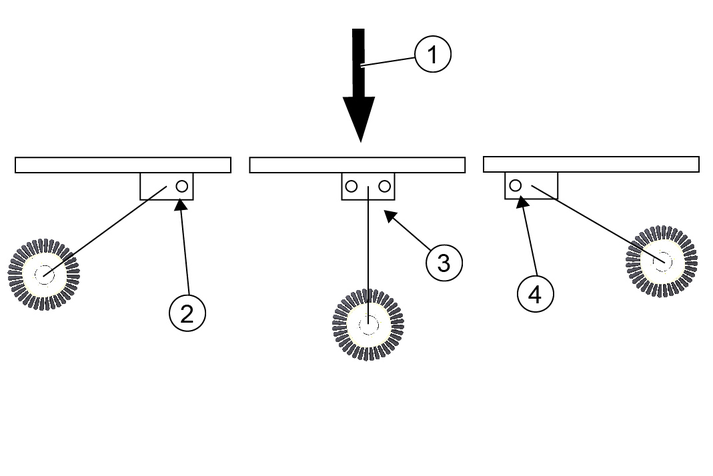
Secure the desired working position with bolts and spring pins. See chapter Transport lock.
Press the Change of rotation direction button when working in the Left position.
The front brush must be secured when driving on public roads (transport journeys).
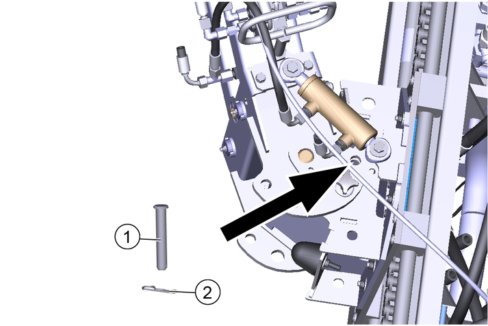
Move the front brush carriage all the way to the left.
Secure the front brush in the corresponding position using a pin and spring pin.
Further information can be found in the operating instructions for the vehicle.
Maintenance and care of the sweeping unit
Check the front brush and sweeping brush for tangled cords and straps and remove as necessary.
Keep the hydraulic connections clean and check for leaks once a week.
Check the front brush and sweeping brush for wear and tear and replace if necessary.
Maintenance and care of the bearings/linear unit
Malfunction or risk of damage
The bearing units are self-lubricating dry bearings and must never be lubricated with any lubricant.
Brake cleaners, lubricants or other cleaners can corrode and destroy the bearing foil. Check the bearing foil for wear and damage and replace if necessary.
The existing lubrication points (grease nipples) are labelled.
Lubricate daily with multi-purpose grease.
Clean the entire linear unit with water or brine. Cleaning with a high pressure cleaner is not a problem.
Maintenance and care of the chain
Notes on lubricating the chain
When lubricating the chain, make sure that no lubricant gets onto the rails of the linear unit. Should this happen due to carelessness, they must be cleaned and free of grease before initial startup.
Never use stains or acids to clean the chain.
Inspect the chain at least once a month. During the inspection, clean the chain, tension the chain drive and lubricate it.
The chains can be cleaned with rags or brushes. Stubborn dirt can be loosened with petroleum or benzine. Apply new, suitable corrosion protection immediately after using grease-dissolving media.
The chain drive may only be tensioned by Kärcher Service.
Regular lubrication extends the service life. Lubricate the chain with relubricant VP8 FoodPlus Spay from IWIS.
Note that the lubricant must get into the chain joint. This means that it has to get between the protective roller and the bushing, and also between the inner and outer plates to the pins and bushing
If you notice a lack of lubrication in the form of increased noise, stiff joints or fretting corrosion in the joints, we recommend the following procedure.
Clean the chain with a very low viscosity oil. This flushes fretting corrosion, old lubricant and other dirt from the joint. When the chain has been cleaned, lubricate it with a suitable lubricant as described above.
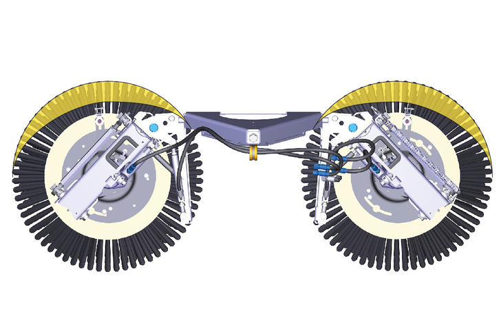
Adjust the sweeping area as shown in the illustration.
Right: 9 am- 2 pm
Right-hand side: 10 am- 3 pm
Adjusting the side inclination
Unscrew the screws.
Adjust the side inclination via the rotation point of screw 1.
Tighten the screws.
Adjusting the head inclination forwards
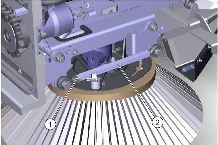
Unscrew the counternut.
Adjusting the head inclination via the hexagon.
Tighten the counternut.
Adjusting the brush contact pressure
The brush system has a hydraulic brush contact pressure adjustment system.
Risk of injury and damage
Note the weight of the device.
Risk of damage
Store the attachment kit in a protected, level and dry place. Ensure that the sweeping brushes are not loaded.
Store the sweeping system that has been removed from the vehicle on the changing carriage.
Ensure that the sweeping brushes are not loaded during attachment to the vehicle.
Dimensions and weights | 3-brush sweeper system |
|---|---|
Length | 1800 mm |
Width | 1250 mm |
Height | 850 mm |
Weight (transport weight) | 285 kg |
Remove the sweeper system in the reverse sequence to the attachment procedure. Set the sweeping system down on the pallet. Remove the sweeping brushes first.
Always first depressurise the system before disconnecting the hydraulic hoses, see the corresponding section in the vehicle operating instructions.
Risk of injury due to incorrect transport
Mind the weight of the vehicle.
Slowly and carefully drive the vehicle onto the transport vehicle.
Damage to vehicle
Do not load the vehicle with the crane.
Do not use a forklift.
Slowly drive the vehicle onto the transport vehicle.
If the vehicle is not ready for running, see Chapter Towing the vehicle.
Pull out the safety cotters.
Pull out both bolts.
Remove the transport lock out from storage.
Attach the transport lock.
Insert the bolts.
Lock the bolts with safety cotters.
Danger of accident
Secure the vehicle against slipping during transport.
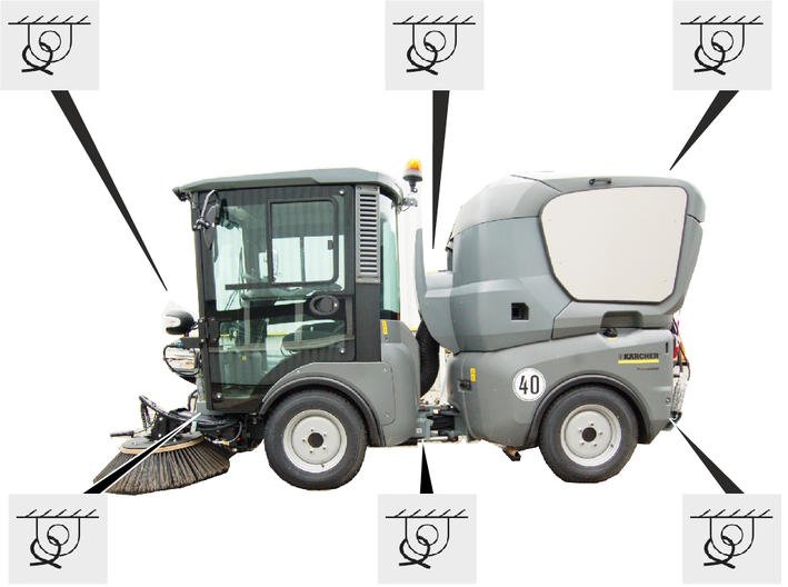
Park the vehicle.
Secure the vehicle with lashing straps on both sides at the illustrated lashing points.
If the vehicle with waste container is loaded in reverse for transport, the cover of the waste container must be additionally secured with a strap to prevent it from opening.
The towing eye with retaining pin and locking pin are located in a storage compartment under the passenger seat.
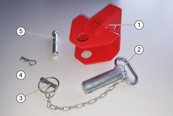
Open the storage compartment under the passenger seat and remove the towing eye.
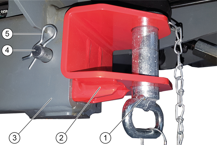
Attach the towing eye at the front of the vehicle chassis on the right-hand side.
Insert the retaining pin into the towing eye and secure with the locking pin.
The towing hook for MC 130 advanced is stored behind the passenger seat on a special holder along with the safety bolts and safety bracket.
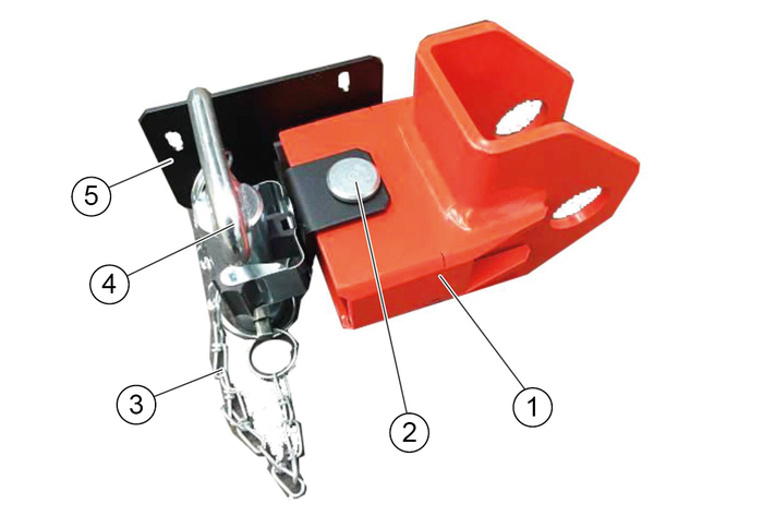
Remove the towing eye with locking pin and safety bracket from the holder.
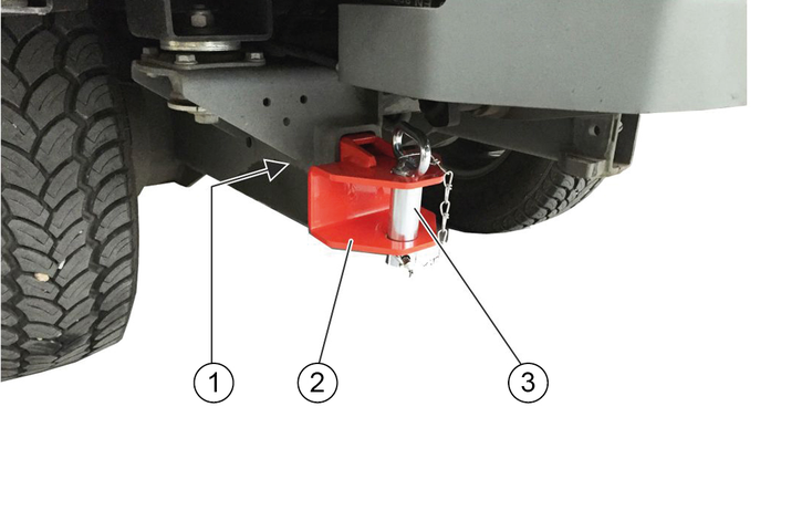
Attach the towing eye to the front of the vehicle frame.
Insert the retaining pin into the towing eye and secure with the locking pin.
Risk of damage due to incorrect towing
Only tow the vehicle away at walking speed.
Start up the towing vehicle slowly without jolting.
Fasten the towing rope or towing bar to the towing catch only.
Make sure the steering is working.
Release the parking brake spring actuator.
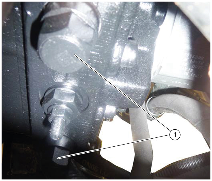
Unscrew the bypass valves 3 revolutions (width across flats 24 mm).
Attach a towing bar or towing rope to the towing eye.
Pull the vehicle slowly onto the transporting vehicle.
Close the parking brake spring actuator and bypass valves.
Crush hazard
When working under raised attachments, ensure these are always mechanically locked (shimming).
Before you clean and service the vehicle, or exchange parts or adjust them to a different function, switch off the motor and remove the ignition key.
Check if your radio is secured with a radio code before disconnecting the battery.
Disconnect the battery before working on the electrical system.
Repairs may only be carried out by authorised customer service centres or by qualified staff in this area who are familiar with all relevant safety instructions.
Any welding work on the vehicle or attachments is only permitted by authorised Kärcher Customer Service.
The service indicator lights up when the respective maintenance needs to be done.
The service indicator flashes on the display:
after 50 operating hours when the initial inspection needs to be performed.
Next service after 250 operating hours.
Then every 500 operating hours.
The service indicator must be reset by the Customer Service.
In order to preserve warranty claims, all servicing and maintenance work during the warranty period has to be performed by an authorised Kärcher Customer Service, in accordance with the inspection check list.
Daily before starting operation, see chapter Safety checks before startup.
Lubricate all bearings after washing the vehicle.
If necessary have the safety checks according to the applicable local regulations performed by the Customer Service department.
The intervals for inspection and maintenance work to be performed by the customer are listed in the following table.
Additional maintenance work is to be carried out by the Customer Service department in accordance with the inspection checklist after 250, 500 (annually), 1000, 1500 or 2000 operating hours. Please inform the Customer Service department in time.
Daily | Weekly | |
|---|---|---|
Lubricate all bearings specified in the lubrication plan. | (8h) | |
Check all Bowden cables and moving parts for freedom of movement. | X | |
Check the side brushes and suction mouth for wear and tangled pieces of tape (for sweepers). | X | |
If the device has been operated with the water circulation system switched off (option), clean the filter and valve of the water circulation system to ensure reliable operation of the water circulation system and prevent damage. | X | |
Check the rollers at the suction mouth for freedom of movement (for sweepers). | X | |
Check the spray pattern of the brush irrigation spray nozzles and in the suction mouth. Clean or replace the nozzles if necessary (for sweepers). | X | |
Check all hoses and cable clamps. | X | |
Check the coolant hoses. | X | |
Clean the cooler fins on the water cooler, oil cooler and air-conditioning system. | X | |
Check the V-belts and V-belt tension. | X | |
Check that the parking brake functions correctly and is correctly adjusted. | X | |
Checking the pedals for correct functionality | X | |
Check the engine air filter. | X | |
Clean cooler grille. | X | |
Check the air-conditioning system. | X | |
Check the exhaust system. | X | |
Clean the blower chamber. | X* | |
Clean the waste container and cover. | X* | |
* several times daily in the case of heavy soiling |
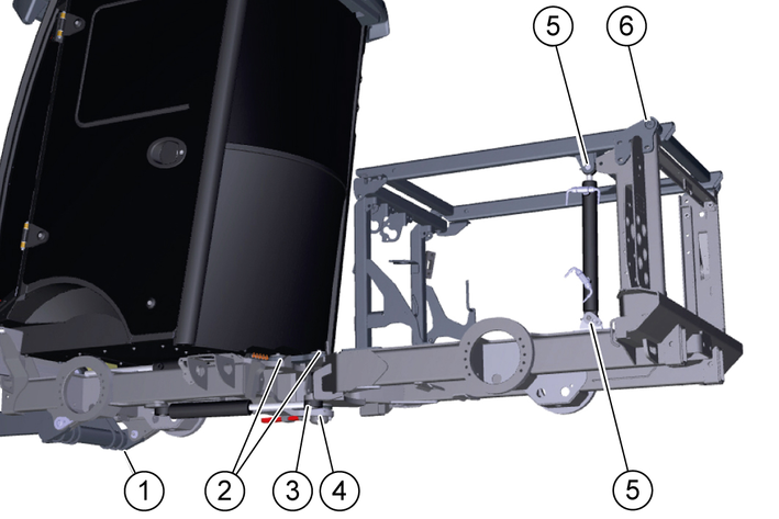
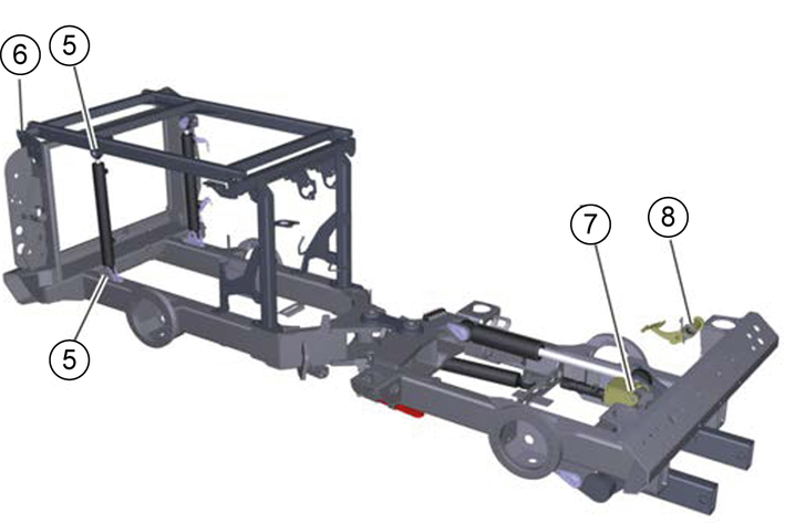
Lubrication point | Number of lubrication points | Lubrication interval | |
|---|---|---|---|
1 | Front power lifter slew bearing and lifting cylinder | 1 each |
|
2 | Articulated steering at centre of vehicle | 2 |
|
3 | Steering cylinder | 2 |
|
4 | Lower articulated joint bearing | 1 |
|
5 | Lifting cylinder | 4 |
|
6 | Lifting platform | 2 |
|
7 | Accelerator pedal | 1 |
|
8 | Brake pedal deflection lever | 1 |
|
Malfunctions
Keep the V-belt clean and free of grease.
Use high-grade multi-purpose grease.
Lubricate the grease nipples in accordance with the lubricating intervals (Table) using a grease gun.
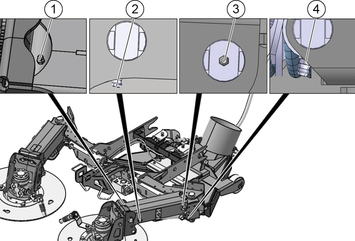
Lubrication point | Number of lubrication points | Lubrication interval | |
|---|---|---|---|
1 | Brush head lifting arm axle | 1 each | Every 8 h |
2 | Cylinder lifting arm axle | 1 each | Every 8 h |
3 | Swivel bearing lifting arm axle | 1 each | Every 8 h |
4 | Swivel bearing cylinder axle | 1 each | Every 8 h |
Malfunctions
Keep the V-belt clean and free of grease.
Use high-grade multi-purpose grease.
Lubricate the grease nipples in accordance with the lubricating intervals (Table) using a grease gun.
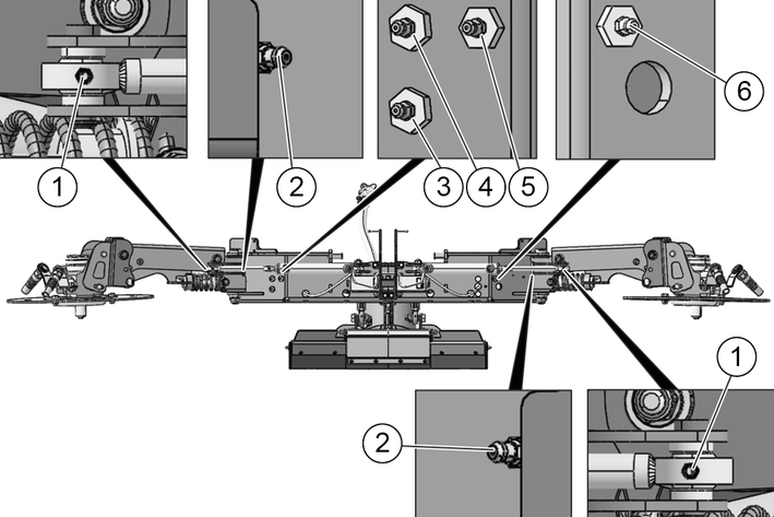
Lubrication point | Number of lubrication points | Lubrication interval | |
|---|---|---|---|
1 | Swivelling cylinder lifting arm axle | 1 each | Every 8 h |
2 | Swivel bearing base support axle | 1 each | Every 8 h |
3 | Suction mouth cylinder support | 1 | Every 8 h |
4 | Suction mouth cylinder basic body | 1 | Every 8 h |
5 | Swivelling cylinder base support axle | 1 | Every 8 h |
6 | Swivelling cylinder base support axle | 1 | Every 8 h |
Park the vehicle on a level surface.
Switch off the suction fan.
Lower the side brushes.
Apply the parking brake.
Secure the vehicle against rolling away.
Switch off the ignition and remove the ignition key.
Risk of fatal injury from flowing road traffic
Bring the vehicle out of the hazard zone of flowing road traffic before starting any repair work.
Switch on the warning flashers.
Erect a warning triangle.
Don warning clothing.
Risk of injury and damage
Engine continues to run after switch-off.
Wait 5 seconds after switching off the engine.
Be sure to keep away from the working area during this period.
Risk of damage through incorrect cleaning
The articulated joint, tyres, radiator fins, hydraulic hoses and valves, seals, electrical and electronic components must not be cleaned using a high-pressure cleaner.
Observe the respective safety regulations when cleaning the vehicle with a high-pressure cleaner.
Do not use aggressive cleaning agents.
Wash the vehicle only when the engine is switched off to protect the air filter.
Risk of injury and damage
The vehicle may start up unexpectedly.
Always remove the ignition key and disconnect the battery before performing any maintenance or cleaning work.
Risk of injury and damage
Maintenance work on the hydraulic system may only be performed by specially trained personnel.
Risk of injury and damage
Always secure the tipping mechanism.
Danger of injury
Fully tip the waste container and lower the brush system/attachment unit to relieve the hydraulic system of pressure during all maintenance work.
The waste container can pivot to the rear. Always completely lower the waste container to the end position before performing work underneath the waste container.
The waste container can lower unintentionally. Perform work on the turbine only when the waste container is fully raised.
Danger of burns
Allow the vehicle to cool down sufficiently.
Do not touch any hot components of the hydraulic system, hydrostatic drive motor, internal combustion engine or the exhaust system.
Environmental pollution
Do not allow fluids such as engine oil, hydraulic oil, brake fluid, diesel or coolants to flow into the ground. Please protect the environment and dispose of liquids in an environmentally-friendly manner.
Risk of injury and damage
Always secure the waste container when working with a raised waste container.
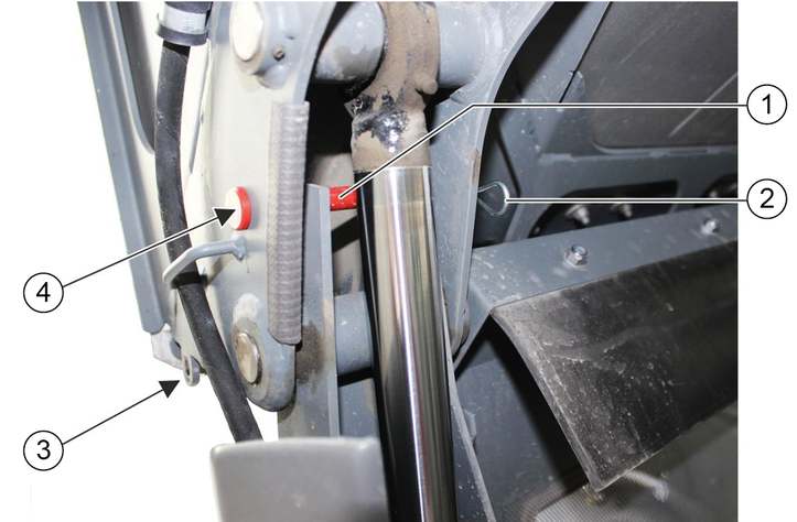
When the waste container is raised, use safety bolts and secure with the safety brackets (2x).
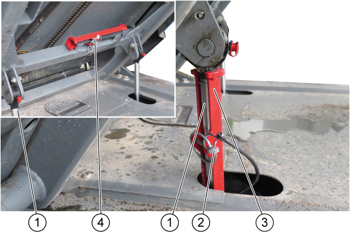
Raise the tipping device all the way.
Open the locking pin.
Remove the support from the bracket.
Insert the bracket.
Fit the locking pin.
Locking pins can be applied to the left and right piston rods.
Damage to the suction hose
When lowering the tilting frame, make sure that the suction hose goes into its guide properly.
Lower the tilting frame after removing the safety support.
If necessary, manually insert the suction hose into the guide.
Risk of burns!
Allow the vehicle to cool down sufficiently before removing any panels.
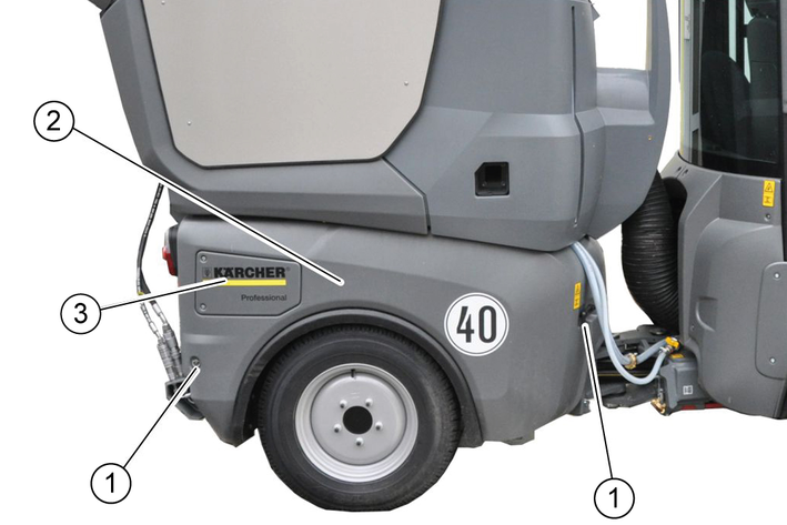
Remove the switchover valve cover.
Set the switch lever to the "Lifting platform" position, see chapter Waste container/attachment frame switchover.
Raise the lifting platform approx. 15 cm.
Open both side cladding locks.
Lift the side cladding upwards and take it off sideways.
Installation is performed in reverse sequence.
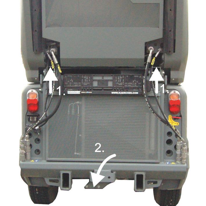
Lift the radiator protective grille upwards.
Pull out the lower part.
Remove the radiator protective grille downwards.
Engage the radiator protective grille at the bottom, then snap shut at the top.
Risk of burns on account of hot components
Do not open or touch the radiator or parts of the cooling system while the motor is hot.
Damage to property due to incorrect coolant
Only top up coolant when the motor is cool.
Use water-based anti-freeze.
Do not mix different anti-freeze types.
Only used softened water.
For coolant refer to chapter Technical data.
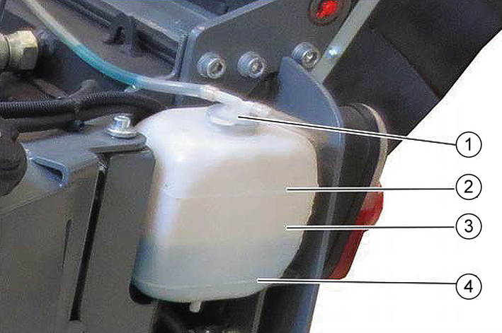
Check the filling level when the engine is cold.
Remove the left side panel.
Check the filling level in the expansion reservoir.
Note
The coolant level must be between the upper and lower markings.
Top up the coolant if necessary.
Also check the filling level in the radiator, see chapter Topping up the coolant in the radiator.
If the expansion reservoir is totally empty, top up the radiator first.
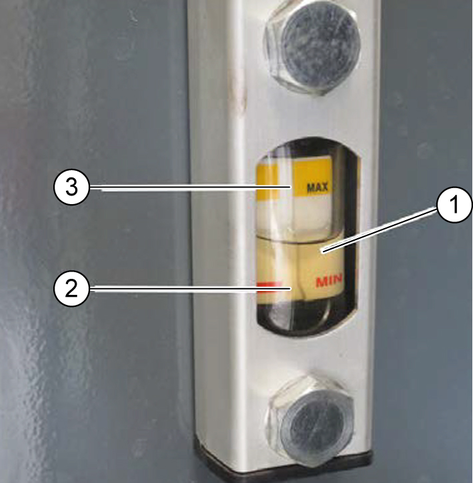
Check the hydraulic oil level.
Note
The hydraulic fluid must be between the upper and lower markings.
Top up the hydraulic oil if necessary.
Note
Lacking hydraulic oil can be topped up using a special accessory tool connected to the leakage coupling on the vehicle. If required, request the order no. at Kärcher or have Kärcher Customer Service do the topping up.
For the hydraulic oil grade, see chapter Technical data.
Risk of burns on account of hot components
Do not open or touch the radiator or parts of the cooling system while the motor is hot.
Damage to property due to incorrect coolant
Only top up coolant when the motor is cool.
Use water-based anti-freeze.
Do not mix different anti-freeze types.
Only used softened water.
For coolant refer to chapter Technical data.
Remove the waste container, see chapter Removing the waste container
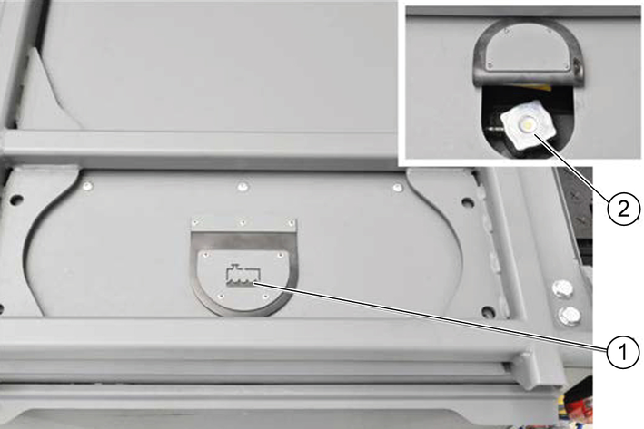
Tilt up the radiator cap cover.
Turn the radiator cap one click and allow the pressure in the radiator to release.
Unscrew the radiator cap when the radiator has depressurised.
Slowly fill the radiator all the way to the top without air bubbles.
Screw the radiator cap on tight.
Refill the coolant expansion reservoir. See chapter Checking the coolant level and topping up the coolant.
Reattach the panel.
Danger of injury
Observe the safety regulations on the handling of batteries.
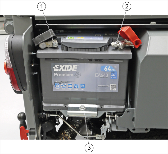
Fit the battery into the battery holder.
Screw the bracket on the battery base tight.
Connect the terminal clamp (red cable) to the plus terminal (+).
Connect the terminal clamp (black cable) to the minus terminal (-).
Plug the cover caps onto the terminal clamps.
CAUTION
Always disconnect the minus terminal first when removing the battery.
Check that the battery terminals and terminal clamps are protected with a sufficient quantity of terminal grease.
Risk of injury!
Only charge the battery with the appropriate charger.
Observe the safety instructions on the handling of batteries.
Follow the operating instructions of the charger manufacturer.
Disconnect the minus terminal at the battery.
Connect the charger to the battery.
Insert the mains plug and switch on the charger.
Charge the battery with as small a charging current as possible.
After charging, first disconnect the charger from the mains and then from the battery (minus pole first).
Reconnect the battery.
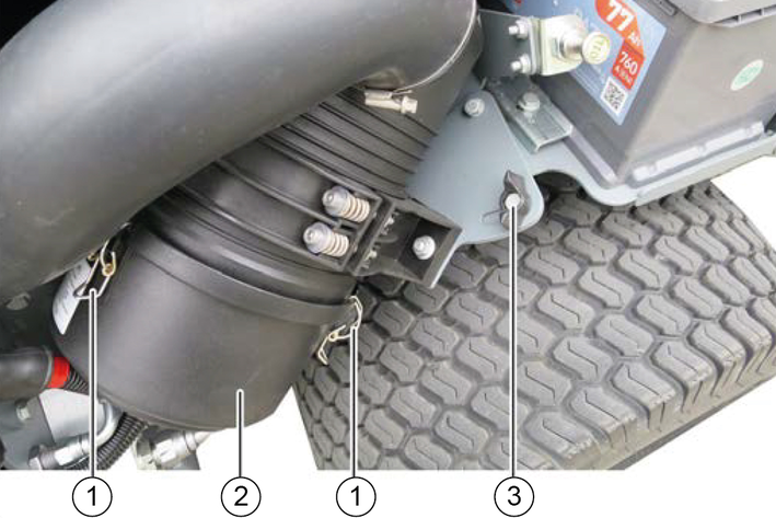
Remove the right-hand side motor cladding.
Unscrew the wing screw approx. 2 turns
Pivot the complete air filter unit outwards as far as it will go.
Screw the wing screw tight.
Open the locks (3x) on the air filter housing.
Remove the air filter housing.
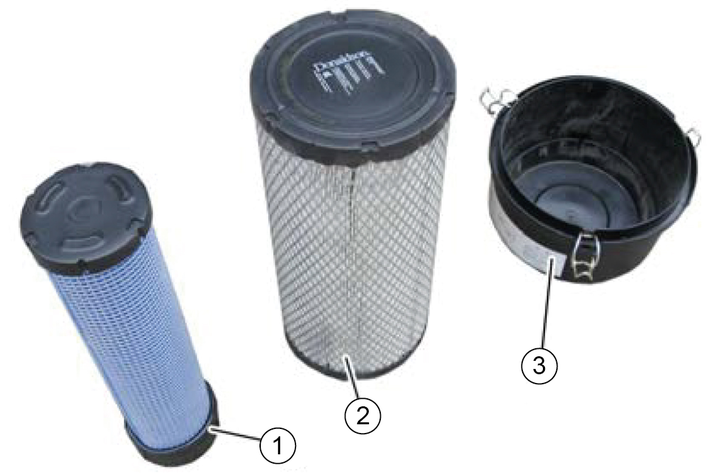
Pull out the filter cartridge and safety cartridge.
Clean the entire interior of the air filter housing.
Knock the dust out of the filter cartridge on a hard surface.
Do not blow out the filter cartridge with compressed air.
Replace the safety cartridge with a new one.
Do not re-use a used safety cartridge.
Check that the filter cartridge and sealing surfaces are clean and undamaged.
Replace a heavily soiled or damaged filter cartridge with a new one.
After assembly, pivot the complete air filter unit inwards and tighten it using the wing screw.
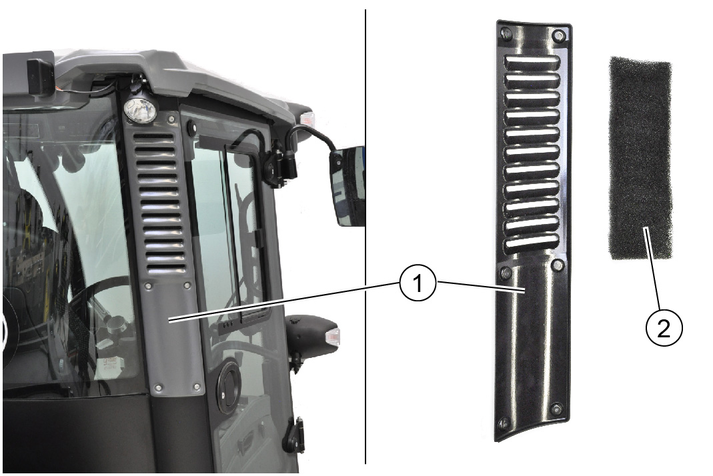
Fine filter filter grade F8 (available as option)
Unscrew the 6 screws for the cover.
Remove the cover.
Take out the dust filter.
Blow out the slightly contaminated dust filter using compressed air (reduced pressure). Renew severely contaminated dust filter.
Insert the new or cleaned filter.
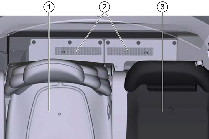
Push both seats forwards.
Remove the dust filter.
Check/clean the dust filter, replace if necessary.
Ensure the correct mounting position on re-installation.
Risk of fatal injury from flowing road traffic
Bring the vehicle out of the hazard zone of flowing road traffic before starting any repair work.
Switch on the warning flashers.
Erect a warning triangle.
Don warning clothing.
Note
Use a suitable, commonly available jack.
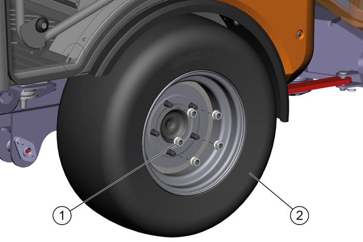
Park the vehicle on level and solid ground.
Engage the parking brake and additionally secure the vehicle against rolling away.
Secure the articulated joint.
Remove the ignition key.
Use a suitable tool to release the wheel nuts by approx. 1 turn.
Fit the jack to the appropriate mounting point at the front or rear wheel and raise the vehicle with the jack.
Additionally support the vehicle with axle stands or blocks.
Unscrew the wheel nuts.
Remove the wheel.
Fit the new wheel and tighten all wheel nuts in a diagonal sequence all the way to their end stops.
Tighten the wheel nuts to a torque of 180 Nm.
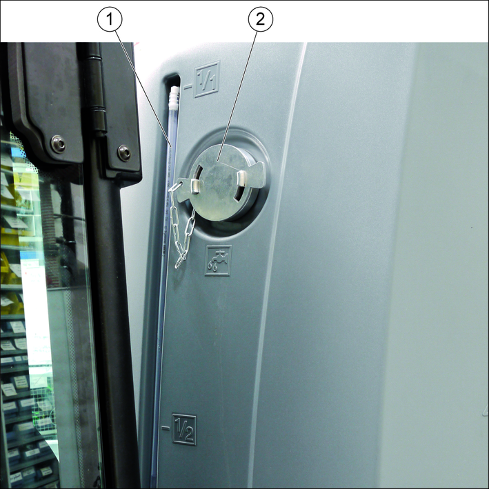
Open the lock of the filling nozzle.
Attach the filling hose to the filling nozzle.
Fill the water reservoir.
Remove the filling hose and close the filling nozzle lock.
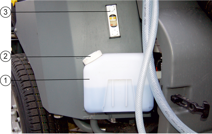
Adhere to the manufacturer information for the wiping water and antifreeze.
Raise the attachment frame.
Unlock and remove the side panels.
Remove the lid from the wiping water container.
Fill with wiping water.
Also add antifreeze in the case of potential frost.
Fit the lid on the wiping water container.
Attach the side panels again.
Danger of burns
Do not touch any hot surfaces such as engines, motors or gearboxes.
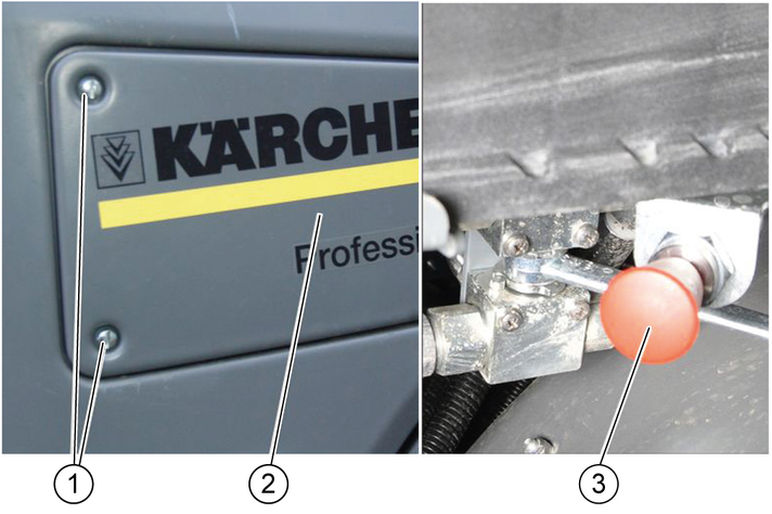
Park the vehicle on a level surface.
Unscrew the screws.
Remove the cover.
Pull out the oil dipstick.
Wipe the oil dipstick and insert it.
Pull out the oil dipstick.
Measure the oil level using the oil dipstick.
The oil level must lie between the "MIN" and "MAX" markings.
Top up with engine oil if the oil level is below the "MIN" marking.
Danger of burns
Do not touch any hot surfaces such as engines, motors or gearboxes.
Risk of damage
An excessive high oil level leads to engine damage.
If the oil is above the "MAX" marking, drain oil until reaching the correct oil level.
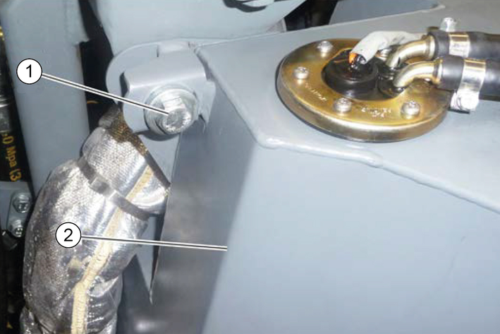
Fuel tank fastener
Fuel tank
Remove the left-hand side motor cladding.
Unscrew the fuel tank fastener screw and pivot the fuel tank outwards.
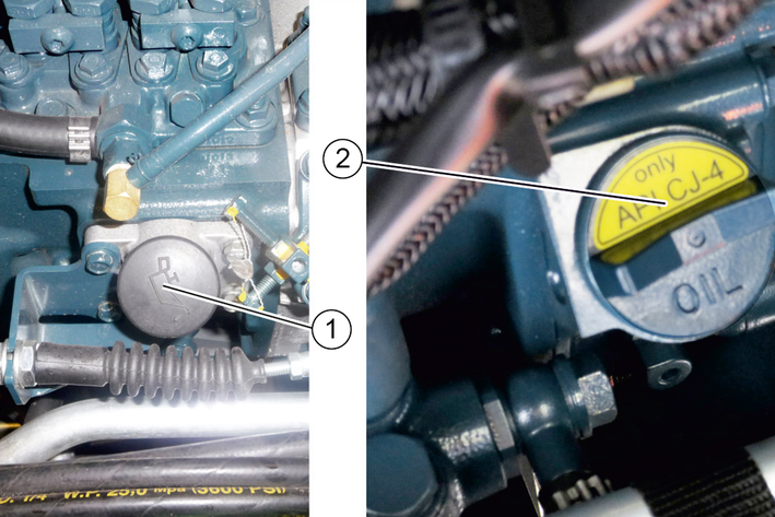
Filler cap
MC 130 advanced plus filler cap
Check the engine oil level, see chapter Checking the engine oil level.
Open the filler cap.
Top up the engine oil.
For the engine oil specifications, see chapter Technical data.
Do not fill the engine above the "MAX" marking.
Close the filler cap.
Check the engine oil level again after 5 minutes.
Top up the engine oil if necessary.
Danger of burns
Allow the vehicle to cool down sufficiently before changing the engine oil and engine oil filter.
The engine oil is easier to drain when the engine is warm.
Switch off the engine.
Place a catch pan (min. 10 litres) underneath.
Unscrew the oil drain plug.
Unscrew the filler cap.
Drain oil.
Unscrew the oil filter.
Clean the mounting and sealing surfaces.
Coat the seal of the new oil filter with oil.
Screw in the oil filter and hand-tighten.
Screw in the oil drain plug (tightening torque 60 Nm).
Pour in the engine oil.
Close the filler cap.
Allow the engine to run for 30 seconds.
Wait 5 minutes.
Check the oil level.
Renew the seals.
Check for leaks.
Air must be bled from the fuel system if the fuel tank has been run empty of the fuel filter has been changed.
Fill the fuel tank.
Set the ignition switch to position I.
The pump runs audibly quieter after 2-5 minutes.
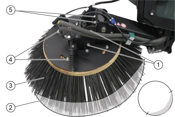
Raise the side brushes.
Release the nuts.
Remove the side brush.
Fit the new side brush and screw in place.
Adjusting the sweeping area
Adjust the sweeping pattern according to the illustration using the rear and side screws.
Disconnect the water circulation system hose coupling.
Connect the water supply hose to the water circulations system and flush the system.
Set the irrigation switch to the water circulation system position
The end of the suction pipe is better irrigated.
Open the valve on the drain hose (on the left under the waste container).
Allow the water to drain.
Risk of injury and damage
Always secure the tipping mechanism.
Park the vehicle on a level surface.
Switch off the ignition and remove the ignition key.
Apply the parking brake.
Switch off the main switch.
Clean the vehicle daily after finishing work.
Risk of damage through incorrect cleaning
The articulated joint, tyres, radiator fins, hydraulic hoses and valves, seals, electrical and electronic components must not be cleaned using a high-pressure cleaner.
Observe the respective safety regulations when cleaning the vehicle with a high-pressure cleaner.
Do not use aggressive cleaning agents.
Wash the vehicle only when the engine is switched off to protect the air filter.
To avoid a risk of fire, check the vehicle for escaping oil and fuel. Have leaks repaired by Customer Service.
Clean all plant residues and oil from the engine, muffler, battery and fuel tank to avoid a risk of fire.
If necessary, clean the engine with a brush, compressed air or with low water pressure if necessary.
Clean the wheel mudguards.
Remove the radiator protective grille, see chapter Removing/installing the radiator protective grille.
Manually remove coarse dirt deposits from the engine radiator, air-conditioner radiator and fuel cooler.
Clean the engine radiator, air-conditioner radiator and fuel cooler with a soft brush, compressed air (max. 5 bar) or with low water pressure.
Waste container is emptied.
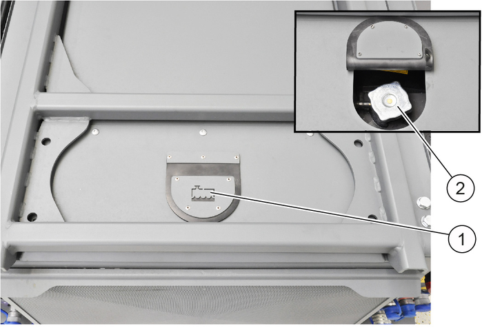
Raise the waste container.
Remove the locking pins from the diffusor grille.
Clean the waste container and the cover with a water jet.
Clean the area behind the waste water sieve with a water jet.
The waste container must be raised.
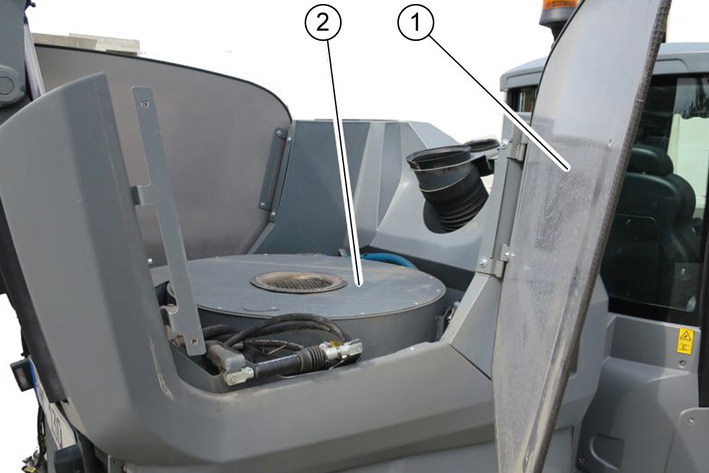
Secure the waste container.
Pivot out the side cover.
Remove dirt from the fan grille and clean with a moist cloth.
Waste container emptied.
Motor running.
Damage due to soiled vacuum system
A soiled vacuum system can lead to the blower fan running out-of-round and to vehicle vibrations.
Check the vacuum system for soiling and clean if necessary.
Switch on the PTO.
Set the motor speed to approx. 2200 rpm
Switch on the blower fan.
Using a water hose, spray fresh water into the suction mouth area.
The water is collected in the waste container. The cleaning process is completed when clean water exits at the diffuser.
Empty waste container.
Keep running the blower to dry the waste container.
Contact Customer Service if, in spite of thorough cleaning, vibrations are still present (caused by the suction blower running out-of-round).
Raise the waste container with attachment frame, see chapter.Waste container/attachment frame switchover
Unscrew the filter casing.
Clean the water filter.
Insert the filter.
Check for correct seating.
Screw the filter casing tight.
The spray nozzles are located on the side brushes and suction mouth.
Remove the spray nozzles.
Clean the spray nozzles with a brush/compressed air.
Install the spray nozzles.
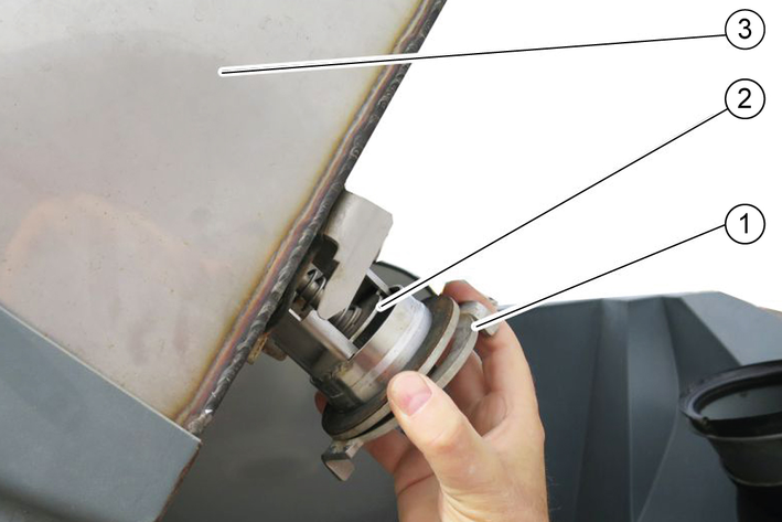
Empty the waste container.
Raise the waste container.
Open the bayonet connection.
Remove the valve.
Clean the valve under running water.
Insert the valve.
Close the bayonet connection.
The fuses are located behind a cover behind the driver's seat.
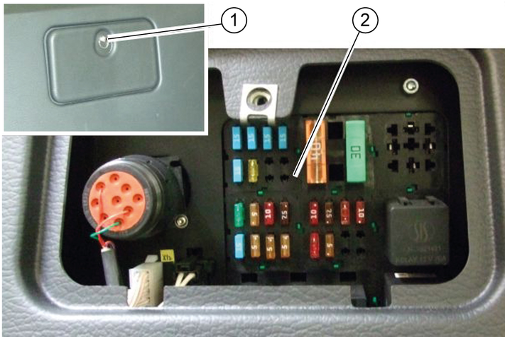
Open cover.
Replace defective fuses.
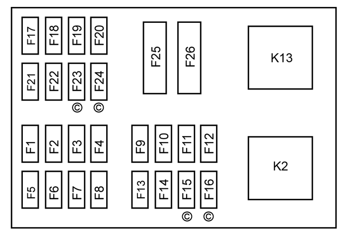
Use only fuses with the same ampere rating.
Fuse | Function | A |
|---|---|---|
F1 | Fuel valve CR* control unit | 30 |
F2 | BODAS control unit, display | 5 |
F3 | Limiter lamp Interior lighting | 10 |
F4 | Spray pump | 7.5 |
F5 | Warning flasher system | 15 |
F6 | Rear fog lamp | 5 |
F7 | Left limiter lamps | 5 |
F8 | Right limiter lamps | 5 |
F9 | Windscreen wiper Differential lock | 10 |
F10 | Radio High-pressure cleaner | 7.5 |
F11 | Travel direction indicator | 10 |
F12 | Flashing beacon | 10 |
F13 | Driving pump, indicator | 7.5 |
F14 | Motor | 5 |
F15 | CR* exhaust gas return valve | 5 |
F16 | CR* air volume sensor | 5 |
F17 | Headlights | 15 |
F18 | Work lights | 15 |
F19 | Cabin ventilation | 15 |
F20 | Seat heater Mirror heater | 15 |
F21 | Cabin accessories Front connector, attached equipment | 15 |
F22 | Seat compressor Rear connector, distributor | 30 |
F23 | Start switch (ignition switch) | 5 |
F24 | Windscreen heater | 30 |
F25 | Preheating | 40 |
F26 | BODAS control unit | 30 |
F31 | Main fuse at the engine | 70 |
* CR = Common Rail motor (MC 130 Advanced plus) | ||
Risk of injury and damage
Note the weight of the device.
Park the vehicle in a safe, level and dry place, leave the main switch on.
Change the motor oil and the oil filter.
If frost is expected, check if there is enough antifreeze in the coolant.
Empty the water container and the pipe system.
With a recycling system (option), drain the water out of the waste container.
Switch off at main switch.
Clean the inside and outside of the vehicle.
Jack up the vehicle if it is in storage for more than one month.
Disconnect battery.
You can remedy minor faults using the following overview.
If in any doubt, please contact your authorised Customer Service.
Risk of electric shock
Switch off the vehicle before carrying out any care and maintenance work, and remove the key.
Repair work and work on electrical components must only be performed by your authorised Customer Service.
In case of all malfunctions not listed, contact Customer Service!
Cause:
Remedy:
Check / charge the battery.
Switch on the main switch.
Sit in the driver's seat (seat contact switch is activated).
Set the driving direction lever to the NEUTRAL position - central position.
Fill up fuel, bleed the fuel system.
Check, clean and/or replace the fuel filter.
Check the fuel connections and lines.
Contact an authorised Customer Service department.
Cause:
Remedy:
Clean/replace the air filter.
Check, clean and/or replace the fuel filter.
Fill up fuel, bleed the fuel system.
Check the fuel connections and lines.
Contact an authorised Customer Service department.
Cause:
Remedy:
Release the parking brake.
Check the position of the neutral lever.
Have the oil level of the drive hydraulics checked by Customer Service.
In the event of freezing temperatures and cold hydraulic oil: Allow the device to warm up for at least 3 minutes.
Cause:
Remedy:
Close the fuel cock at the fuel filter.
Unplug the fuel supply pump.
In the event of repeated occurrences, contact Customer Service.
Cause:
Remedy:
Empty the waste container.
Switch on the suction fan.
Check the hose on the suction fan.
Check / replace the seals:
Suction fan sealing collar.
Filter chamber seal.
Waste container seals.
Check / clean / replace the dust filter.
Check that the dust filter is firmly in place.
In case of light soiling, clean the dust filter.
In case of damage or heavy soiling, replace the dust filter.
Check the sealing strips for wear / set / replace them.
Cause:
Remedy:
Check the roller brush and side brush for wear, replace them as necessary.
Check the sealing strips for wear, replace them as necessary.
Check that the coarse dirt flap is fully functional.
Check that roller brush halves are correctly in place.
Check the filling level of the hydraulic oil tank.
Check the hydraulic system for leaks.
Cause:
Remedy:
Contact Customer Service.
Cause:
Remedy:
Check the filling level of the hydraulic oil tank.
Check the hydraulic system for leaks.
Check the side brushes for any tangled pieces of tape.
Cause:
Remedy:
Contact Customer Service.
Cause:
Remedy:
Check / charge the battery.
Switch on the main switch.
Sit in the driver's seat (seat contact switch is activated).
Set the driving direction lever to the NEUTRAL position - central position.
Fill up fuel, bleed the fuel system.
Check, clean and/or replace the fuel filter.
Check the fuel connections and lines.
Contact an authorised Customer Service department.
Cause:
Remedy:
Clean/replace the air filter.
Check, clean and/or replace the fuel filter.
Fill up fuel, bleed the fuel system.
Check the fuel connections and lines.
Contact an authorised Customer Service department.
Cause:
Remedy:
Release the parking brake.
Check the position of the neutral lever.
Have the oil level of the drive hydraulics checked by Customer Service.
In the event of freezing temperatures and cold hydraulic oil: Allow the device to warm up for at least 3 minutes.
Cause:
Remedy:
Close the fuel cock at the fuel filter.
Unplug the fuel supply pump.
In the event of repeated occurrences, contact Customer Service.
Cause:
Remedy:
Empty the waste container.
Switch on the suction fan.
Check the hose on the suction fan.
Check / replace the seals:
Suction fan sealing collar.
Filter chamber seal.
Waste container seals.
Check / clean / replace the dust filter.
Check that the dust filter is firmly in place.
In case of light soiling, clean the dust filter.
In case of damage or heavy soiling, replace the dust filter.
Check the sealing strips for wear / set / replace them.
Cause:
Remedy:
Check the roller brush and side brush for wear, replace them as necessary.
Check the sealing strips for wear, replace them as necessary.
Check that the coarse dirt flap is fully functional.
Check that roller brush halves are correctly in place.
Check the filling level of the hydraulic oil tank.
Check the hydraulic system for leaks.
Cause:
Remedy:
Contact Customer Service.
Cause:
Remedy:
Check the filling level of the hydraulic oil tank.
Check the hydraulic system for leaks.
Check the side brushes for any tangled pieces of tape.
Cause:
Remedy:
Contact Customer Service.
Cause:
Coolant temperature is too high.
Remedy:
Switch off the motor.
Clean the radiator (see chapter "Cleaning the radiator").
Check the level of coolant in the motor, refill as necessary.
If the warning light does not go out within 5 minutes:
Switch off the engine
Contact Customer Service
Cause:
Hydraulic oil temperature too high.
Remedy:
Operate the engine in idling mixture until the warning light goes out.
Cause:
Hydraulic oil temperature too low.
Remedy:
Carefully warm up the engine until the warning light goes out.
Cause:
Engine oil pressure is too high.
Remedy:
Call Customer Service.
Cause:
Parking brake active.
Remedy:
Release the parking brake.
Cause:
Low fuel level.
Remedy:
Top up the fuel.
Remedy:
Vent the fuel system if the tank was run dry.
Cause:
Battery is not charging.
Remedy:
Call Customer Service.
Cause:
Regeneration process required.
Remedy:
Perform regeneration (see chapter "Regeneration").
Cause:
Service required.
Remedy:
Have the device serviced by Customer Service.
The service display must be reset by Customer Service.
The following coded error messages can occur when operating the level V engines V2403-CR-TE4B-KRC-1 (MC 130 plus, MC 130 classic).
When an error is indicated while the engine is running, the indicator lamp flashes and an error code may also be shown on the display.
NCD error | Indicator lamp blinks |
|---|---|
U0076 | 1Hz (one second interval) + on for 5 seconds + 1 Hz (one second interval) + on for 5 seconds ... |
P0102 | 1Hz + on for 5 seconds + 1 Hz + on for 5 seconds ... |
PCD Error | Indicator lamp blinks |
|---|---|
P3014 | 1 Hz (1 second interval) |
P1A28 | 1 Hz (1 second interval) |
P3015 | 1 Hz (1 second interval) |
P2455 | 1 Hz (1 second interval) |
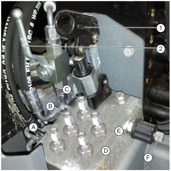
(A) - (E) 8mm screws
(F) Knurled screw
Remove the cover, then unlock the cover screws (3x) by turning to the left.
A pipe is required for operating the manual pump and this is located at the side behind the driver's seat.
An 8mm ring spanner to actuate the screws is included.
Unscrew the screws (B, E, F).
Actuate the manual pump (1).
Waste container/attachment frame raises.
Slowly screw in screw (F).
Waste container/attachment frame lowers.
Screw in the bolts.
Original position is restored.
Unscrew the screws (A, D, F).
Actuate the manual pump (1).
Front power lift/suction mouth raises.
Slowly screw in screw (F).
Front power lift/suction mouth lowers.
Screw in the bolts.
Original position is restored.
Move the ball tap (2) to the horizontal position.
Unscrew screw (C).
Actuate the manual pump (1).
Spring actuator releases.
Move the ball tap to the vertical position.
Screw in screw (C).
Spring actuator is actuated (original position).
Only use original accessories and original spare parts. They ensure that the appliance will run fault-free and safely.
Information on accessories and spare parts can be found at www.kaercher.com.
Order no. | Description | Quantity | Figure |
|---|---|---|---|
6.422-522.0 | LED working light | 2 |  |
9.654-350.0 | Wiper arm | 1 |  |
9.654-351.0 | Wiper blade | 1 |  |
9.989-357.0 | Signal horn | 1 |  |
9.656-126.0 | Air filter on hydraulic oil tank | 1 |  |
2.852-393.0 | Fine dust air filter | 1 |  |
6.996-448.0 | Light bulb | 2 |  |
7.651-027.0 | Lamp | 2 |  |
7.651-028.0 | Lamp | 2 |  |
Device performance data | |
Travel speed (max.) | 40 (30) km/h |
Working speed (max.) | 20 km/h |
Climbing ability (max.) | 25 % |
Driven wheels | 4 m2/h |
Theoretical surface performance | 24000 |
Working width | 1200 - 2400 mm |
Turning radius | 1173 mm |
Min. working width | 1200 mm |
Standard working width | 1540 mm |
Battery | |
Battery type | Maintenance-free - |
Battery capacity | 80 Ah |
Battery voltage | 12 V |
Dimensions and weights | |
Length | 3955 mm |
Width | 1540 mm |
Height | 2000 mm |
Net weight (transport weight) | 2275 kg |
Approved total weight | 3500 kg |
Maximum permissible front axle load | 2000 kg |
Maximum permissible rear axle load | 2000 kg |
Permissible braked trailer (option) load | 3000 kg |
Permissible unbraked trailer (option) load | 750 kg |
Trailer coupling (option) vertical load | 250 kg |
Waste container | |
Waste container volume (gross) | 1300 (1.3) l (m3) |
Discharge height (max.) | 1550 mm |
Water reservoir capacity | 195 l |
Side brush | |
Side brush diameter | 900 rpm |
Side brush speed (continuously variable) | 0 - 110 rpm |
Internal combustion engine | |
Engine type | Kubota V2403-CR-T-EW03 |
Type | 4-cylinder four-stroke diesel engine with diesel particle filter (DPF) |
Engine capacity | 2434 cm3 |
Cooling type | Water |
Engine power at 2700 rpm | 48.0 kW |
Engine oil type | Shell Rimula R6 LM 10W-40 |
Engine oil volume | max. 9.5 l |
Fuel tank capacity | 50 l |
Fuel type | Diesel l |
Coolant (SAE J814C) | Havoline XLC Antifreeze |
Hydraulic oil as per DIN 51524, Part 3 | Renol B HV 46 |
Hydraulic oil quantity | 43 l |
Determined values in acc. with EN 60335-2-72 | |
Sound level LpA | 74 dB(A) |
Uncertainty KpA | 3 dB(A) |
Sound power level LWA | 104 dB(A) |
Uncertainty KWA | 3 dB(A) |
Hand-arm vibration value | 0.4 m/s2 |
Uncertainty K | 0.2 dB(A) |
Seat vibration value | 0.5 m/s2 |
Uncertainty K | 0.1 dB(A) |
Grease | |
For manually lubricated lubrication points | Multi-purpose grease |
Device performance data | |
Travel speed (max.) | 40 (30) km/h |
Working speed (max.) | 20 km/h |
Climbing ability (max.) | 25 % |
Driven wheels | 4 m2/h |
Theoretical surface performance | 24000 |
Working width | 1200 - 2400 mm |
Turning radius | 1173 mm |
Min. working width | 1200 mm |
Standard working width | 1540 mm |
Battery | |
Battery type | Maintenance-free - |
Battery capacity | 80 Ah |
Battery voltage | 12 V |
Dimensions and weights | |
Length | 3955 mm |
Width | 1540 mm |
Height | 2000 mm |
Net weight (transport weight) | 2275 kg |
Approved total weight | 3500 kg |
Maximum permissible front axle load | 2000 kg |
Maximum permissible rear axle load | 2000 kg |
Permissible braked trailer (option) load | 3000 kg |
Permissible unbraked trailer (option) load | 750 kg |
Trailer coupling (option) vertical load | 250 kg |
Waste container | |
Waste container volume | - l (kg) |
Discharge height (max.) | - mm |
Water reservoir capacity | - l |
Side brush | |
Side brush diameter | - rpm |
Side brush speed (continuously variable) | - rpm |
Internal combustion engine | |
Engine type | Kubota V2403-CR-T-EW03 |
Type | 4-cylinder four-stroke diesel engine with diesel particle filter (DPF) |
Engine capacity | 2434 cm3 |
Cooling type | Water |
Engine power at 2700 rpm | 48.0 kW |
Engine oil type | Shell Rimula R6 LM 10W-40 |
Engine oil volume | max. 9.5 l |
Fuel tank capacity | 50 l |
Fuel type | Diesel (do not use Biodiesel) l |
Coolant (SAE J814C) | Havoline XLC Antifreeze |
Hydraulic oil as per DIN 51524, Part 3 | Renol B HV 46 |
Hydraulic oil quantity | 43 l |
Determined values in acc. with EN 60335-2-72 | |
Sound level LpA | 74 dB(A) |
Uncertainty KpA | 3 dB(A) |
Sound power level LWA | 104 dB(A) |
Uncertainty KWA | 3 dB(A) |
Hand-arm vibration value | 0.4 m/s2 |
Uncertainty K | 0.2 dB(A) |
Seat vibration value | 0.5 m/s2 |
Uncertainty K | 0.1 dB(A) |
Grease | |
For manually lubricated lubrication points | Multi-purpose grease |
The tyre pressures for various different axle loads and different speeds are listed in the following table.
 | Maxxis Vansmart A/S AL2 205/65C 8PR 107/105 TL All year tyres | ||||||||||
|---|---|---|---|---|---|---|---|---|---|---|---|
Axle load (kg) | 1000 | 1200 | 1400 | 1600 | 1800 | 1950 | |||||
Tyre pressure (bar) | 3.0 | 4.75 | |||||||||
 | Toyo 195/75 R14C 106/104 R Winter tyres (M + S) | ||||||||||
Axle load (kg) | 1000 | 1200 | 1400 | 1600 | 1800 | 2000 | |||||
Tyre pressure (bar) | 5.0 | ||||||||||
 | BKT LG306 26x12-12 8 PLY Grass tyres | |||||
|---|---|---|---|---|---|---|
Axle load (kg) | 1000 | 1200 | 1400 | 1600 | 1800 | 2000 |
Tyre pressure (bar) at 30 km/h | 1.0 | 1.0 | 1.3 | 1.6 | 2.0 | 2.4 |
Tyre pressure (bar) at 40 km/h | 1.0 | 1.1 | 1.5 | 1.8 | 2.2 | 2.6 |
 | Deestone D408 26x12-12.00 - 12 10 PLY Traction tyres | |||||
|---|---|---|---|---|---|---|
Axle load (kg) | 1000 | 1200 | 1400 | 1600 | 1800 | 2000 |
Tyre pressure (bar) at 30 km/h | 1.3 | 1.5 | 1.8 | 2.0 | 2.5 | 2.9 |
Tyre pressure (bar) at 40 km/h | 1.3 | 1.5 | 1.8 | 2.0 | 2.5 | 2.9 |
The protective covers can be adjusted to suit different tyre widths.
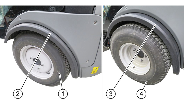
Release the screws, three each at the front.
Adjust the protective cover to suit the width of the tyres.
Unscrew the screws, three each at the rear.
Offset the protective cover.
Re-tighten all screws.
We hereby declare that the machine described below complies with the relevant basic safety and health requirements in the EU Directives, both in its basic design and construction as well as in the version placed in circulation by us. This declaration is invalidated by any changes made to the machine that are not approved by us.
Product: Sweeper
Type: PF-D
Currently applicable EU Directives2006/42/EC (+2009/127/EC)
2014/30/EU
2000/14/EC
Harmonised standards usedEN 13019
EN ISO 14982:2009
Conformity evaluation procedure used2000/14/EC: Annex V
Sound power level dB(A)PF-D (MC130)Measured: 101
Guaranteed: 104
The signatories act on behalf of and with the authority of the company management.

Documentation supervisor:
S. Reiser
Alfred Kärcher SE & Co. KG
Alfred-Kärcher-Str. 28 - 40
71364 Winnenden (Germany)
Ph.: +49 7195 14-0
Fax: +49 7195 14-2212
Winnenden, 2018/07/18