MC 250
59688300 (04/21)
59688300 (04/21)
Read the original instructions and the safety instructions before using your vehicle for the first time. Act in accordance with them.
Keep these operating instructions for future reference or for future owners.
Please report any defects or shipping damage identified on the vehicle when it is handed over directly to your dealer or department store.
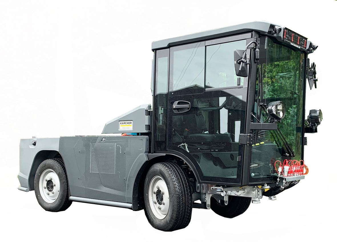
The following vehicles are described in these operating instructions:
Device carrier with VM motor (R754EU6C) 75 kW (Euro 6)
with DPF and SCR filters
Device carrier with VM engine (R754ISE5) 54.5 kW (Stage V)
with DPF filter
The following texts are excerpts from the operating instructions of the engine manufacturer.
(VM engine Euro 6)
The ATS system consists of a catalytic converter "Diesel Oxidation Catalyst (DOC) ", a particle filter"Diesel Particulate Filter (DPF) "and a catalytic converter"Selective Catalyst Reduction (SCR) ". These components burn the collected particles as part of a "regeneration process" and reduce the nitrogen oxides (NOx). Effective regeneration requires that the exhaust gases escape at a high temperature over a period of time. The exhaust gases must have a suitable temperature for regeneration, otherwise the DPF will continuously filter and thereby incurs a risk of becoming clogged. An actively regenerated post-treatment system is used to avoid clogging of the filter.
The exhaust gases of a diesel engine contain nitrogen oxides (NOx), which must be reduced. In accordance with pollutant emission standards, the current post-treatment system has been integrated with an "SCR" system.
The system for reducing the NOx gases consists of a dosing control unit (DCU Box), a tank for the reaction fluid DEF (Diesel Exhaust Fluid), a DEF injector and a catalytic converter SCR.
The liquid "Diesel Exhaust Fluid "(DEF) or known as AdBlue® as a trade name is pumped through the dosing control unit (DCU box) into the injector. The injector atomizes the liquid in front of the SCR catalytic converter, causing a chemical reaction. This chemical reaction converts the nitrogen oxides (NOx) contained in the exhaust gases into water vapour and nitrogen.
AdBlue® or DEF is a non-toxic, colourless, odourless and non-flammable liquid. It is poured into a special container in the vehicle and injected into the exhaust system to clean the exhaust gases.
The warranty conditions issued by our sales company responsible apply in all countries. We shall remedy any malfunctions on your vehicle within the warranty period free of charge, provided that a material defect or manufacturing flaw is the cause. In a warranty case, please contact your dealer (with the purchase receipt) or the next authorised customer service site.
Only use original accessories and original spare parts. They ensure that the appliance will run fault-free and safely.
Information on accessories and spare parts can be found at www.kaercher.com.
The vehicle may only be used for the intended use, as illustrated and described in these operating instructions.
Intended use also includes adherence to the prescribed servicing activities and intervals.
The vehicle and attachments may only be used, maintained and repaired by persons familiar with the vehicle and attachments and the associated hazards.
The legally applicable general safety and accident prevention regulations must be adhered to. All other safety regulations, occupational health care regulations and road traffic regulations must be adhered to.
The vehicle is not intended for use with a front loader.
The operating personnel must:
Be physically and mentally suitable
Have been instructed in the handling of the vehicle and attachments
Have read and understood these operating instructions and the operating instructions for any attachments or towed machinery
Have provided the operating company with verification of capability to operate the vehicle
Be explicitly nominated to operate the vehicle by the operating company
This vehicle is a device carrier that allows various attachments (not included in the scope of delivery) to be mounted at the front and rear of the vehicle.
This vehicle is suitable for work applications using various attachments, as well as for towing trailers.
Unbraked up to 600 kg, inertia-braked up to 3000 kg
The maximum trailer load to be towed is stated on the factory nameplate and must not be exceeded.
The vehicle must conform to the applicable national regulations if used on public roads.
Only attachments approved by KÄRCHER may be used.
KÄRCHER accepts no liability for accidents or malfunctions from non-approved attachments.
Observe the operating instructions for the attachments.
Driving licence: When driving on public roads, ensure that you have a valid driving license for this vehicle. If you have any questions, please contact the Kärcher Service.
Comply with the applicable national regulations.
Any type of improper use is prohibited.
The operating personnel are liable for hazards resulting from incorrect use. Usage for other purposes than those described in this documentation is prohibited.
No modifications must be made to the vehicle.
Do not remain in the hazard zone.
Never operate the vehicle in potentially explosive environments.
Never transport persons with the vehicle (except in the seats provided), on the loading area or on the attachments.
Do not use the vehicle in the forestry industry.
Do not use the vehicle for dispersing insecticide, pesticide or fertiliser.
The engine cover is not suitable as a cargo bed. Standing on the cover is also prohibited.
 Components such as batteries, rechargeable batteries or oil that pose a potential hazard to human health and the environment if handled incorrectly or disposed of incorrectly must not be disposed of with household rubbish.
Current information on content materials can be found at: www.kaercher.de/REACH
Observe the national regulations at the location.
Observe company-specific specifications.
Dispose of any operating and auxiliary materials according to the valid safety data sheets.
Vehicles that are no longer fit for service contain valuable recyclable materials. We recommend you cooperate with a waste management company with regard to the disposal of your vehicle.
Indication of an imminent threat of danger that will lead to severe injuries or even death.
Indication of a potentially dangerous situation that may lead to severe injuries or even death.
Indication of a potentially dangerous situation that may lead to minor injuries.
Indication of a potentially dangerous situation that may lead to damage to property.
Risk of asphyxiation. Keep packaging film out of the reach of children.
Only use the vehicle for its proper use. Take into account the local conditions and beware of third parties, in particular children, when working.
Persons with reduced physical, sensory or mental capabilities, or those with a lack of experience and knowledge, are only allowed to use the vehicle if they are supervised or have been instructed with respect to using the appliance safely, and understand the resultant dangers involved.
Only people who have been instructed on how to use the vehicle, or have proven their ability to operate it, and have been explicitly instructed to use it, must use the vehicle.
Children must not operate the vehicle.
Children must be supervised to prevent them from playing with the vehicle.
Safety devices are provided for your own protection. Never modify or bypass safety devices.
Danger of tilting if hill or slope is too steep! Observe the maximum permissible values in the technical data when driving up hills and slopes.
Danger of tilting in case of excessive tilting at side! Observe the maximum permissible values in the technical data when driving lateral to the travel direction.
Danger of tipping on unstable surfaces! Only use the vehicle on stable surfaces.
Risk of accident due to not adapting speed. Approach corners slowly.
The list on the risk of overturning is not necessarily comprehensive.
Driver cabins are equipped with air exit slats. Always keep these free from obstructions to ensure sufficient ventilation.
Ensure free visibility on public roads before use (e.g. fog-proof windscreens, mirrors, etc.).
Diesel engine: Never operate vehicles with diesel engines in confined spaces.
Danger of poisoning: Do not inhale the exhaust gases.
Never close off the exhaust gas openings.
Never bend down over the exhaust gas opening. Never reach inside the exhaust gas opening.
Always keep away from the drive area. Be aware of the engine after-running time after switching off (3-4 seconds).
Switch off the engine and remove the ignition key before performing cleaning or maintenance work on the vehicle, replacing parts or changing the functionality of the vehicle.
Repairs may only be carried out by approved customer service sites or staff qualified in this area who are familiar with all relevant safety instructions.
Adhere to the safety checks according to the applicable local regulations for mobile commercial vehicles.
Do not clean the tyres, radiator fins, hydraulic hoses and valves, seals, electrical and electronic components using a high-pressure cleaner.
Pay attention to the correct tyre inflation pressure, an excessively high tire inflation pressure can cause the tyre to burst.
Only original Kärcher seats may be used. Otherwise the vibration values cannot be guaranteed.
The vehicle has a hydrostatic drive, 2-wheel steering and a selectable 4-wheel steering. It therefore exhibits driving characteristics that are different to those of a car.
Braking characteristicsThe brake pedal must be pressed in order to brake.
Releasing the accelerator pedal provides no noticeable braking effect.
The vehicle has 2-wheel steering and selectable 4-wheel steering.
The 2-wheel steering is activated by default when starting the vehicle (driving mode).
The 4-wheel steering can be selected as desired (working mode).
The 4-wheel steering allows a tighter cornering than with 2-wheel steering.
Avoid fast steering movements and drive slowly in bends. Take the swinging at the rear into account.
Rear attachments and load statuses influence the vehicle's centre of gravity and the driving characteristics. You must be ready to adjust to changed driving characteristics, particularly after changing attachments and in the case of changeable load statuses. Limit ranges may be reached earlier.
The factory nameplates are in the direction of travel on the right, inside the driver cabin next to the driver's seat.
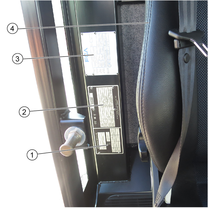
Frame factory nameplate
Vehicle factory nameplate
Engine factory nameplate
Driver's seat
The chassis number is located on the right side of the frames in the direction of travel, in the area of the front wheel.
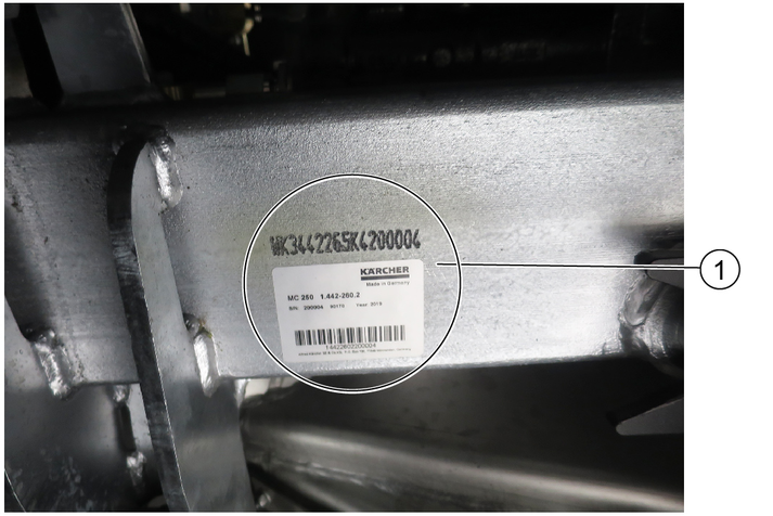
Chassis number
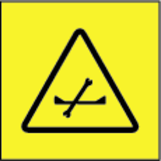
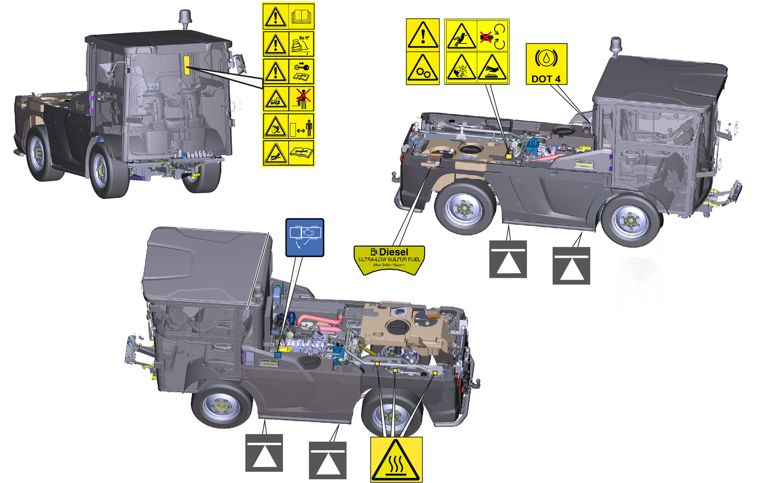
Immediately replace illegible or absent symbols.
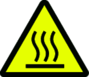 | DANGERRisk of burns from hot surfaces Allow the vehicle to cool down before working on it. |
 | DANGERRisk of burns due to hot exhaust pipe Do not touch the exhaust pipe. Before working, allow the exhaust pipe to cool down. |
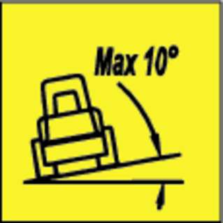 | DANGERDanger of tilting Only drive on terrain with a maximum lateral incline of 10°. |
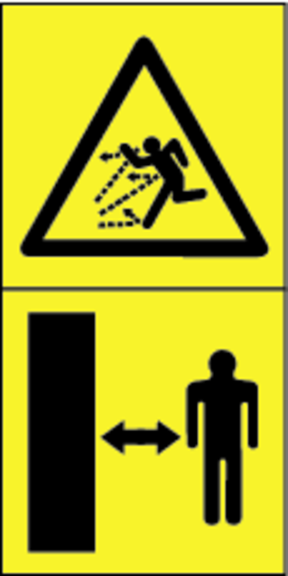 | DANGERRisk of injury on account of splashing objects Keep an adequate distance from persons, animals and objects. |
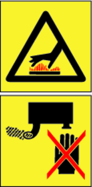
 | WARNINGRisk of injury Risk of being squeezed or hurt at the belts, side-brushes, waste container, cover. |
 | DANGERRisk of crushing When using the vehicle as a tractor, make sure that there are no persons between the vehicle and the trailer during operation. |
 | ATTENTION
Rotating machine parts. |
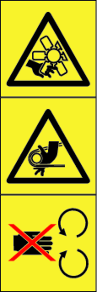 | DANGERRisk of injury from rotating parts Open the bonnet only when the motor has come to a halt. |
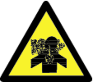 | WARNINGHealth risk due to poisonous exhaust gases Do not inhale exhaust gases. |
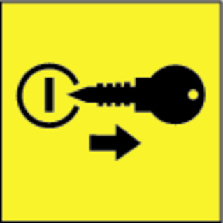 | DANGERRisk of injury due to unauthorised usage Remove the ignition key to protect against unauthorised use and prior to cleaning and maintenance work. |
 | ATTENTIONSafety for cleaning and maintenance Prior to cleaning and maintenance work, park the vehicle on a level and firm subsurface. |
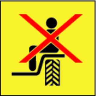 | DANGERDanger of injury due to use of unspecified locations for seating Sit exclusively on the driver’s seat. |
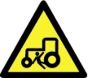 | DANGERRisk of injury due to rolling over No persons may be present in the vicinity of the vehicle during use. |
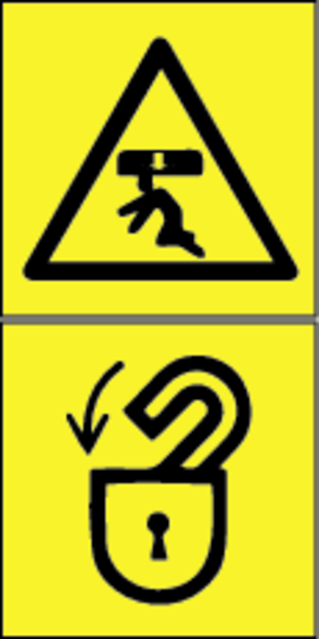 | DANGERRisk of impact, risk of crushing When transporting or working under suspended loads, use suitable means for supporting. |
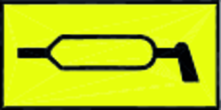 | Lubrication point |
 | Use DOT 4 brake fluid |
 | Refuel with diesel according to DIN EN 590 |
 | Attachment point for jack |
 | Open the engine cowling |
 | Read operating instructions |
Immediately replace illegible or absent symbols.
Safety devices protect the user and may not taken out of operation or functionally circumvented.
Adhere to the safety instructions in the chapters!
Requirements for starting the engine:
Driver is sitting on the driver's seat
Neutral position of the travel direction selector switch
If the travel direction selector switch is in the forward or reverse direction when starting the engine, the engine can still be started, but driving is only possible if the direction switch is first brought to the neutral position.
Operate the battery disconnector relay switch. See "Battery disconnector relay switch" chapter.
When the driver's seat is vacant:
The vehicle cannot be driven.
The front PTO cannot be switched on or off.
The parking brake requires hydraulic pressure to release. The brakes are automatically actuated when the engine is switched off.
The parking brake is also applied when the engine is running and the travel direction lever is in the NEUTRAL position.
The "Parking brake applied" warning light in the multifunction display lights up when the parking brake is applied.
The operator is protected from lightning strikes when sitting in the driver cabin.
The driver cabin has a roll-over protection structure (ROPS), which prevents rolling over after tipping over.
The driver cabin does not have a structure providing protection from falling objects (FOPS).
The driver cabin does not have a structure providing protection from falling objects (OPS).
Always use the safety belt.
Only use the batteries and chargers recommended by the manufacturer
Only replace batteries with batteries of the same type.
Before disposing of the vehicle, remove the battery and dispose of it in accordance with national or local regulations.
Observe the following warnings when handling the batteries:
 | Observe notes in the instructions for the battery, on the battery and in these operating instructions. |
 | Wear eye protection. |
 | Keep acids and batteries away from children. |
 | Risk of explosion |
 | Fire, sparks, open flames and smoking are prohibited. |
 | Risk of acid burns |
 | First aid. |
 | Warning |
 | Disposal |
 | Do not throw batteries in the bin. |
Risk of fire and explosion
Do not place tools or other objects on the battery.
Naked flames and smoking must be strictly avoided.
Ensure the room is well ventilated when charging batteries.
Only use batteries and chargers approved by Kärcher (original spare parts).
Environmental risk due to improper disposal of batteries
Ensure that defect or used batteries are disposed of safely (contact a waste management company or Kärcher Service).
When used normally, and when observing the instructions, lead-acid batteries do not pose any risk.
However, keep in mind that lead-acid batteries contain sulphuric acid which can cause serious chemical burns and corrosion.
If there is spillage or, if the battery is leaking, acid is escaping, lay down a binding agent such as sand. Do not let it reach the sewer system, soil or a body of water.
Neutralise the acid with lime/baking soda and dispose of it according to local regulations.
Contact a waste management company to dispose of faulty batteries.
Rinse out your eyes or rinse off your skin with copious amounts of fresh water if acid splashes into your eyes or onto your skin.
Then consult a doctor immediately.
Wash any contaminated clothing with water.
Change clothes.
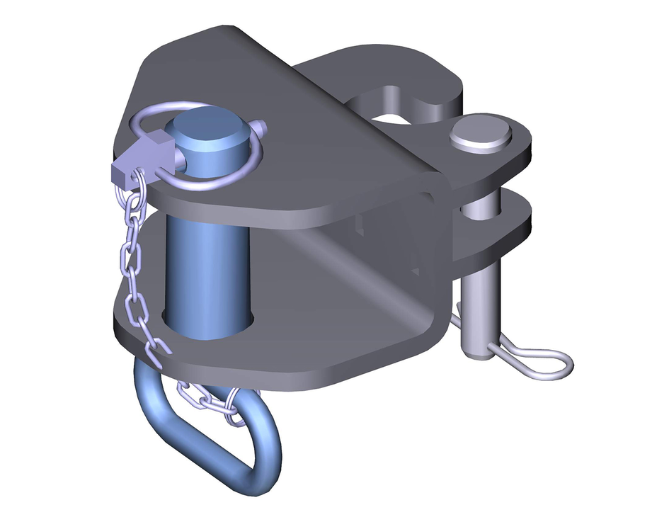
The front towing device is attached to the left frame and secured by a retaining pin.
Definition of the term, hydraulic PTO
Power Take Off = hydraulic force output
Definition of the term, AUX
Auxiliary valve
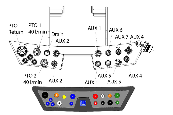
Fit a dust cap to an unused connection to provide protection.
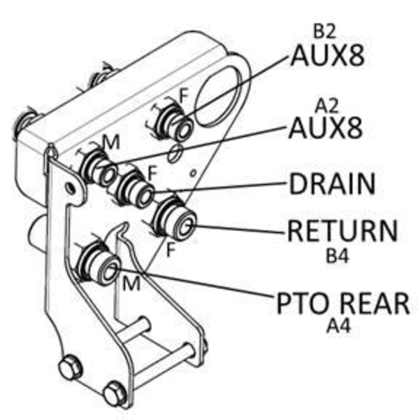
Fit a dust cap to an unused connection to provide protection.
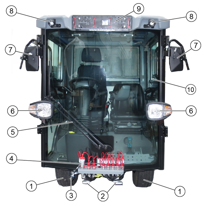
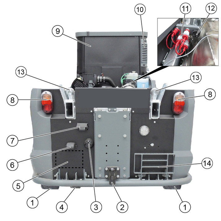
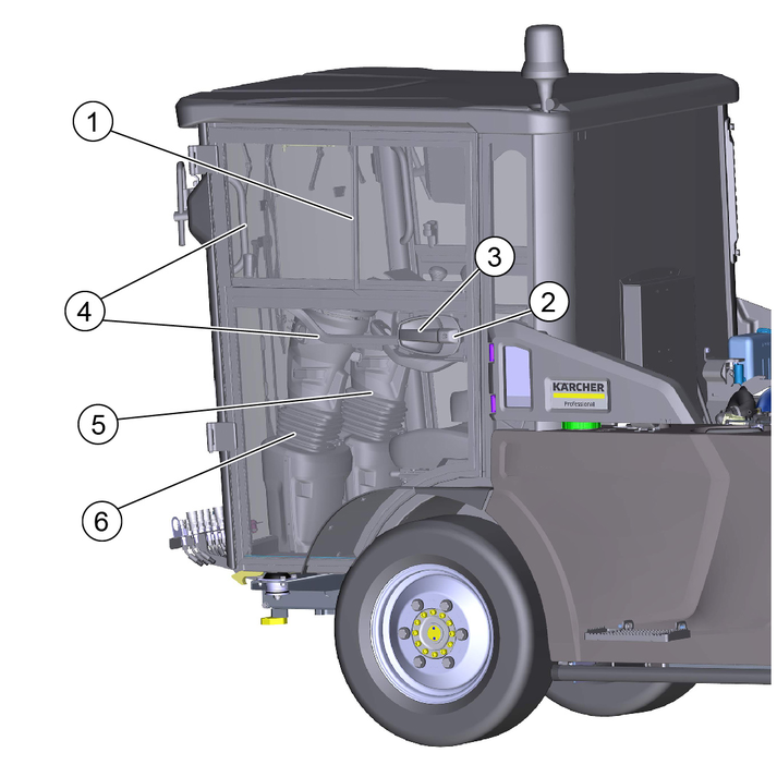
For various maintenance or cleaning work, the corresponding panels must be opened. The description of the maintenance and cleaning work can be found in the “Care and maintenance” chapter.
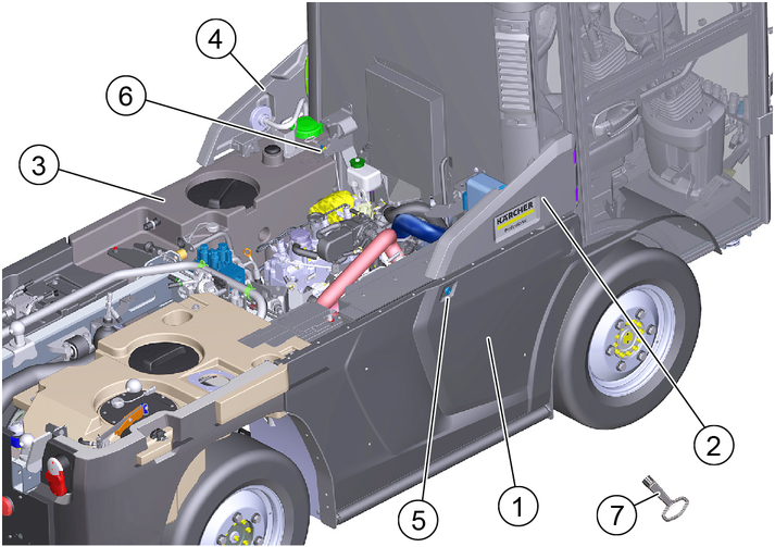
Figure: Shown without cover
Radiator grille: Unlock with square wrench and swing outwards.
Cleaning the combination cooler
Cleaning the air-conditioner condenser
Right-hand service flap: Swing out to open.
Refilling with DEF or AdBlue®
Checking / filling the wiping water
Checking / topping up the expansion tank coolant
Bonnet/fresh water tank: Unlock with a square wrench and swing outwards.
Checking the engine oil level
Emergency release of the parking brake
Check the brake fluid filling level
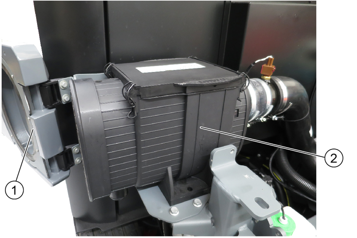
Left-hand service flap: Swing out to open.
Cleaning the air intake on the side of the air filter housing
Opening the air filter cover from above and cleaning the air filter
Square wrench: For unlocking the radiator grille and bonnet/water tank
Close both doors after parking the vehicle.
The driver's doors each serve as an emergency exit.
Right-hand steering variant
The driver's seat and the driver's door are located to the right in the direction of travel, a second door is located on the left side of the driver cabin.
Left-hand steering variant
The driver's seat and the driver's door are located to the left in the direction of travel, a second door is located on the right side of the driver cabin.
Entry and exit aid
Handles that can be used as entry and exit aids are located inside the doors and on the A-pillar.
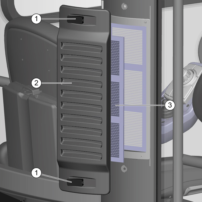
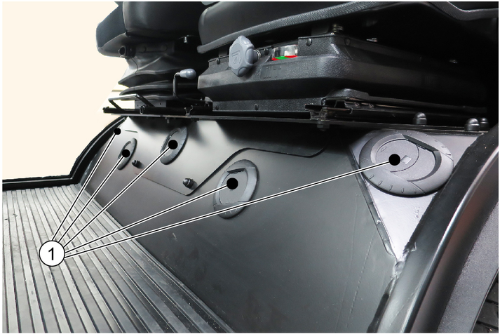
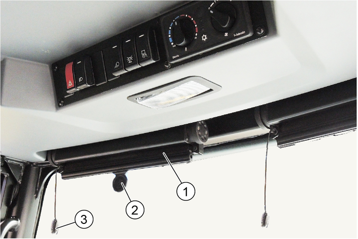
The fresh air is drawn in through a fine dust filter at the driver cabin (rear right).
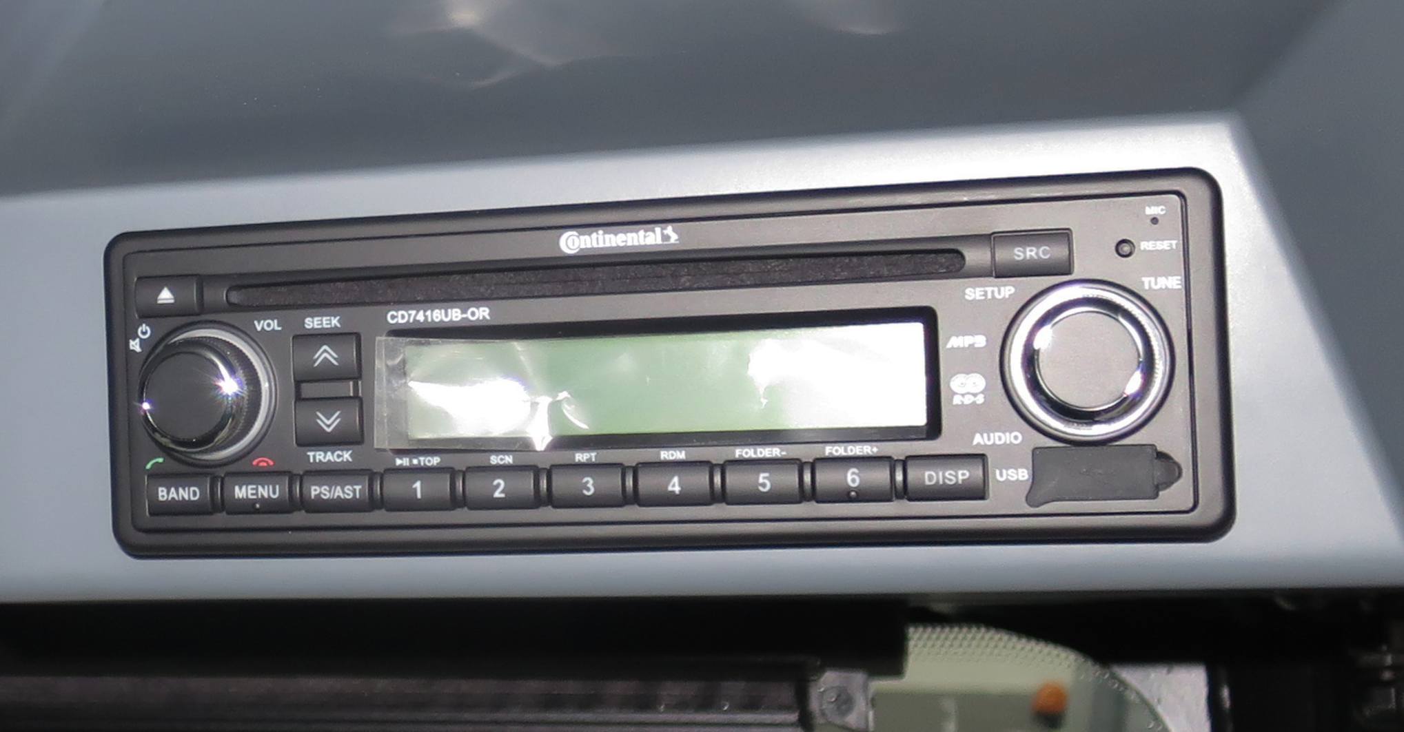
The optionally available radio is locate in the ceiling console.
See the manufacturer's operating instructions for operating the radio.
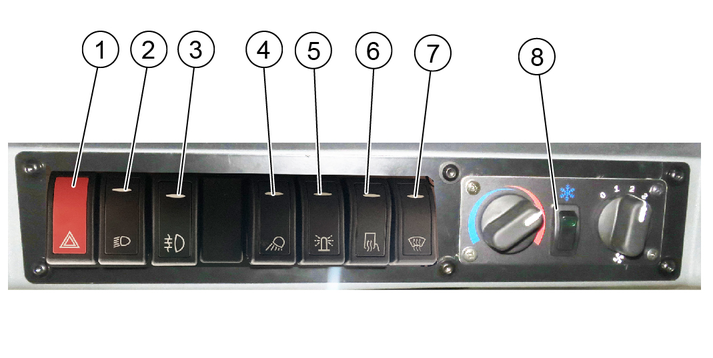
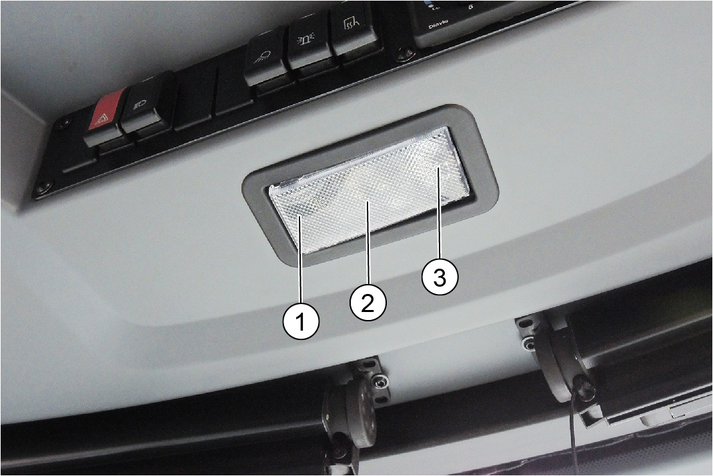
The switch panel is located in the ceiling console.
The indicator in the switch lights up when it is switched on.
The control elements are located in the ceiling console.
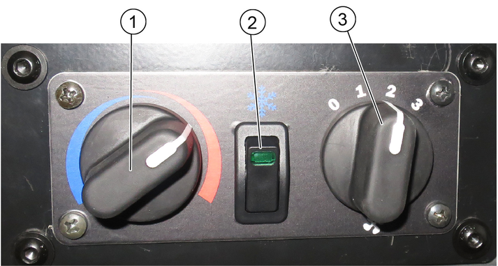
The air-conditioner will not be activated until the blower motor speed controller is at least at level 1.
Make sure you have a comfortable climate while in the driver cabin. Adjust this using the control elements.
Adjust the ventilation nozzles draft-free. Press the ventilation flap to open / close. Turn the ventilation flap to change the direction of the airflow.
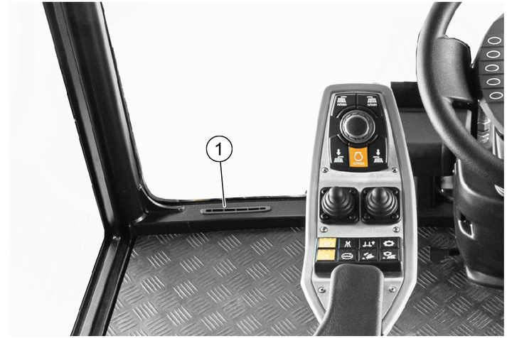
Keep the air duct free in the footwell in front of the windscreen. Otherwise it will fog up.
The control elements are located in the ceiling console.
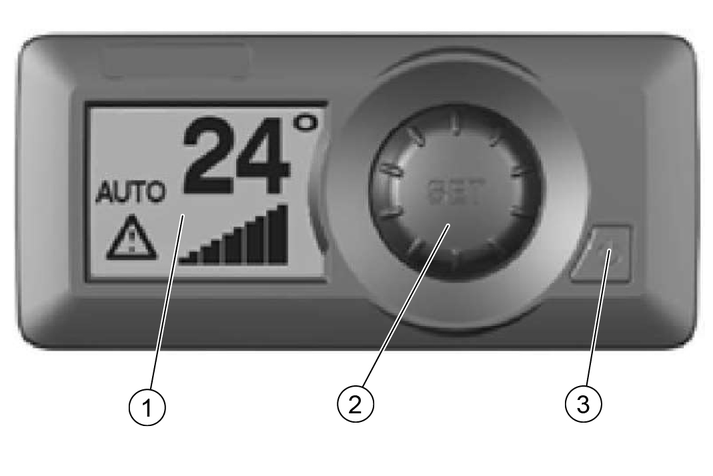
After switching on, the LCD display shows the selected temperature, the fan speed and the selected setting.
In the test/diagnostic mode, it displays appropriate messages for troubleshooting.
The settings can be selected using the adjustment button. To do this, switch on the air-conditioner.
Press the adjustment button (SET).
Turn the adjustment button clockwise or counterclockwise to select the desired settings.
The system automatically returns to the main display after a few seconds with the selected settings. Do not press the adjustment button.

To set the contrast and brightness of the display, as well as the temperature display in °C or °F, press the adjustment button twice with the air-conditioner switched on. Make the required settings by turning it clockwise or counterclockwise. Press the adjustment button once to save. Wait a few seconds, the system will automatically return to the main display.
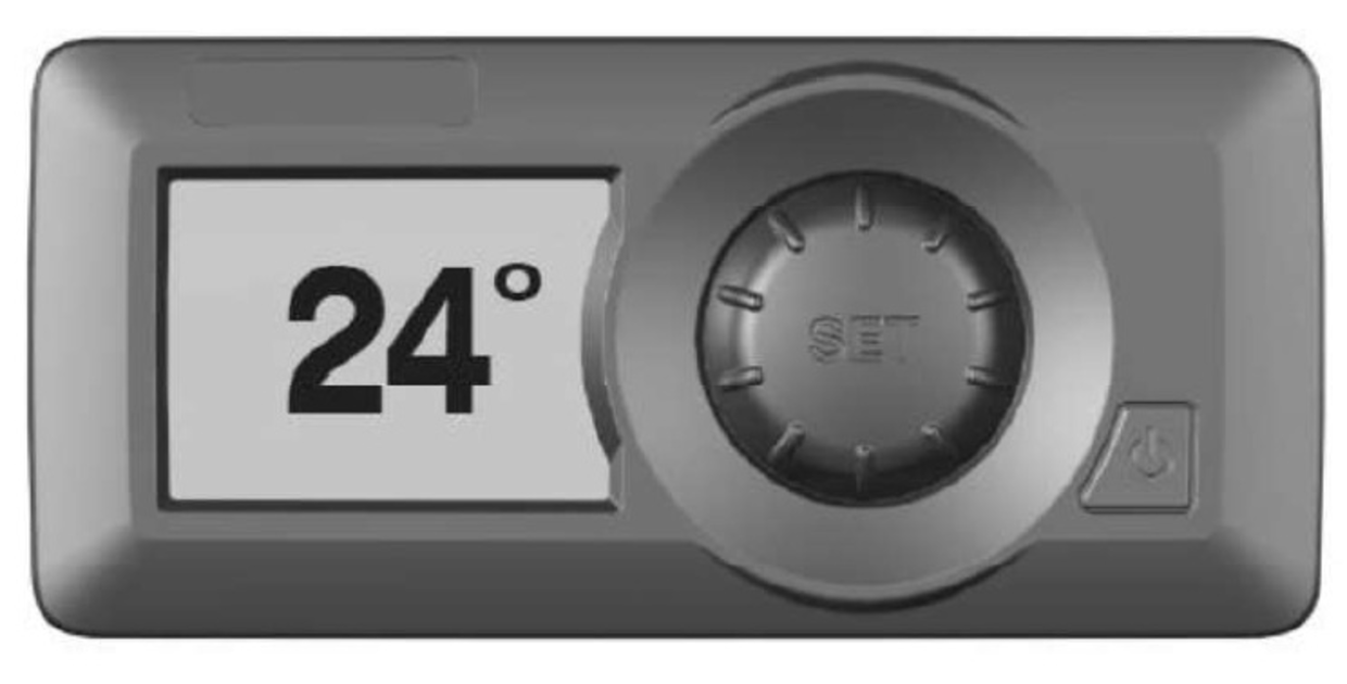
When the air-conditioner is turned off, the backlight turns off and the preset setting is displayed.
The air-conditioner also has menus for setup, fault displays or statistics. This is reserved for the authorized Customer Service. If you have any questions or in the event of a fault, please contact the authorized Customer Service.
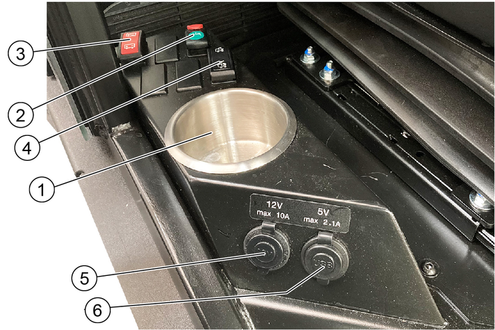
A console with switches, a storage container for various small parts and sockets for USB and 12V is located next to the driver's seat.
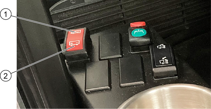
All functions used for the vehicle can be deactivated with the battery disconnector relay switch.
Disconnect the battery each time the vehicle is parked by pressing the switch to the "Disconnect battery" position. Please wait at least 60 seconds after switching off the combustion engine before operating the switch.
Note: After the combustion engine has been switched off, the control units are gradually deactivated. The battery can only be disconnected after the last device has shut down. Therefore, observe the waiting time of 60 seconds.
To start up, activate the battery by pressing the switch in the "Activate battery" position.
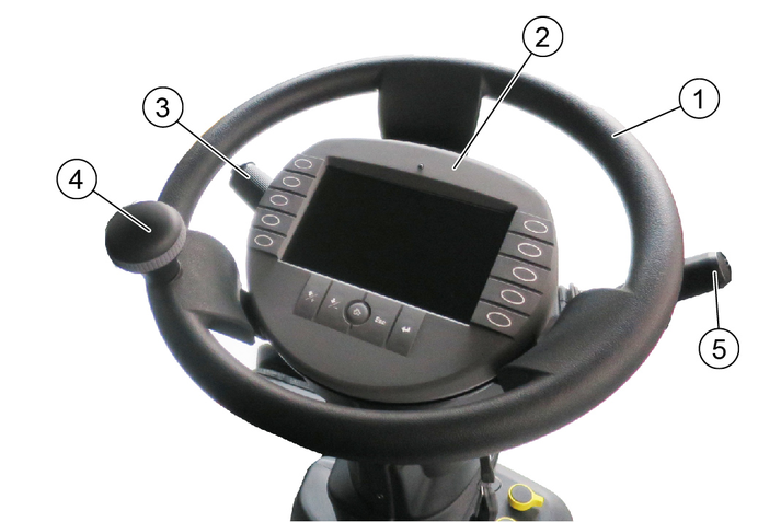
Horns: Press the button on the end
Flash to the right: Lever forwards
Flash to the left: Lever backwards
High beam: Press the lever down with the driving light switched on
Flasher: Pull lever and release
Windscreen wiper interval: Turn the ring forward
The period of the wiper interval is adjustable (programmable).
To do this, turn the ring to "Intermittent wiping", wait for the desired time interval then switch it off and switch it on again within 1.5 seconds. The set time interval returns to its basic programming after switching off the ignition.
Continuous wiping: Turn the ring backwards
1st level for normal wiping speed
2nd level by turning further for fast wiping speed
Wiping water: Press the ring
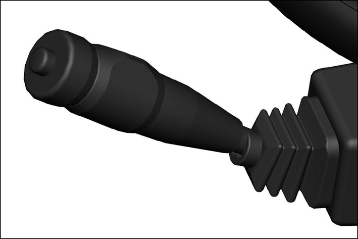
The travel direction is selected using the travel direction selector switch.
Operating error
The vehicle must be at a standstill and the travel direction selector switch in the neutral position in order to select the travel direction.
If the direction switch is in the forward or reverse direction when selecting the travel direction, the symbol display will change but the switchover will not occur.
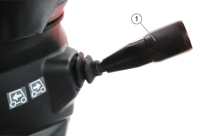
Pull the selector switch upwards towards the steering wheel, then move it in the desired direction of travel (front / rear).
The travel direction is shown in the display.
Bring the travel direction selector switch into the middle position (neutral position).
The driving engine idles.
Select the desired transport speed or working speed using the accelerator pedal.
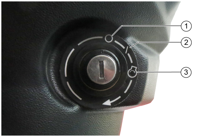
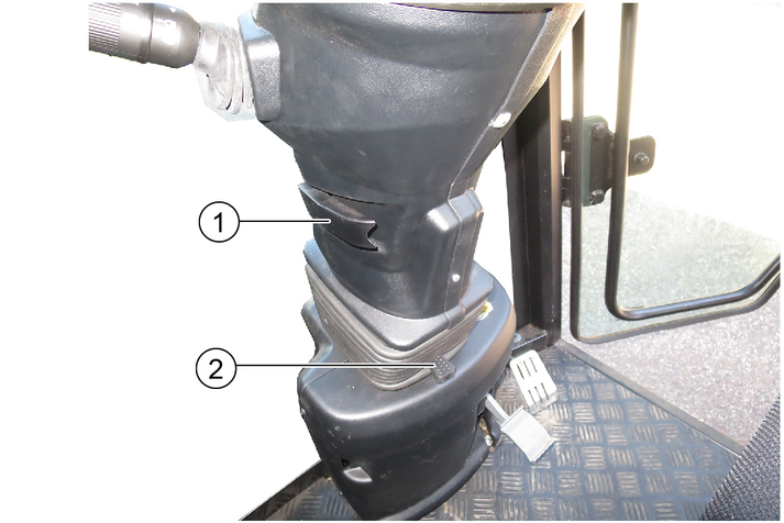
The ignition lock is located below the travel direction selector switch.
Releasing the accelerator pedal provides no noticeable braking effect in transport mode.
The brake pedal must be pressed in order to brake.
Transport mode: Pressing the accelerator pedal increases the engine speed and the driving speed.
Releasing the accelerator pedal reduces the engine speed and the driving speed.
Working mode: The engine speed is set to a fixed value. Regulate the desired working speed using the accelerator pedal.
Only the working speed and not the engine speed decreases when the accelerator pedal is released.
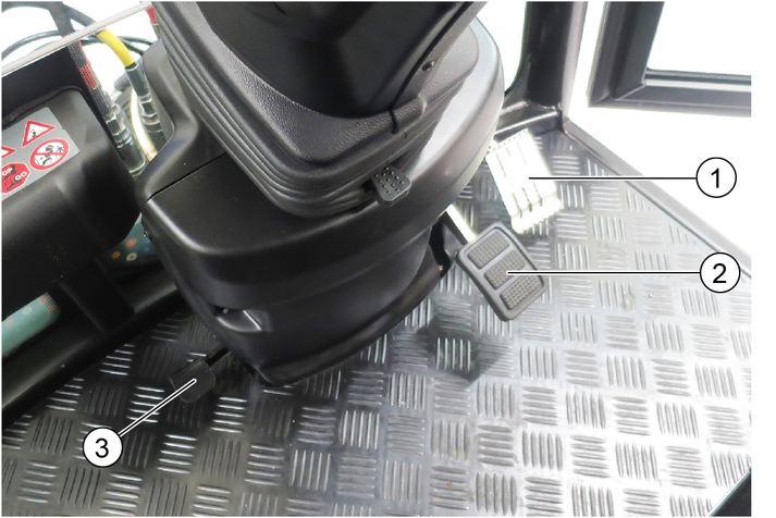
The brake pedal activates the front and rear wheel braking system.
The brake pedal must be pressed in order to brake.
Releasing the accelerator pedal provides no noticeable braking effect.
The parking brake requires hydraulic pressure to release. The brakes are automatically actuated when the engine is switched off.
The parking brake is also applied when the engine is running and the travel direction lever is in the NEUTRAL position.
The "Parking brake applied" warning light in the multifunction display lights up when the parking brake is applied.
The following indicators are shown on the display after switching on the ignition.
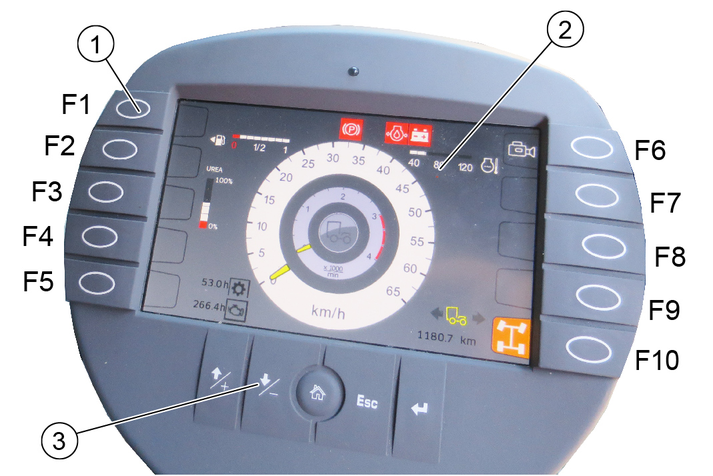
Pressing the corresponding function key changes the display. Return by pressing again or by pressing the "Home" button.
The settings are changed using the settings buttons.
Assignment of the function keys | |
|---|---|
F1 | Information such as the vehicle operating instructions can be provided here In working mode: Switch on high-pressure cleaner (option) |
F2 | Display the date and time |
F3 | Settings |
F4 | In working mode: Bridging the seat contact switch |
F5 | Reversing warning buzzer on/off |
F6 | Reversing camera on/off |
F7 | Suction-mouth camera (optional with sweeping attachment kit) |
F8 | Set Tempomat |
F9 | Resume Tempomat |
F10 | Choice of 2 or 4-wheel steering |
Setting buttons | ||
|---|---|---|
 | + button | Jumps one field up when making settings |
 | - button | Jumps one field down when making settings |
 | "Home" button | Navigates to the "Home" screen for the respective operating mode (Transport / Work) |
 | Esc button | Jumps one step back when making settings |
 | "Return" button | Completes a setting procedure |
The following values are shown on the display in Start/Transport mode.
Forwards direction of travel
Neutral position
Travel direction backwards
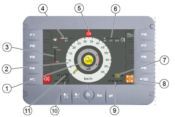
The following indicators are shown on the display when switching to Working mode (PTO).
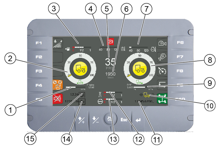
Yellow pointer: PTO on the left
Grey pointer: PTO on the right
Transport mode and 2-wheel steering are automatically selected when starting the engine.
In working mode (PTO on), the 4-wheel steering can be selected.
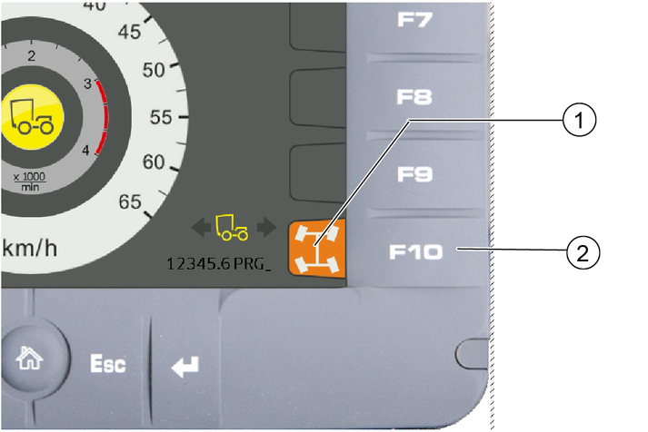
Press function key F10.
Turn the steering wheel over the centre position (reference point). If the display turns green, the steering mode is activated.
The reversing camera is located at the rear of the vehicle.
When reversing, the camera automatically turns on and appears in the display.
The reversing camera is no substitute for an awareness of the surroundings
Always pay attention to the surroundings when reversing.
Ensure no persons, animals or objects are located in the manoeuvring range.
Is required when performing work where the driver must leave the driver's seat, e.g. with the manual suction hose (option) or high-pressure cleaner (option).
Travel direction selector switch to the NEUTRAL position.
Activate the hydraulic system (PTO on).
Press function key F4 on the display.
The "Seat contact switch overridden" warning symbol appears on the display.
The seat contact switch is now bridged and the PTO remains active.
Green indicator lights are indications.
Orange indicator lights are indications of errors or pending switchovers of operating states:
It is possible to continue driving with appropriate caution.
Seek the help of a specialist.
Red indicator lights are errors and safety-related warnings.
Read the operating instructions!
Do not drive further!
Seek the help of a specialist.
The following indicator lights can be shown on the display.
 | Parking light |
 | Driving light |
 | High beam |
 | Driving direction indicator |
 | Trailer indicator light |
 | Crossroads function active |
 | AUX X floating function active |
 | AUX Y floating function active |
 | AUX X and Y floating function active |
 | Function 99 dB(A) active |
 | Reversing camera active |
 | 2-wheel steering activated |
 | 2-wheel steering ready for selection |
 | 4-wheel steering activated |
 | 4-wheel steering ready for selection |
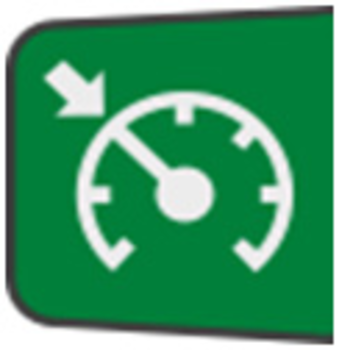 | Cruise control activated |
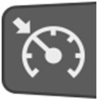 | Cruise control inactive |
 | Cruise control (Resume) Activate the previously set speed |
 | Neutral position (middle position) of the travel direction selector switch required |
 | Steering error |
 | Seat contact switch not recognized |
 | Seat contact overwritten manually (bridged) |
 | Service required |
 | Preheating active |
 | General fault (uncritical), check fault list |
 | Fuel level warning |
 | Perform the regeneration process |
 | Engine malfunction (uncritical) |
 | Warning, engine must be switched off |
 | Warning, working hydraulics must be switched off |
 | Working hydraulics must be switched on |
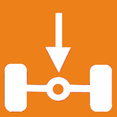 | Axle load warning |
 | Drive oil temperature warning |
 | High hydraulic oil level warning |
 | Reverse function active |
 | Fog lights on |
 | High exhaust temperature (regeneration is active) |
 | Regeneration is active (Inhibit) |
 | Vehicle performance is limited, speed is limited |
 | Warning, vehicle is in limited condition (transport mode) |
 | Warning, generator system is faulty |
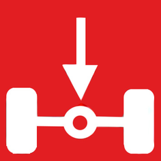 | Warning, axle load too high |
 | Drive oil temperature fault |
 | DCU fault (control unit) |
 | DCU in stop state |
 | Warning, reversing not allowed |
 | Low hydraulic oil level warning |
 | Hydraulic oil filter malfunction |
 | Warning, hydraulic oil temperature high |
 | Seat contact switch malfunction |
 | Engine air filter malfunction |
 | Critical malfunction, switch off the engine |
 | Warning, engine coolant temperature too high |
 | Parking brake active |
 | Reversing signal off |
 | Warning, brake pressure too low |
 | Warning, engine oil pressure too low |
 | Switch off the engine |
 | Engine fault warning
|
 | Water from the engine in the fuel |
 | Engine fault in the exhaust treatment system |
 | Warning, hydraulic circuits are automatically vented (only when starting up for the first time) |
 | Warning, hydraulic controller offline |
 | Warning, display offline |
 | Warning, speed is too high - reduce speed |
 | Warning, service brake faulty |
 | Warning, parking brake faulty |
 | Brake fluid warning |
 | Warning, engine temperature high |
The control panel is located on the arm rest next to the driver's seat. The arm rest can be individually adjusted to suit the driver, see chapter "Setting the driver's seat".
The indicators in the switches light when the switches are switched on.
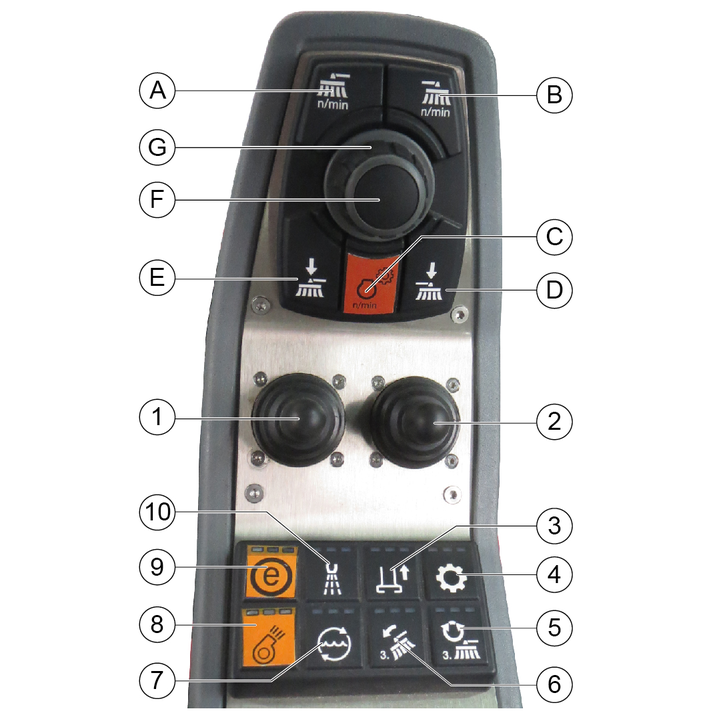
(A) | Front PTO, 40 l/min maximum The hydraulic power can be adjusted via a potentiometer |
(B) | Front PTO, 40 l/min maximum The hydraulic power can be adjusted via a potentiometer |
(C) | Button for setting the engine speed NoteThe speed can be adjusted in steps of 100 rpm. |
(D) | Not used |
(E) | Rear PTO, 60 l/min maximum |
(F) | Press the button to save set values or programs and open submenus. |
(G) | Rotary knob for changing values and selecting programs. |
The default display language is English, but the language can be changed via the Settings menu.
The display can be used for e.g. making vehicle settings, making settings for the display and displaying vehicle information.
In detail, these are the following functions described below.
Display settings
System information
DPF (information on regeneration)
This area is reserved for customer service
Pressure relief of the hydraulic system
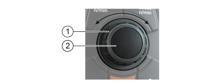
The central elements for navigating and selecting the menu items in the display are the rotary knob and button.
Pressing the button opens submenus and saves selected settings.
The menu items can be selected using the rotary knob.
 |
|
 |
|
 |
|
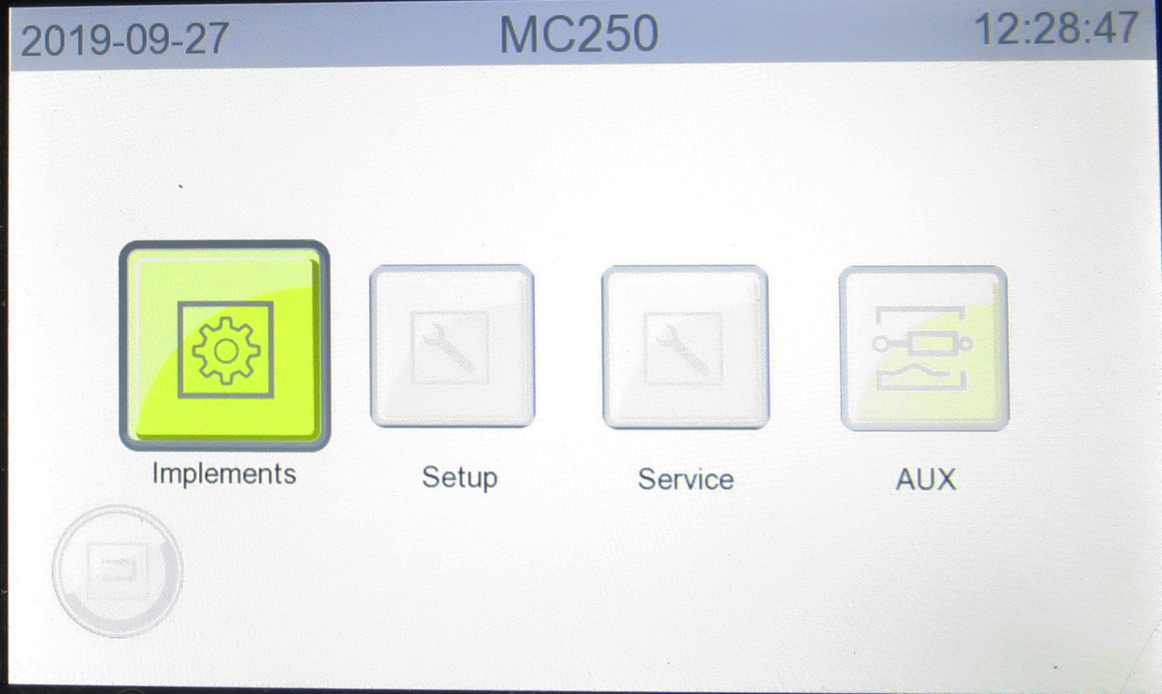
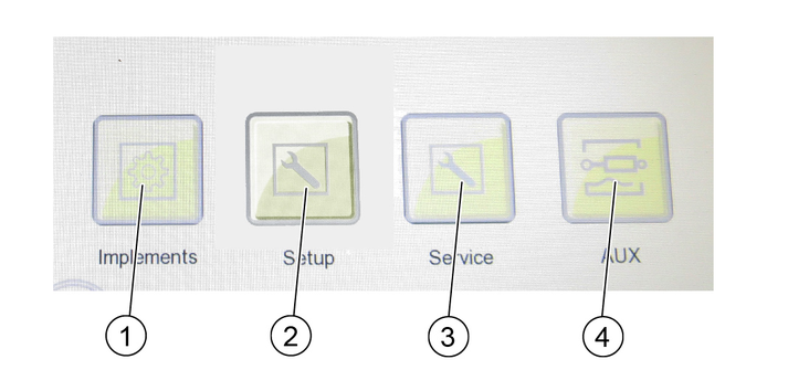
Figure: Attachments menu selection
If attachments are attached to the vehicle, they must be configured in the menu. The following configurations, among others, can be selected:
Device carrier
Sweeper
Winter service
Wet cleaning
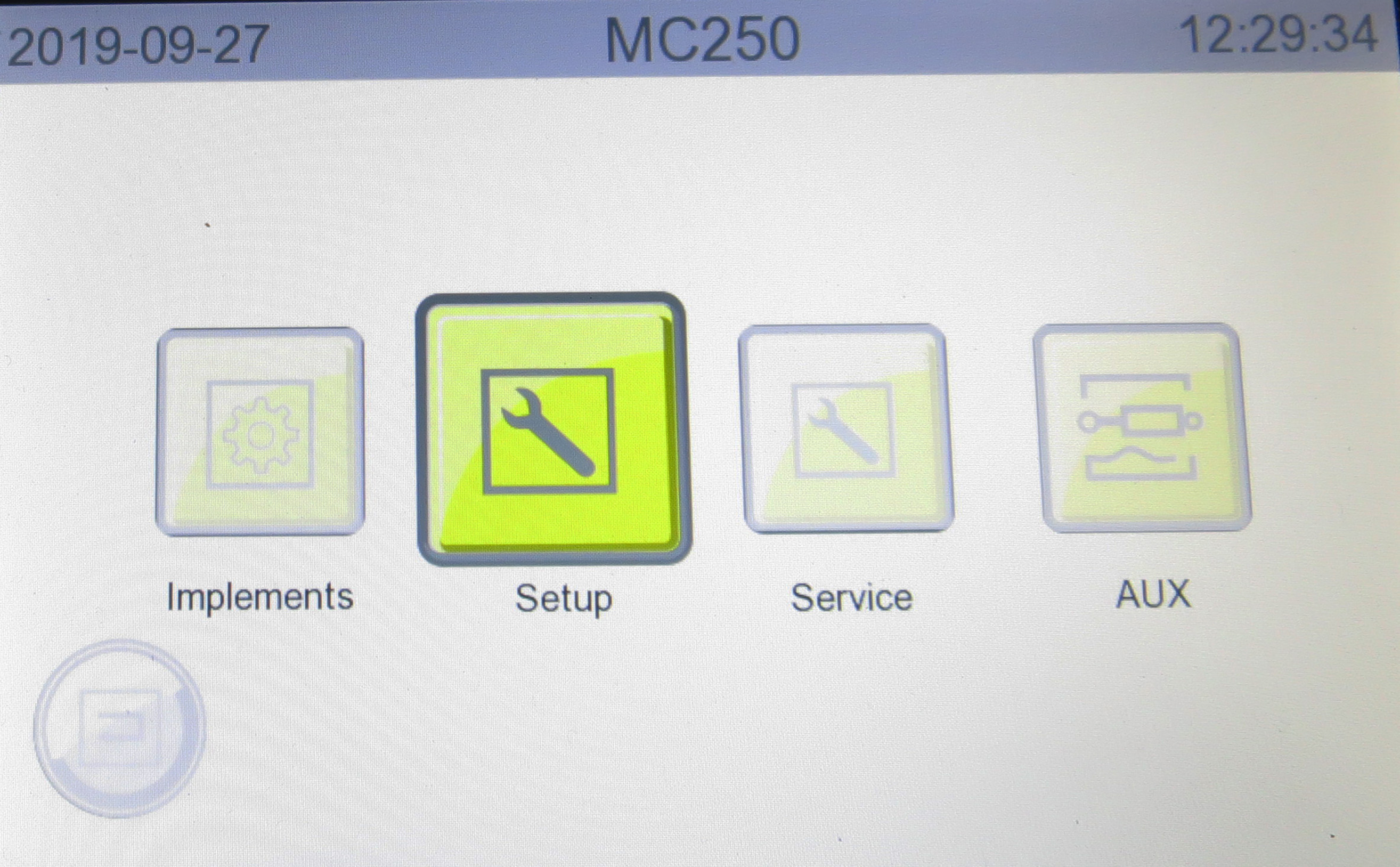
Figure: Settings menu selection
The Settings menu contains the following submenus.
Service
This menu item is reserved for authorise customer service personnel
Settings
Display brightness and contrast
Speed units (km/h / mph) and temperature units (°C / °F)
Language
Date and time
Infos
Display of vehicle-specific system information
DPF (Diesel particle filter)
Indicator shown when the next automatic regeneration will start
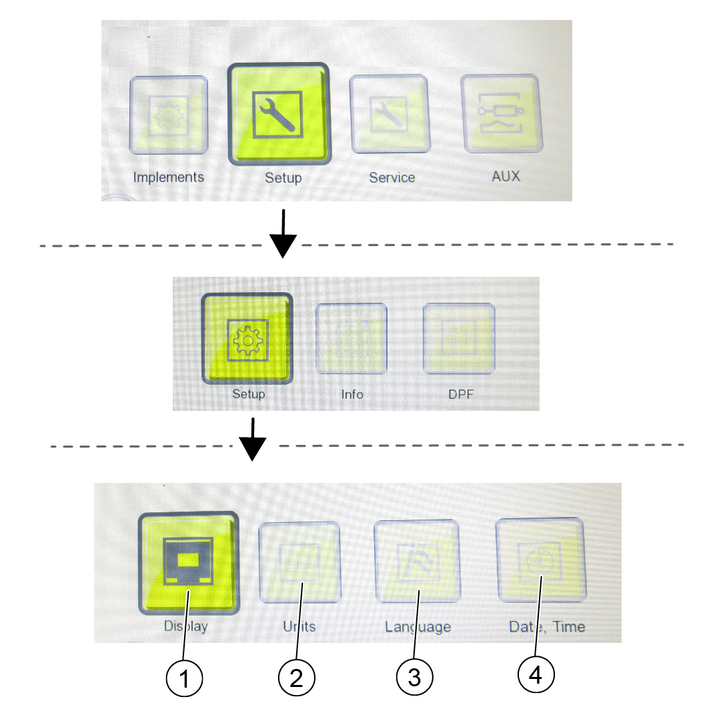
Press the "Settings" button until reaching the display settings level.
Use the "Display", "Units", "Language" and "Date, Time" buttons to open the submenus and make the desired settings.
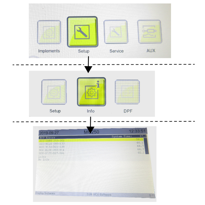
Use the "Settings" and "Infos" buttons to access the system information window.
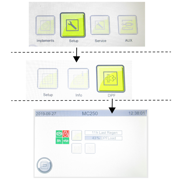
Use the "Settings" and "DPF" buttons to access the DPF window.
See chapter for further information Regeneration process for vehicles with a diesel particle filter (DPF).
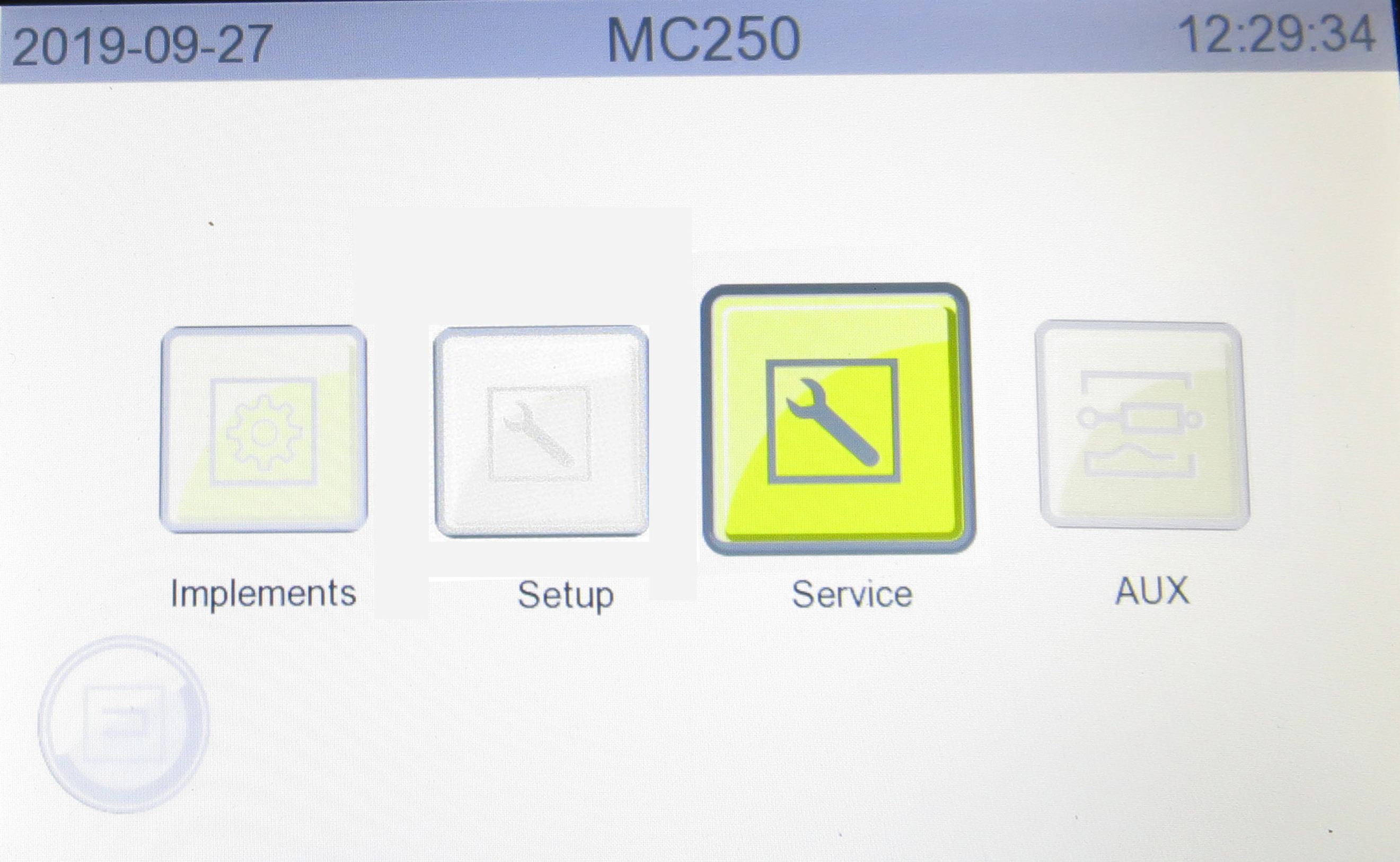
Figure: Service menu selection
This menu is reserved for the authorized Customer Service.
The hydraulic system must be depressurised before disconnecting the hydraulic hoses from the hydraulic connections.
Risk of injury, risk of damage
Lower lifted attachments before depressurizing.
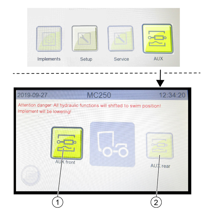
Select the menu items with the button and rotary ring on the control panel. Confirm the selected setting with the button.
Switch to the next level by pressing the "AUX" button.
Select AUX pressure relief front or rear.
Read the operating instructions for attachments!
When using attachments or pulled devices and trailers prior to initial startup, read the corresponding operating instructions and follow them.
Pay attention to permissible loads, see chapter (→).
Risk of accident and injury due to faulty vehicle
Do not start up the vehicle if one point from the safety check is not fulfilled but rather repair the vehicle.
Perform the recommended safety checks each time before using the vehicle.
Check the following points before each startup:
If the battery disconnector relay switch is set to "Battery activated". See chapter Battery disconnector relay switch
Check the cleanliness of the hydraulic connections
Check the hydraulic lines for leakage and damage
Check the hydraulic oil level, see chapter Checking the hydraulic oil level and topping up the hydraulic oil
Check the engine oil level, see chapter Checking/topping up the engine oil level
Check the coolant level, see chapter Checking the coolant level and topping up the coolant
Check the brake fluid level, see chapter Checking the brake fluid level in the reservoir
Check the coolant for sufficient antifreeze if a danger of frost exists
Check the electrical cables for damage
Check that all nuts and bolts are securely seated
Check the vehicle, engine and radiator grille for damage
Check the cleanliness of the engine air filter
Check the cleanliness of the cab dust filter
Check the fluid level in the windscreen washer reservoir, see chapter Filling the wiping water container
Type pressures and tyre wear
Check that the lighting and flashing system function
Ease of movement of the accelerator pedal
Are the temperature indicator and fuel level indicator functioning?
Danger of accident
Only adjust the driver’s seat when the vehicle is stationary.
Risk of damage
Do not use the folded backrest as a storage area when driving on public roads or secure accordingly
Only the seats listed below and offered by Kärcher may be used. Otherwise the vibration values cannot be guaranteed.
The driver's seat is automatically damped.
If there is no passenger seat, there is a directly accessible storage compartment
Kärcher offers 3 variants of driver's seats:
Seat König K210MVGL-P350-W2
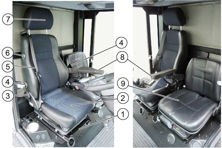
Seat Cobo SC47M-M200 (shown without arm rest)
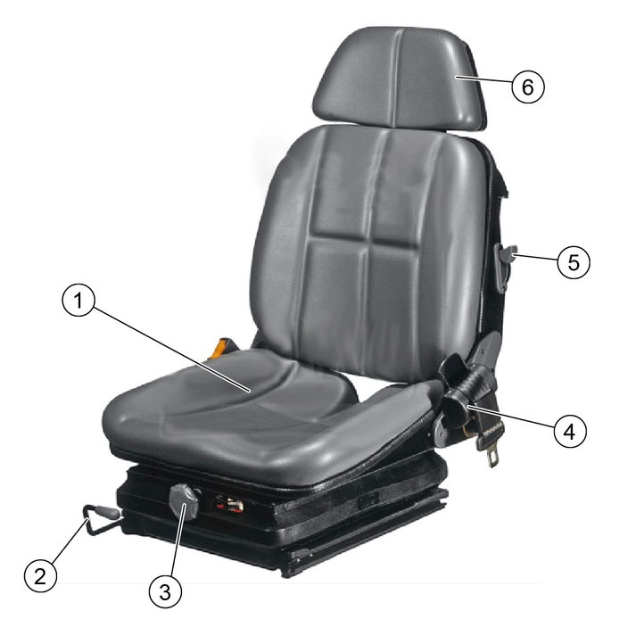
Seat Grammer MSG75GL / 522 (shown without arm rest)
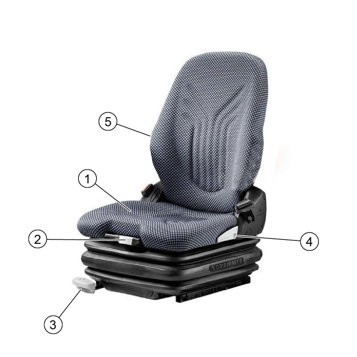
Adjust the inclination, height and position of the left arm rest for operating the control panel.
Adjust the driver's seat so that the pedals and steering wheel can be operated safely. The Grammer and König driver's seats have a lumbar support (lumbar support).
The height of the air-sprung driver's seat (Grammer and King) can still be adjusted, bring the seat into the highest possible position using the compressor, then release air with the spring until the seat has dropped 2-3 cm.
The passenger seat backrest and seat are hinged. Under the seat there is a storage compartment that can be used for storing vehicle documents and miscellaneous small items.
Danger of accident
Only adjust the position of the steering wheel when the device is standing.
Pull and hold the inclination adjustment lever and set the steering wheel to the desired inclination.
Push in the lever.
Release the height adjustment locking lever and set the steering wheel to the desired height.
Lock the locking lever.
Risk of explosion
Do not refuel in confined spaces.
Do not smoke and avoid open flames.
Ensure that no fuel gets on hot surfaces.
Risk of injury
Note the risk of slipping due to spilt fuel.
Fuel expands when heated, do not fill up to the brim.
Switch off the ignition.
Open the tank cap.
Fill with fuel.
Only diesel fuel according to DIN EN 590 may be used.
Wipe of any spilt fuel and close the tank cap.
DEF (Diesel Exhaust Fluid) is manufactured in compliance with strict quality standards. Only use a fluid that complies with ISO 22241 standards.
It is prohibited to use urea solutions whose properties differ from those specified.
Where possible, do not partially fill the tank with partial quantities otherwise a warning light is displayed. If this warning light comes on you cannot reset it, but it goes out after several refuelling operations. This does not affect the functionality.
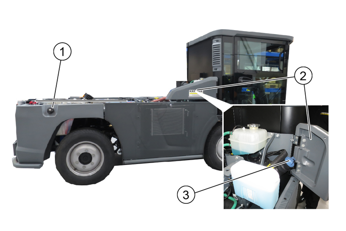
Only refuel when the filling level of the DEF container is well below 50% (shown in the display).
Open the right-hand service flap.
Open the blue DEF reservoir cap.
Add DEF, do not overfill.
Rinse off excess DEF with plenty of water.
Close the reservoir cap and right-hand service flap.
Risk of crushing
Make sure that there no persons are in the vicinity of the vehicle during operation.
When using the vehicle as a tractor, make sure that there are no persons between the vehicle and the trailer during operation.
Risk of burns
Only use the vehicle if all panels are attached.
Risk of damage due to overheated hydraulic oil or overheated engine
If the hydraulic oil temperature is too high or the coolant temperature is too high, run the engine at idling speed until the temperature drops below the "warning lamp off" trigger value.
Risk of damage due to lack of lubrication
If the "Engine oil pressure" warning light comes on during operation, immediately move the vehicle out of the hazard zone of the flowing traffic and switch off the engine. Then have the fault fixed.
Reduced stability due to attachments
Adjust the driving style.
Drive the first 100 hours of operation gently and avoid overloading.
After 50 operating hours: Initial inspection must be carried out by the authorized Customer Service according to the inspection checklist (ICL).
After 10 operating hours: Check the wheel bolts.
The parking brake requires hydraulic pressure to release. The brakes are automatically actuated when the engine is switched off.
The parking brake is also applied when the engine is running and the travel direction lever is in the NEUTRAL position.
The "Parking brake applied" warning light in the multifunction display lights up when the parking brake is applied.
Sit in the driver's seat.
Insert the ignition key in the ignition lock.
Bring the travel direction selector switch into the middle position (neutral position).
Switch on the ignition.
Wait until the display is complete.
Start the motor.
If the charge indicator and engine oil pressure warning lights do not go out, switch off the engine and remedy the fault. See chapter "Error messages in symbol displays"
In the event of ambient temperatures below 0 °C: Warm up the vehicle at low engine speed.
For a more detailed description of the travel direction selector switch, see the chapter "Steering wheel console | Travel direction selector switch"
Pull the selector switch upwards towards the steering wheel, then move it in the desired direction of travel (front / rear).
The travel direction is shown in the display.
Select the desired transport speed or working speed using the accelerator pedal.
Danger of accident
Only drive with the attachment properly mounted.
Risk of damage
Make sure that the vehicle does not become stuck when driving over obstacles.
Drive over obstacles up to 150 mm slowly and carefully at an angle of 45°.
Obstacles above 150 mm may only be driven over using a suitable ramp.
Risk of damage due to flashing beacon
Pay attention to the protruding flashing beacon (2.20 m) when driving into underground garages etc. If necessary, remove it beforehand. Do not stand on the bonnet (fresh water tank).
Danger of accident
Switch off the PTO when driving on public roads for transportation purposes (not when cleaning public roads).
Releasing the accelerator pedal provides no noticeable braking effect.
Fasten the seat belt.
Carefully press the accelerator pedal.
Steer the travel direction using the steering wheel.
The brake pedal must be pressed in order to brake.
Take your foot from the accelerator pedal.
Releasing the accelerator pedal provides no noticeable braking effect in transport mode.
To stop or in an emergency, press the brake pedal.
The Tempomat is only active in Working mode.
Activating Tempomat
Select the desired working speed using the accelerator.
Press function key F 8.
Tempomat is activated.
Deactivating Tempomat
Press the brake pedal or function key F 8.
Function key F 9 (Resume Tempomat) activates the previously set speed.
Risk of injury due to attachments
Fully lower any mounted attachments.
Stop the vehicle.
Bring the travel direction selector switch into the neutral position (middle position).
The parking brake is automatically actuated in this position.
Lower mounted attachments (not the sweeping system).
Allow the engine to run in idle mode for 1 to 2 minutes.
Switch off the ignition and remove the ignition key.
For a longer stop, press the battery disconnector relay button. See "Battery disconnector relay" chapter.
If the battery is to be disconnected, wait another 30 seconds for the engine control unit storage procedure to finish.
The DPF collects soot particles that are burned off by increasing the emission temperature when the filter is clogged (regeneration).
The regeneration process runs either automatically during working mode or driving mode but can also be started manually if required.
The higher the speed when driving, or the greater the load, the less frequent the need for manual regeneration.
Risk of burns
During the regeneration process, exhaust gases up to a temperature of 600°C may be omitted.
Do not start the regeneration process in combustible areas.
Risk of burns from hot exhaust gases
Keep people, animals and flammable objects away from the regeneration area.
Only interrupt the regeneration process in the case of an emergency.
Manual regeneration is not possible at less than 50 hours.
The average duration of the burning procedure during manual regeneration is approximately 20 minutes.
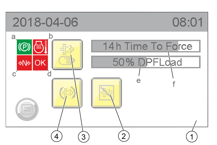
Manual regeneration can only be started when all 4 characteristics are green:
The parking brake is activated
The engine temperature has exceeded a particular limit value
The machine is in driving mode N (neutral)
OK then lights up green and the manual burning procedure can be started
Risk of burns
During the regeneration process, exhaust gases up to a temperature of 600°C may be omitted.
Do not start the regeneration process in combustible areas.
Work can continue during Automatic regeneration.
The automatic regeneration can be postponed in certain situations.
Check the frost protection of your vehicle. See chapter "Maintenance work | Check coolant level and top up with coolant ".
Please read the attachment operating instructions before fitting an attachment.
Attachments are optional and can be attached to the intended attachment points on the vehicle.
Danger due to changed vehicle centre of gravity and changed driving behaviour.
When transporting liquids and/or bulk material, such as e.g. loose chippings, swirling movements can occur which cause the vehicle to rock up and down.
In the case of conversions, especially when converting from winter to summer operation, and with changed loading conditions, the driver must adjust to a changed driving behaviour.
Danger of crushing when mounting attachments
Do not reach between attachment points and the attachment.
Risk of burns from hot hydraulic couplings
Wear protective gloves when disconnecting the hydraulic couplings.
Wear suitable protective clothing, safety gloves and gloves when installing and removing attachments. This also applies during usage and application.
Please contact your responsible dealer before fitting attachments that are not specifically intended for this vehicle. Your dealer will check if installation and use of these attachments is permitted on your vehicle. This is important for the safety of the driver and the vehicle and also for any warranty claims.
Attachments that endanger the safety or stability of the vehicle may not be used.
Risk of damage
Keep hydraulic connections clean.
Clean the plug and coupling with a lint-free cloth before use.
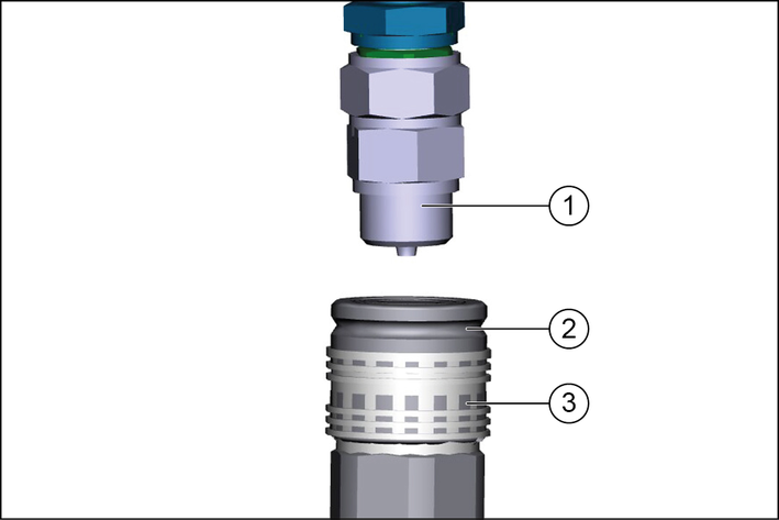
Pull the ring of the coupling sleeve downwards and hold.
Press the coupling connector of the attachment hydraulic hose into the coupling sleeve.
Release the coupling ring. Check that it is securely engaged.
To decouple, pull the ring downwards, hold it and pull out the hydraulic hose.
For permissible support load and trailer load, see chapter (→).
The front axle of the vehicle must always be loaded with at least 30% of the net weight of the vehicle, and the rear axle must always be loaded with at least 30% of the net weight of the vehicle.
Before purchasing the attachment, check that these requirements are met by weighing the vehicle-attachment combination.
The following data is required for determining the total weight, the axle loads, the tyre loading capacity and the required minimum ballast:
All weights in kg (weigh the vehicle if necessary)
All dimensions in meters (m)
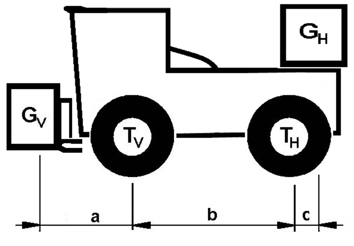
TL | (kg) | = | Net weight of the vehicle | * |
TV | (kg) | = | Front axle load of the empty vehicle | * |
TH | (kg) | = | Rear axle load of the empty vehicle | * |
GH | (kg) | = | Rear ballast total weight | ** |
GV | (kg) | = | Total weight of front attachment / front ballast | ** |
a | (m) | = | Distance between front attachment (front ballast) centre of gravity and middle of front axle, max. = 0.86 m | ** *** |
b | (m) | = | Wheelbase of the vehicle | * *** |
c | (m) | = | Distance between centre of rear axle and rear ballast centre of gravity | *** |
* See chapter "Technical data"
** See operating instructions of the attachment
*** Measure
See the manufacturer's specifications for the value "x" or use a value of x = 0.45 if no specifications are available.

Enter the result into the table.
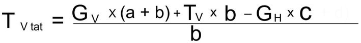
If the necessary minimum front ballast weight (GV min) is not reached with the front attachment (GV) then the weight of the front attachment must be increased to the minimum front ballast weight.
Enter the actual calculated permissible front axle load and the permissible front axle load specified in the machine operating instructions into the table.

If the necessary minimum rear ballast weight (GH min) is not reached with the rear attachment (GH), then the weight of the rear attachment must be increased to the minimum rear ballast weight.

Enter the result into the table.
Risk of injury due to incorrect transport
Mind the weight of the vehicle.
Slowly and carefully drive the vehicle onto the transport vehicle.
Damage to vehicle
Do not load the vehicle with the crane.
Do not use a forklift.
Slowly drive the vehicle onto the transport vehicle.
If the vehicle is not ready for running, see Chapter Towing the vehicle.
Danger of accident
Secure the vehicle against slipping during transport.
Park the vehicle and prevent it from rolling away, e.g. by activating the parking brake (travel direction selector switch to NEUTRAL - Middle position)
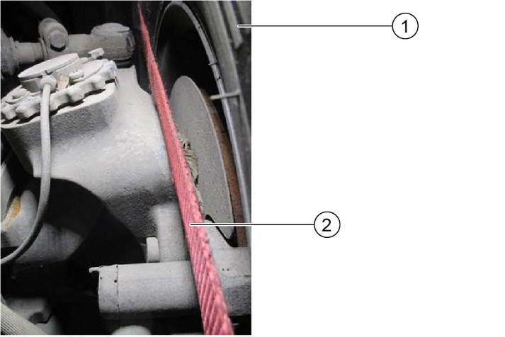
Secure the vehicle with a wheel retainer lashing system in accordance with valid guidelines.
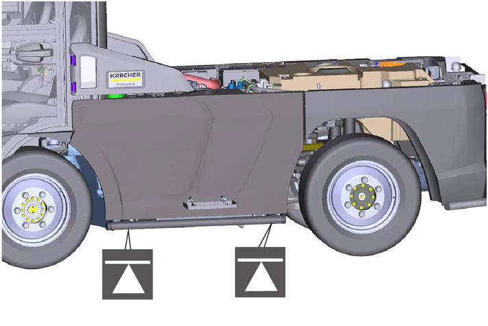
The transport is secured on the four tyres of the vehicle with the cross belts and the standard lashing straps.
Risk of damage
Place the straps on the wheel as close to the centre of the wheel as possible.
Do not touch or squeeze any cables.
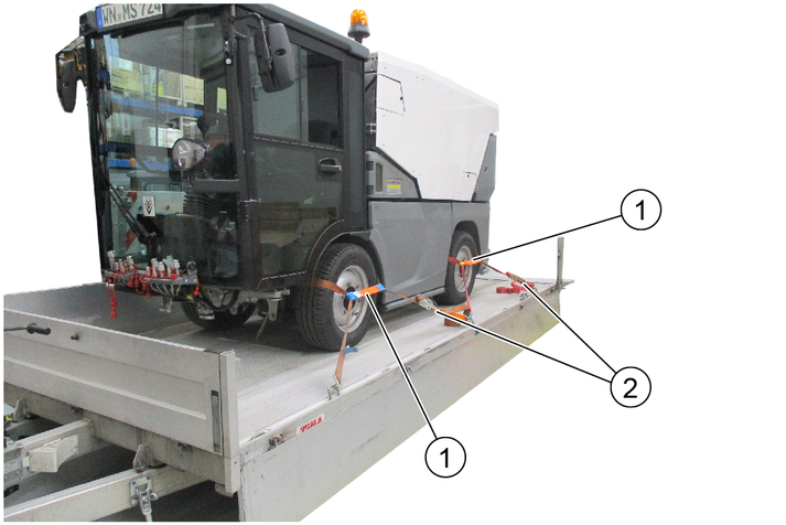
Secure the vehicle on the four wheels as shown.
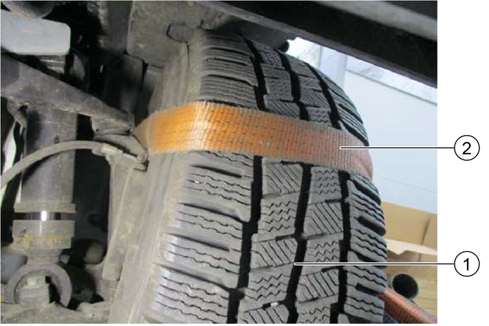
Lay the safety belt on the front wheel as shown.
Attach the cross belt to the standard safety belt on the outside of the wheel.
Lay the safety belt on the rear wheel as shown.
Attach a cross belt to the standard safety belt on the outside of the wheel.
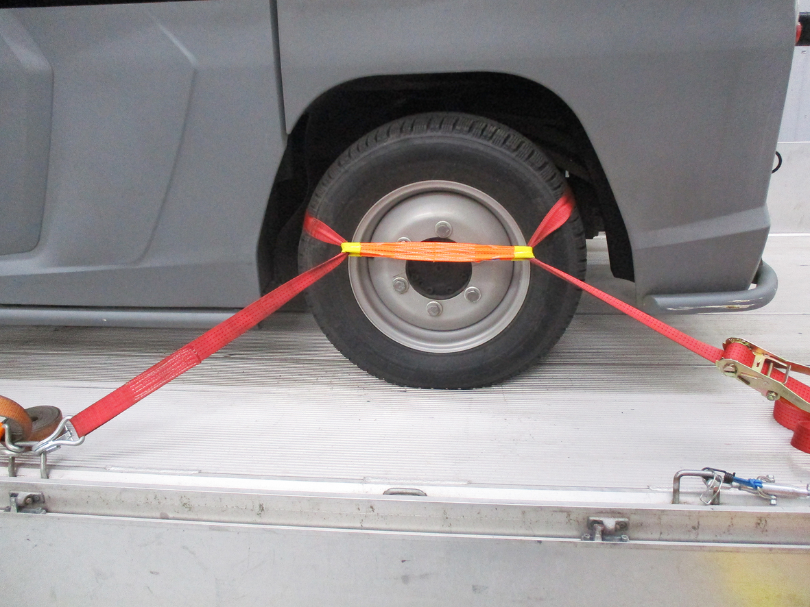
Hook the safety belts in the fastening eyelets and lash the vehicle down.
Before lashing it down, check that the belts are correctly positioned on the wheel.
Risk of damage due to incorrect towing
Only tow the vehicle at a walking pace and only until you are out of the hazard zone of flowing traffic. Then load the vehicle for transport.
Approach slowly and not jerkily.
Attach the tow rope or the tow bar to the towing device only.
Make sure the steering and the brake are working (only with the engine running).
In case of engine damage, release the parking brake for loading.
Do not tow the vehicle if the engine is defective, the steering or brake is faulty.
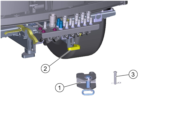
Attach the towing device to the mount. Secure with bolt and spring pin.
Attach the tow rope or tow bar to the towing device.
In the event of engine damage, release the parking brake for loading, see chapter "Releasing the parking brake".
Tow the vehicle out of the hazard zone and then load for transport.
Crush hazard
When working under raised attachments, ensure these are always mechanically locked (shimming).
Before you clean and service the vehicle, or exchange parts or adjust them to a different function, switch off the motor and remove the ignition key.
Check if your radio is secured with a radio code before disconnecting the battery.
Disconnect the battery before working on the electrical system.
Repairs may only be carried out by authorised customer service centres or by qualified staff in this area who are familiar with all relevant safety instructions.
Any welding work on the vehicle or attachments is only permitted by authorised Kärcher Customer Service.
Park the vehicle on a level surface.
Secure the vehicle against rolling away.
Switch off the ignition and remove the ignition key.
The service indicator lights up when appropriate maintenance must be performed according to the inspection checklist.
The service indicator flashes in the display:
For the first time after 50 operating hours, when the initial inspection must be carried out.
Thereafter according to the maintenance intervals according to the inspection checklist.
The service indicator must be reset by Customer Service.
To preserve eligibility for warranty claims, all servicing and maintenance work during the warranty period has to be performed by an authorised Customer Service (ICL), in accordance with the inspection check list.
Lubricate all bearings after washing the vehicle.
The intervals for testing and maintenance (daily / weekly) by the customer / operator are listed in the chapter "Vehicle maintenance plan".
Have the safety checks according to the applicable local regulations performed by the Customer Service department as necessary.
Further maintenance work must be carried out by the authorized Customer Service according to the inspection checklist. Please inform the Customer Service department in time.
To be performed by the operator / customer.

Assembly | Activity | Daily | Weekly |
|---|---|---|---|
Water cooler | Clean radiator fins | X | |
Oil cooler | Clean radiator fins | X | |
Coolant expansion reservoir | Check the coolant level | X | |
Check the water/antifreeze mixing ratio | Check seasonally or when changing the coolant | ||
V-belt | Check for tension and wear and tear | X | |
Hydraulic oil tank | Check the hydraulic oil level (shown on display) | X | |
Hydraulic couplings and connections | Check for leaks | X | |
Hydraulic hoses | Check for leakage and damage NoteExchange the hydraulic hoses according to the inspection checklist! | X | |
Battery poles | Check the battery poles for oxidation, brush off if necessary, and lubricate with terminal grease. Make sure the connection cables are firmly in place. | X | |
Check the engine oil level | Check | X | |
Brake fluid level | Check | X | |
Cab dust filter | Check | X | |
Tyres | Check the condition and filling pressure | X | |
Wiping water container | Check the filling level | X | |
Battery | Check | X | |
Exhaust system | Visual inspection | X | |
Lights | Check for correction function | X | |
Engine air filter | Check / clean or replace air filter. | X | |
Radiator grille | Cleaning | X | |
Air-conditioner | Check and clean the radiator fins | X | |
Parking brake | Check for correct function | X | |
Pedals | Check for correct function | X | |
Steering | Check for correct function | X | |
Warning sticker | Check the legibility, replace if necessary | X | |
Dust caps and covers for hydraulics | Check, replace if necessary | X | |
Screw connections | Check for tightness, tighten if necessary | X | |
Hoses and cable clamps | Check | X | |
Coolant hoses | Check | X | |
Fuel lines and connections | Check for leaks | X | |
Bowden cables and moving parts | Check for freedom of movement | X | |
Electrical cables | Check for damage | X | |
Bearings / lubrication points | Lubrication, see chapter "Vehicle lubrication plan" | X |
Lubrication point | Quantity | Interval |
|---|---|---|
Fresh water tank hinge, above | 1 | Weekly |
Fresh water tank hinge, below | 1 | Weekly |
Observe the manufacturer's specifications for wiping water fluid and antifreeze. Do not mix antifreeze with other antifreeze.

Open the right-hand service flap.
Open the cap on the wiping water container.
Fill with r water liquid.
If there is a risk of frost, add antifreeze according to manufacturer's instructions.
Close the cap on the wiping water container.
Risk of burns on account of hot components
Do not open or touch the radiator or parts of the cooling system while the motor is hot.
Risk of injury due to pressurised cooling system
Carefully open the expansion tank (2 levels).
Material damage due to incorrect coolant
Top up the coolant only when the engine is cold.
The water/antifreeze mixing ratio should be 60:40 to 50:50. This usually corresponds to frost protection from -25 °C to -40 °C.
The minimum mixing ratio should be 70:30 and the maximum mixing ratio 40:60. Further increasing the proportion of antifreeze (e.g. 30:70), does not further improve the freezing point.
The mixture of the coolant shall consist of deionised or distilled water and of radiator protection according to standards ASTM D 3306 Type 1 monoethylene glycol-based with addition of organic inhibitors.
For coolant, see chapter "Technical data".
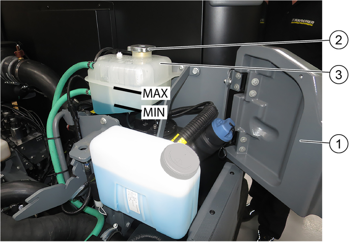
Check the filling level when the engine is cold.
Open the right-hand service flap.
Check the filling level in the expansion reservoir.
Note
The correct coolant level must be between MAX and MIN. In case of severe loss of coolant, carry out troubleshooting and correct any faults found.
Top up the coolant if necessary.
Add coolant
Turn the cap of the expansion tank to open and remove it.
Add approved coolant to expansion tank to top marking (MAX).
Fit the cap of the expansion tank and tighten.
Close the service flap.
Replace the air filter annually or every 1000 hours of operation
May only be replaced by customer service according to the inspection checklist (ICL)
May only be replaced by customer service according to the inspection checklist (ICL)
A hydraulic oil level that is too low is shown on the display.
Top up the hydraulic oil if necessary.
Note
Lacking hydraulic oil can be topped up using a special accessory tool connected to the leakage coupling on the vehicle. If required, request the order no. at Kärcher or have Kärcher Customer Service do the topping up.
For the hydraulic oil type: See chapter "Technical data".
Risk of injury
Observe the safety instructions on the handling of batteries.
Battery care
Check that the battery terminals and terminal clamps are protected with a sufficient quantity of terminal grease.
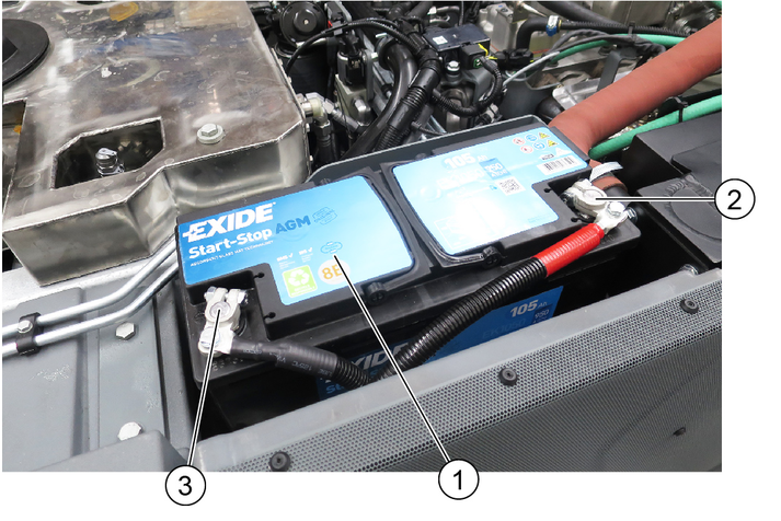
Installing the battery
Fit the battery into the battery holder.
Screw the bracket on the battery base tight.
Connect the terminal clamp (red cable) to the plus terminal (+).
Connect the terminal clamp (black cable) to the minus terminal (-).
Attach the cover.
Removing the battery
Always disconnect the minus terminal first when removing the battery.
Risk of injury!
Only charge the battery with the appropriate charger.
Observe the safety instructions on the handling of batteries.
Follow the operating instructions of the charger manufacturer.
Disconnect the minus terminal at the battery.
Connect the charger to the battery.
Insert the mains plug and switch on the charger.
Charge the battery with as small a charging current as possible.
After charging, first disconnect the charger from the mains and then from the battery (minus pole first).
Reconnect the battery.
The degree of contamination of the air filter is signalled by a display. The warning light will come on when the filter becomes sufficiently clogged (no rising indication such as e.g. temperature or DPF).
Risk of damage to the engine
The combustion engine must be switched off to remove the air filter and when the air filter is removed.
When cleaning the air filter, make sure that no foreign matter enters the intake tube.
Open the left-hand service flap.
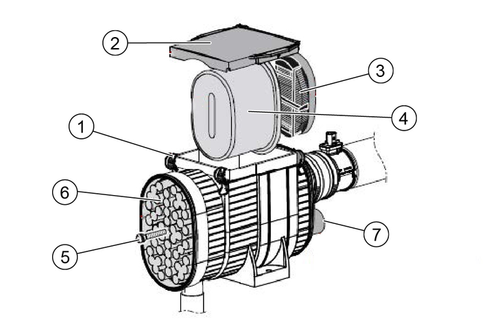
Open the locking hooks on the air filter housing.
Remove the air filter housing cover.
Open the screw and remove the preliminary filter.
Clean the preliminary filter with compressed air or a water jet.
Remove the filter inlay and safety filter.
Tap out both filters and clean them with an outward-directed compressed air jet, replace as needed or according to the maintenance plan.
Clean the interior of the air filter housing.
Check that the sealing surfaces and suction channels are clean and undamaged.
Install all cleaned filters again.
Risk of fatal injury from flowing road traffic
Bring the vehicle out of the hazard zone of flowing road traffic before starting any repair work.
Switch on the warning flashers.
Erect a warning triangle.
Don warning clothing.
Risk of injury due to sinking vehicle
Do not stand under the vehicle raised only with a jack.
Danger of accident
Ensure that the ground is level and solid. If necessary, place a large-scale, stable surface under the jack.
Perform the wheel change only if you are familiar with the necessary steps for changing a wheel. Otherwise, seek expert assistance.
Use only suitable and undamaged tools for changing a wheel.
Use a suitable commercial jack with a lifting capacity of at least 5000 kg.
Park the vehicle on level and solid ground.
Remove the ignition key.
Secure the vehicle against rolling away (e.g. with wheel chocks).
Use a suitable tool to release the wheel nuts by approx. 1 turn.
Position the jack at the jacking point and lift the vehicle.
Additionally support the vehicle safely.
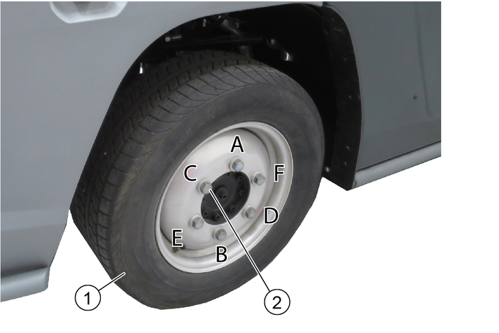
Unscrew the wheel bolts.
Remove the wheel.
Clean dirty wheel bolts.
Fit the new wheel and screw in all wheel bolts with washers all the way to the end stop, do not tighten with full torque.
Tighten the wheel nuts step by step in the specified sequence (A - F).
Lower the vehicle with the jack.
Finally, tighten the wheel bolts in the specified sequence using a correctly working torque wrench to 330 Nm.
Re-tighten the wheel bolts after 50 - 100 km.
Danger of burns
Do not touch any hot surfaces such as the exhaust pipe, SCR catalytic converter, motors or gearbox components.
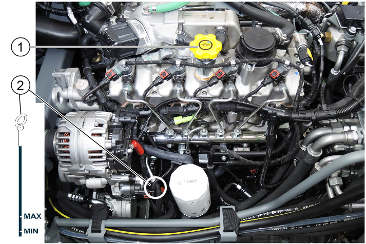
Check the engine oil level only when vehicle is level.
Bring the engine to operating temperature (70 - 80 °C).
Stop the engine and wait a few minutes so that the complete oil can drain into the oil pan.
Open the fresh water tank latch at the left (bonnet) with a square wrench.
Pivot the fresh water tank to the side.
Measure the oil level using the oil dipstick.
If the oil level is below the lower marking (MIN), add engine oil in small steps (100 - 200 ml) until the correct oil level is reached.
For the correct oil type see chapter "Technical data".
The engine oil and engine oil filter may only be replaced by authorized Customer Service.
After every oil change, the function (calculation of the oil dilution) must be reset with a diagnostic instrument.
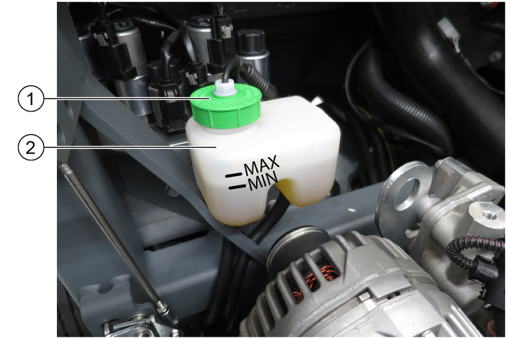
Check the brake fluid level in the reservoir regularly.
The fluid level must lie between the MIN and MAX markings.
If the brake fluid level in the reservoir falls below MIN, the indicator light lights up.
Top up brake fluid to MAX.
If the indicator light lights up again after a short period of operation, have the brake system checked for leaks by an authorized Customer Service.
Park the machine securely.
Replacement of the brake fluid must only be carried out by the authorized Customer Service according to the inspection checklist (ICL).
Danger of burns
Do not touch any hot surfaces such as the exhaust pipe, SCR catalytic converter, motors or gearbox components.
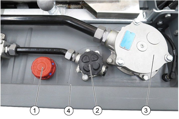
If the "Water in fuel" indicator is lit, proceed as follows.
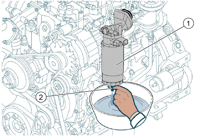
Switch off the ignition and remove the ignition key.
Allow the engine to cool sufficiently.
Provide containers of adequate capacity.
Unscrew the sensor on the water separator.
Drain fuel until no more water is contained.
Be careful not to spill all the fuel out of the filter in the water separator, otherwise the fuel filter must be removed, refilled and the system vented.
Tighten the sensor again.
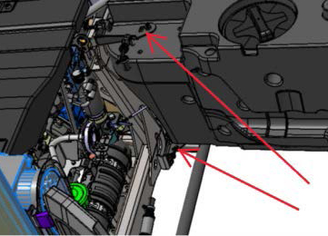
The following description only applies if the engine is not functional and no hydraulic pressure is available (e.g. for towing or loading).
Risk of burns from hot surfaces
Allow the vehicle to cool down before working on it.
Risk of accident due to rolling away
Release the parking brake only when the vehicle is secured against rolling away.
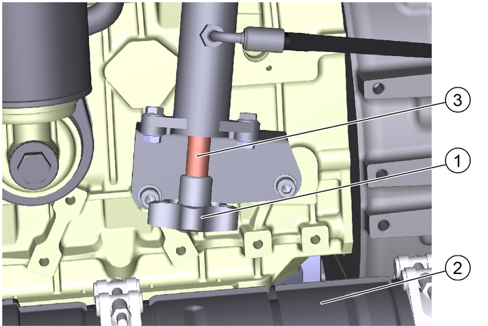
Figure: Emergency operation in position A
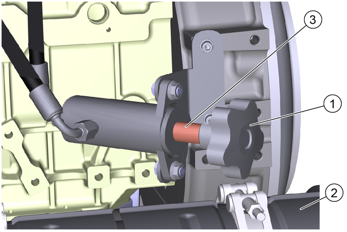
Figure: Emergency operation in position B
Open the left side panel lock with the square wrench.
Pivot the side panel outwards.
Completely unscrew the star grip counterclockwise. Remove the sleeve.
Turn the star grip clockwise, thereby building up the hydraulic pressure to release the parking brake.
After towing: Unscrew the star grip completely, put the sleeve back on and tighten the star grip.
Clean the vehicle daily after finishing work.
Risk of damage through incorrect cleaning
Do not clean joints, tyres, radiator fins, hydraulic hoses and valves, seals, electrical and electronic components using a high-pressure cleaner.
Observe the respective safety regulations when cleaning the vehicle with a high-pressure cleaner.
Do not use aggressive detergents.
Wash the vehicle only when the engine is switched off to protect the air filter.
To avoid the risk of fire: Check the vehicle for oil and fuel leakage. Have leaks repaired by Customer Service.
To avoid the risk of fire: Clean the engine, muffler and battery of plant residues and oil.
If necessary, clean the engine with a brush, compressed air or with low water pressure if necessary.
Clean the mudguards/wheel arches.
Risk of injury from sharp edges
Use protective gloves for cleaning.
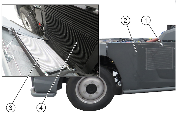
Charge air, water and hydraulic oil cooler
Release the side panel lock with a square wrench.
Tilt the panel outwards, a safety rope holds it in position.
Manually remove coarse dirt from the radiator.
Use a soft brush or broom to clean with compressed air (5 bar max.) or low water pressure.
The fuses in the driver's cab are located behind a cover on the middle rear wall of the cab.
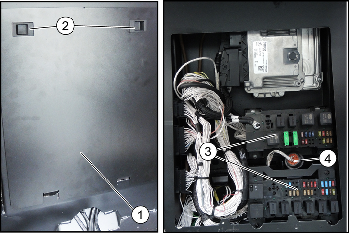
Fold the passenger seat backrest forward.
Open the cover latches then tilt the cover and remove it upwards.
Replace defective fuses.
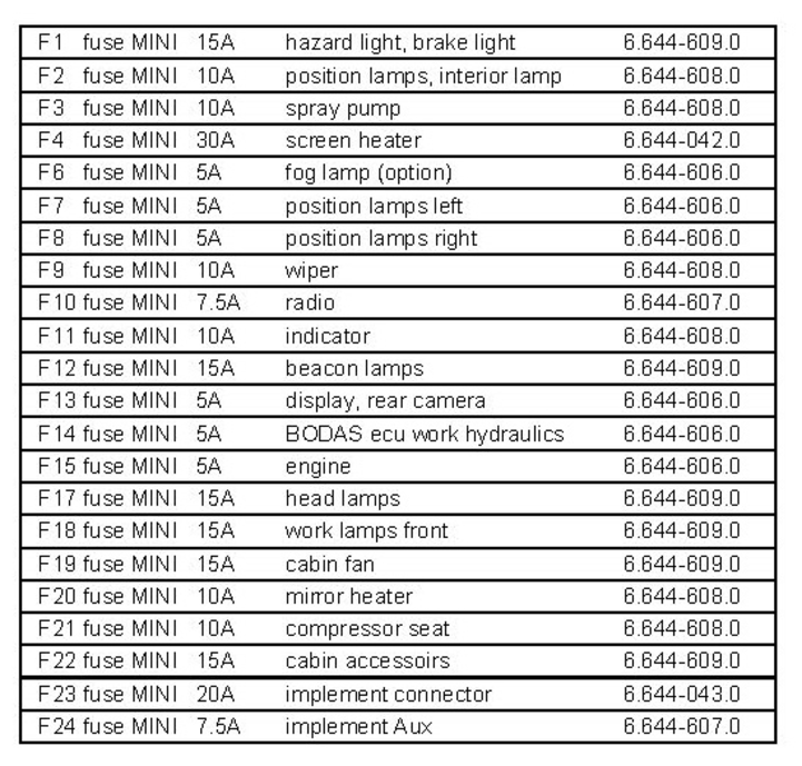
Use only fuses with the same ampere rating.
The next fuses are located on the vehicle behind a cover on the right side panel.
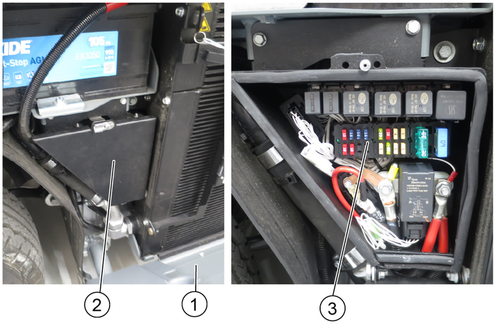
Release the side panel lock with a square wrench.
Tilt the panel outwards, a safety rope holds it in position.
Open the cover latch and remove the cover.
Replace defective fuses.
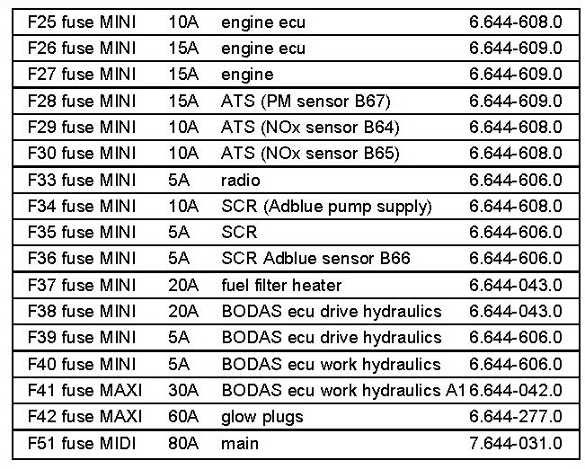
Use only fuses with the same ampere rating.
Risk of injury and damage
Be aware of the weight of the vehicle.
Park the vehicle in a protected, level and dry place.
If there is a danger of frost, check that there is enough antifreeze in the coolant.
Clean the vehicle inside and out.
When stored for more than one month:
Jack up the vehicle (freely rotating wheels).
Disconnect the battery, recharge every 2 months.
When restarting after prolonged storage, carry out scheduled maintenance as necessary.
You can remedy minor faults using the following overview.
If in any doubt, please contact your authorised Customer Service.
Risk of electric shock
Switch off the vehicle before carrying out any care and maintenance work, and remove the key.
Repair work and work on electrical components must only be performed by your authorised Customer Service.
Remedy:
Check / charge the battery.
Sit in the driver's seat (seat contact switch is activated).
Set the driving direction lever to the NEUTRAL position - central position.
Fill up fuel, bleed the fuel system.
Check, clean and/or replace the fuel filter.
Check the fuel connections and lines.
Contact an authorised Customer Service department.
Cause:
Remedy:
Clean/replace the air filter.
Check, clean and/or replace the fuel filter.
Fill up fuel, bleed the fuel system.
Check the fuel connections and lines.
Contact an authorised Customer Service department.
Remedy:
Check the filling level of the hydraulic oil tank.
In the event of freezing temperatures and cold hydraulic oil: Allow the vehicle to warm up for at least 3 minutes.
Cause:
The engine indicator light (MIL) lights up when the ignition is switched on to check the function.
It notifies the driver of a fault in an emission- or safety-related component.
In the event of active faults, the MIL lights up permanently.
Remedy:
If the fault is no longer active, the light is switched off after 3 driving cycles
In the event of DEF faults, the light goes out already 1 driving cycle after filling up the reaction liquid (DEF)
1 driving cycle =
Switch on the ignition
Start the engine and let it run for at least 5 seconds
Switch off the engine and wait for the afterrun (approx. 30 seconds)
Cause:
Engine fault in the exhaust treatment system
Informs that the exhaust aftertreatment is impaired.
Remedy:
Eliminate the error in order to get the vehicle fully functional again; this prevents damage to the engine and vehicle
Check the level in the DEF reservoir
Minimum engine run time after topping up is 20 minutes. Then the warning lamp goes out.
Cause:
Regeneration process required.
Remedy:
Perform regeneration (see chapter "Regeneration").
Cause:
Regeneration process has generated an error (NOx monitoring unit).
Remedy:
Call Customer Service.
Cause:
Engine oil pressure is too high.
Remedy:
Call Customer Service.
Cause:
Fault in the drive.
Remedy:
Call Customer Service.
Cause:
Parking brake active.
Remedy:
Release the parking brake.
Cause:
Low fuel level.
Remedy:
Top up the fuel.
Remedy:
Vent the fuel system if the tank was run dry.
Cause:
Coolant temperature is too high.
Remedy:
Switch off the motor.
Clean the radiator (see chapter "Cleaning the radiator").
Check the level of coolant in the motor, refill as necessary.
If the warning light does not go out within 5 minutes:
Switch off the engine
Contact Customer Service
Cause:
Hydraulic oil temperature too high.
Remedy:
Operate the engine in idling mixture until the warning light goes out.
Cause:
Hydraulic oil level is too low.
Remedy:
Top up the hydraulic oil.
Cause:
Hydraulic oil temperature too low.
Remedy:
Carefully warm up the engine until the warning light goes out.
Cause:
Hydraulic oil filter malfunction
Remedy:
Filter dirty or oil too highly viscous (viscous)
Heat the hydraulic oil to at least 40°C by operating the vehicle. If the fault is still active: Contact Service.
Cause:
Service required.
Remedy:
Have the device serviced by Customer Service.
The service display must be reset by Customer Service.
Device performance data | |
Travel speed | 20, 25, 30, 40, 50, 60
The speed may be limited depending on the variant and country specific requirements. The limitation is secured by software. km/h |
Travel speed, backwards | 20 km/h |
Working speed | 20 km/h |
Working speed (max.) | 40 / winter km/h |
Climbing ability (max.) | 25 % |
Turning circle | 2,06 (Dwi) m |
Electrical system / battery | |
Battery type | Maintenance-free - |
Working voltage of the battery | 12 V |
Battery capacity | 105 Ah |
Dimensions and weights | |
Length | 4.248 +/- 30 mm |
Width | 1.300 mm |
Height | 1.990 +10/-20 mm |
Net weight (transport weight) | 2500-2800
(depending on the equipment as a tractor) kg |
Approved total weight | 6000 kg |
Maximum permissible front axle load | 2700 kg |
Maximum permissible rear axle load | 3300 kg |
Trailer coupling vertical load | 300 kg |
Trailer load, inertia-braked | 3000 kg |
Unbraked trailer load | 750 kg |
Permissible inertia-unbraked total gross weight | 9000 kg |
Permissible unbraked total gross weight | 6750 kg |
Operating materials | |
Fuel type | Diesel
(in accordance with DIN EN 590) BIODIESEL can be mixed up to 7% (according to UNI EN 14214) |
Fuel tank capacity | 70 |
Engine oil type | Shell Rimula R6 LM
(ACEA E6 - SAE 10W-40) |
Engine oil volume | 13,2 l |
Type of coolant | Glysantin G 40
(ASTM D 3306) |
Amount of coolant | 14 l |
Type of hydraulic oil | Renol B HV 46
(ISO 11158) |
Hydraulic oil quantity | 55 l |
Grease | EP lithium soaps
(NLGI 2)
Observe the lubrication point symbols on the device |
<data>Engine type </data> | VM R754EU6C (Euro 6) | VM R754ISE5 (Stage V) | |
|---|---|---|---|
<data>Type </data> | Four-cylinder 4-stroke diesel engine DPF and SCR system | Four-cylinder 4-stroke diesel engine DPF system | |
<data>Cooling type </data> | Water cooling | Water cooling | |
<data>Engine capacity </data> | <data>cm3 </data> | 2970 | 2970 |
<data>Engine performance </data> | <data>kW/PS </data> | 75 / 102 | 54.5 / 74 |
<data>Engine speed </data> | <data>1/min </data> | 2300 | 2300 |
<data>Noise at the driver's ear according to Regulation (EU) 1322/2014, App. XIII </data> | <data>dB(A) </data> | 73 (closed) 79 (open) | 73 (closed) 79 (open) |
<data>Vibration value, whole body, according to VO (EU) 1322/2014, App. XIV </data> | <data>m/s2 </data> |
|
|
Kenda 235/65R 16C KR33A | Reference axle load 1450 kg | Maximum axle load 3300 kg |
Tyre inflation pressure front axle + rear axle in kPa (bar) | 550 (5.5) | 680 (6.8) |
Michelin 235/65R 16C 121/119R M+S Agilis Alpin | Reference axle load 1450 kg | Maximum axle load 3300 kg |
Tyre inflation pressure front axle + rear axle in kPa (bar) | 550 (5.5) | 670 (6.7) |