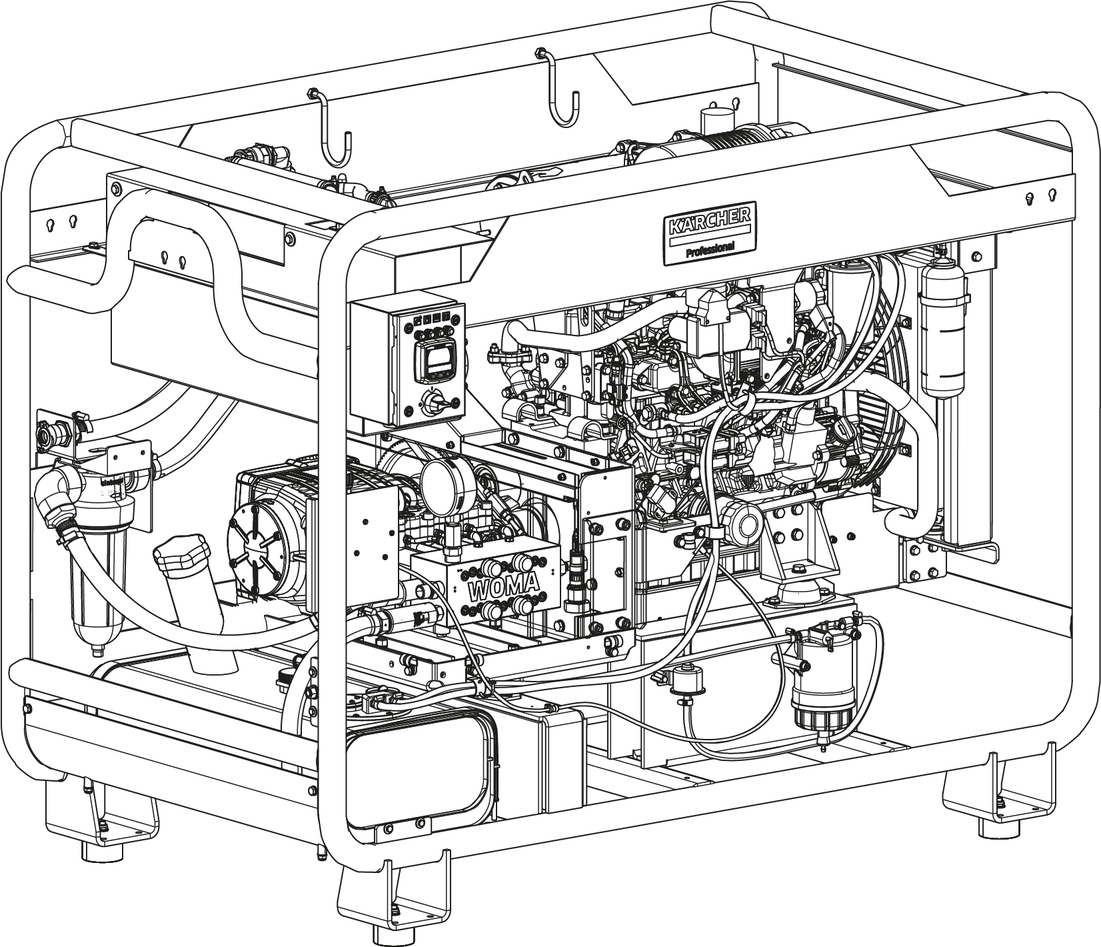
HD 9/100 De Skid *EUHD 9/100 De Skid *KAPHD 9/100 De Skid Advanced *EUHD 9/100 De Skid Advanced *KAP
59690740 (09/22)
59690740 (09/22)
 Read these original operating instructions and the enclosed safety instructions before using the device for the first time. Proceed accordingly.
Keep both books for future reference or for future owners.
Use this high-pressure cleaner for cleaning machines, vehicles, buildings and tools.
Use the device only with accessories and spare parts approved by KÄRCHER.
An isolating device must be present between the nozzle and device (e.g. a high-pressure gun with closing valve, a pressure switching valve or a foot actuated stop valve).
The device should only be used with a high-pressure gun which, when closed, discharges the water pumped by the device to the atmosphere in a depressurised manner.
To ensure proper functionality of the combustion engine, the device must not be operated at an altitude in excess of 1676 m above sea level.
Dirty water
Premature wear and tear or deposits in the device
Supply the device using only clean water, or recycled water that does not exceed the specified limit values.
The following limit values apply to the water supply:
Upstream water filter: ≤10 µm
Solid body content: maximum 50 mg/l
Total hardness: 3-15° dH, 30-150 mg/l CaO, 54-268 mg/l CaCO3
Calcium hardness: 0.89-2.14 mmol/l
pH value: 6.5-9.5
Base capacity pH 8.2: 0-0.25 mmol/l
Total dissolved substances: 10-75 mg/l
Electrical conductivity: 100-450 µS/cm
Chloride, e.g. NaCl: <100 mg/l
Iron, Fe: <0.2 mg/l
Fluoride, F: <1.5 mg/l
Free chlorine, Cl: <1 mg/l
Copper, Cu: <2 mg/l
Manganese, Mn: <0.05 mg/l
Phosphate, H3PO4: <50 mg/l
Silicate, SixOy: <10 mg/l
Sulphate, SO4: <100 mg/l
 The packing materials can be recycled. Please dispose of packaging in accordance with the environmental regulations.
 Electrical and electronic appliances contain valuable, recyclable materials and often components such as batteries, rechargeable batteries or oil, which - if handled or disposed of incorrectly - can pose a potential threat to human health and the environment. However, these components are required for the correct operation of the appliance. Appliances marked by this symbol are not allowed to be disposed of together with the household rubbish.
Current information on content materials can be found at: www.kaercher.com/REACH
Only use original accessories and original spare parts to ensure fault-free and safe operation of the device.
Information on accessories and spare parts can be found at www.kaercher.com.
Protective suit against high-pressure water jets with arm and leg protectors.
High-pressure resistant to a maximum of 100 Mpa (flat jet nozzle).
Size | Order number |
|---|---|
M | 6.547-055.0 |
L | 6.547-056.0 |
XL | 6.547-057.0 |
The catching fixture connects the high-pressure hose to an attachment point on the device or high-pressure gun. It secures the high-pressure hose against whipping away if the hose connection is unintentionally released.
Catching loop (textile): Order number 9.920-368.0
Catching loop (steel rope): Order number 9.887-583.0
Fastening rope (steel rope): Order number 6.025-311.0
Check the contents for completeness when unpacking. If any accessories are missing or in the event of any shipping damage, please notify your dealer.
It is essential that you read the safety instructions 5.963-314.0 before initial startup.
Observe the national regulations for liquid jet cleaners.
Observe the national accident prevention regulations. Liquid jet cleaners must be tested regularly. The test result must be recorded in writing.
Do not modify the device or accessories.
Danger of burns
The exhaust pipe becomes hot during operation and can cause burns if touched.
Do not place the spray unit onto the spray lance storage hooks when the exhaust pipe is hot.
Do not operate the device if fuel has been spilled. In such a case, move the device to another location and avoid any sparking.
Do not store fuel in the proximity of naked flames or devices such as ovens, heating boilers, water heaters, etc. that have a pilot light or may generate sparks. Do not use or spill fuel in the above environment.
Never remove the petrol cap when the engine is running.
Do not use diesel fuel as a detergent or cleaning agent.
When refuelling, make sure a sufficient distance is maintained from sparks, open flames and other ignition sources.
Do not overfill the tank.
Keep easily flammable objects at least 2 m away from the muffler.
Do not operate the device without a muffler. Check the muffler regularly and clean or replace it if necessary.
Do not operate the device in forests, bushy or grassy areas if the exhaust pipe is not equipped with a spark catcher.
Do not run the motor with the air filter removed or without a cover over the intake opening.
Do not adjust any control springs, governor control linkage or other parts that could increase the speed of the motor.
Do not touch any hot parts such as the muffler, cylinder or cooling fins.
Never bring your hands and feet close to rotating parts.
Never operate the device in confined spaces.
Do not use unsuitable fuels as they can be dangerous.
The fuel system is pressurised. Wear eye protection when performing any maintenance work on the fuel system.
Engine coolant can splash out and cause severe burns. Never remove the filler cap when the engine is still warm.
A high pressure jet of fuel can result in severe injury. Avoid contact with a jet of fuel. Never examine fuel leaks by hand.
Contact with engine coolant can result in minor or moderate injury. Wear eye protection and protective gloves when handling engine coolant. If you do come into contact with the coolant, rinse it off by using plenty of clean water.
Risk of damage. Never activate the starter motor when the engine is running.
Risk of damage: Never use start-up aids such as ether.
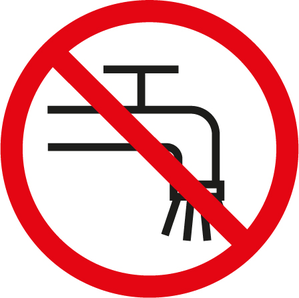 The device may not be connected to the public drinking water network.
 The high-pressure jet must not be directed at persons, animals, live electrical equipment or at the device itself. Protect the device from frost.
 Always wear hearing protection and safety goggles when working with the device.
 Hot surface. Danger of burns. Do not touch. Only use the spray lance storage hooks for transport when the engine has cooled down.
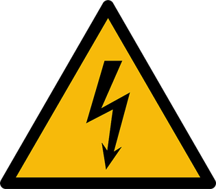 Dangerous electrical voltage. Access only for qualified electricians.
 Crushing hazard posed by the belt drive! Do not remove the protective cover. Do not reach underneath the cover.
 Risk of damage to the high-pressure pump. Only regenerate the diesel particulate filter if the device is connected to a functioning water supply.
Observe the following warnings when handling the batteries:
 | Observe notes in the instructions for the battery, on the battery and in these operating instructions. |
 | Wear eye protection. |
 | Keep acids and batteries away from children. |
 | Risk of explosion |
 | Fire, sparks, open flames and smoking are prohibited. |
 | Risk of acid burns |
 | First aid |
 | Warning |
| Disposal |
| Do not throw batteries in the bin. |
Missing or modified safety devices
Safety devices are provided for your own protection.
Never modify or bypass safety devices.
The safety devices are set and sealed by the manufacturer. Adjustments are performed only by customer service.
The safety valve opens when the permissible operating pressure is exceeded and the water flows into the open.
The key-operated switch prevents the device from being started up unintentionally. Turn the key-operated switch to “0” when taking a break or finishing work and then remove the key.
The safety latch on the high-pressure gun prevents the high pressure water jet from being triggered unintentionally.
Only the Advanced version has this function.
When the high-pressure gun is closed, the overflow valve with pressure relief opens and all the water flows back to the suction side of the high-pressure pump. The pressure in the high-pressure hose drops. This reduces the actuating force of the high-pressure gun and extends the service life of the device.
The water shortage safeguard switches off the motor if the water supply is inadequate.
The water shortage safeguard indicator light lights up.
Only the Advanced version has this function.
The thermostat valve protects the high-pressure pump from overheating in circulation mode when the high-pressure gun is closes. The thermostat valve opens when the water temperature exceeds 80 °C and channels the hot water into the open.

* for Advanced version
** for Standard version

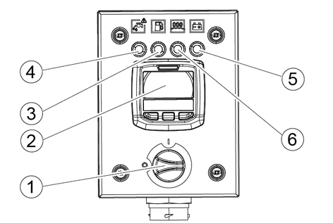
Only EU version devices are equipped with the display.
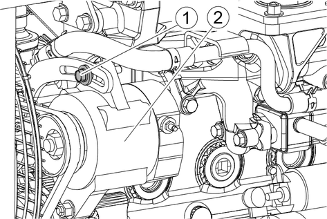
Remove the transport screw from the oil filling nozzle of the high-pressure pump.
Screw in and tighten the venting screw with oil dipstick supplied.
Connect the battery cable to the positive terminal of the battery.
This system establishes the connection between the spray lance and high-pressure gun and also between the spray lance and nozzle.
Check the screw connection and connection for damage. Do not use damaged parts.
Screw the pressure ring far enough onto the spray lance or hose connection so that approximately 2 thread turns are visible before the pressure ring.
Note: The pressure ring has a left-hand thread.
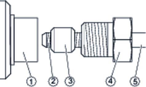
Fit the spray lance with pressure piece into the high-pressure connection.
Push the pressure screw onto the pressure ring.
Screw in and tighten the pressure screw (tightening torque 160 Nm).
Install accessories only when the device is switched off.
Note: Observe the separate operating instructions for the “Dump gun” high-pressure gun.
Connect the spray lance to the high-pressure gun.
Check the high-pressure hose (see section "Care and maintenance/maintenance intervals/Before each use").
Lightly the grease the thread on the high-pressure hose and on the device/gun.
Connect the high-pressure hose to the high-pressure gun. Maximum hose length 40 m, DN 6.
Connect the high-pressure hose to the high-pressure connection.
Fit the nozzle holder onto the spray lance.
Insert the nozzle into the nozzle holder.
Screw on the union nut and hand-tighten.
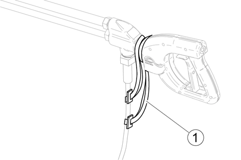
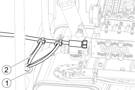
Secure the high-pressure hose on the high-pressure gun.
Secure the high-pressure hose on the device.
Risk of damage
Risk of damage
An excessive inclination can result in damage to the engine.
Certain operating conditions can reduce engine performance and cause premature wear of the engine.
Do not start the device if the angle of inclination exceeds 15°.
If the device is inclined, secure it to prevent it from tipping over.
Avoid operating the device in extremely dusty conditions, or if there is a presence of chemical gases, vapours or salt spray. Protect the engine from rain and flooding.
Never operate the engine without an air filter insert present.
Perform maintenance work prior to each operating procedure (see “Care and maintenance”).
Only refuel with diesel fuel. The fuel must be free of any impurities.
Remove the cap from the filling nozzle of the fuel tank.
Pour fuel into the filling nozzle and, when doing so, observe the filling level display.
Stop the filling process when the pointer of the filling level display points to “F”. Do not overfill the tank.
Place the cap on the filling nozzle and secure it in place.
Position the device on a level surface.
The oil level must be in the middle of the oil level indicator or the oil dipstick.
Top up with oil if necessary (see "Technical data")
Return flow of dirty water into the drinking water network
Health risk
Observe the regulations of your water supply company.
According to applicable regulations, the device must never be used with the drinking water network without a system separator. Use a system separator from KÄRCHER or a system separator as per EN 12729 Type BA. Water that has flowed through a system separator is classified as undrinkable. Always connect the system separator to the water supply and never directly to the water connection on the device.
Check the supply pressure, supply temperature and supply volume of the water supply (see "Technical data" section).
Risk of damage due to foreign bodies
Non corrosion-resistant or dirty hoses can release particles that are damaging to the device.
Use only corrosion-resistant, clean hoses.
Connect the system separator to the water connection of the device using a water supply hose (for the requirements placed on the water supply hose see the "Technical data" section).
Route the high-pressure hose so that it cannot be damaged by mechanical influences or vibrations.
Open the water inlet.
Risk of damage
Damage due to cavitation can occur if air is present in the high-pressure pump during operation.
Do not open the high-pressure gun during the venting process.
Connect the high-pressure hose and the high-pressure gun.
Ensure the required minimum water supply volume (see "Technical data").
Open the water inlet.
Classic version: Water flows out of the bypass pipe.
Advanced version: The float container fills with water
Open the venting screw at the filter until all air has escaped from the filter.
Close the venting screw.
Start the engine (see “Operation”).
Pull the breather hose away from the device. Water escapes here during the venting process.
Open the pump venting lever until an even flow of water escapes from the breather hose; do this for at least 90 seconds.
Close the pump venting lever.
The water shortage safeguard switches the device off in the case of insufficient advance pressure.
In this case, turn the key-operated switch to “0” to reset the water shortage safeguard.
Restart the engine to continue the venting process.
Keep switching the device Off/On until it runs fault-free in depressurised circulation/idle mode.
Vent the low-pressure system as described above.
Remove the high-pressure nozzle.
Pull and hold the trigger of the high-pressure gun with the motor at a standstill.
Wait until an even flow of water escapes from the spray lance (wait at least 90 seconds).
Release the trigger of the high-pressure gun.
Turn the trigger to 1/ON.
A high-pressure water jet is emitted from the spray lance, even when operating without a high-pressure nozzle.
The high-pressure jet can cause injuries.
Do not point the spray lance at people.
Pull the trigger of the high-pressure gun and hold it until an even water stream is emitted.
If the device exhibits pulsing behaviour for a longer period of time when the high-pressure gun is open, turn the trigger to 0/OFF.
Turn the trigger to 1/ON to continue venting.
Keep switching the device Off/On until an even water stream is emitted.
The control panel can be positioned at 5 locations on the frame of the device. This allows the most favourable position to be selected for every application.
Slide the control panel upwards and pull it away from the frame of the device.
Align the bolts at the rear of the control panel with the holes of the selected mounting position.
Press the control panel onto the tubular frame and engage it in position.
Route the high-pressure hose so that it cannot be damaged by mechanical influences or vibrations.
Do not route the hose under tension because pressure changes can alter the length of the hose.
Do not bend it beyond the smallest permissible ´bending radius.
Do not twist the hose (torsion).
Avoid abrasion on other hoses, moving parts, edges rough surfaces.
Protect loosely routed hoses against damage, abrasion and deformation by using hose bridges.
Connect the hose end with and inner thread first if the other hose end has a union nut.
Do not use sealants (e.g. hemp, sealing tape).
Adhere to the design specifications of the valve when connecting to a valve (e.g. multiple-consumer valve).
Protect hoses from sunlight and heat.
Secure the high-pressure hose to the device and high-pressure gun suing hose safety catches.
Risk of injury due to uncontrolled emission of a maximum-pressure water stream.
A maximum-pressure water stream can cause fatal injuries.
Perform the following checks each tie before starting operation.
Check that the high-pressure gun is correctly installed.
Check that the high-pressure gun is correctly connected to the high-pressure cleaner.
Check that the water supply satisfies the requirements in the "Technical data" section and is correctly implemented.
Vent the high-pressure cleaner as described in the "Water connection" section.
Rinse the high-pressure cleaner, hose and high-pressure gun with fresh water while depressurised.
Check that the device corresponds to the as-delivered state and that no impermissible modifications have been made.
Check to ensure the trigger and safety latch move freely:
The trigger must independently return to the initial position and engage in the safety latch when released.
It should only be possible to actuate the trigger when the safety latch is actuated.
With the device switched off, check that the water stream is immediately emitted at the bypass pipe when the trigger is released.
Repeat step 2 while the device is running.
The working pressure is shown on the pressure gauge.
Always initially direct the high-pressure jet at the object to be cleaned from a distance to avoid damage due to excessive pressure.
Open the water inlet.
Vent the device (see chapter "Venting the device").
Turn the fuel cock to the “ON” position.
Raise the engine speed lever as far as possible (to the lowest speed).
Turn the key-operated switch to position “1”.
Wait until the engine preheating indicator lamp goes out.
Risk of damage
The starter can overheat.
Interrupt the start-up attempt if the engine does not start after 15 seconds. Wait at least 30 seconds between 2 start-up attempts.
Turn the key-operated switch beyond position “1” until the engine starts.
Release the key-operated switch; it will automatically return to position “1”.
Unlock the high-pressure gun.
Dump gun: Press the safety latch of the high-pressure gun downward.
Dry shut: Pivot the safety latch of the high-pressure gun upward.
Risk of injury due to forces at the high-pressure hose during pressure changes
The user can loose balance and fall due to movement of the high-pressure hose.
Assume a stable posture before using the device.
Pull the trigger.
Adjust the working pressure by adjusting the engine speed lever. Do not exceed 100 MPa (1000 bar).
Increase speed - Lower the engine speed lever.
Decrease speed - Raise the engine speed lever.
If the EU version is operated at a lower engine speed or in an idle mode for a prolonged period, the diesel particulate filter will need to be regenerated more frequently. The risk of damage to the diesel particulate filter also increases.
Release the trigger.
The safety latch secures the trigger against unintentional operation.
Turn the key-operated switch to position “0”.
Risk of injury due to an uncontrolled high-pressure water jet.
A high-pressure water jet can cause fatal injuries.
Never hang up the high-pressure gun by the trigger but rather by the gun housing.
Risk of injury due to uncontrolled emission of a maximum-pressure water stream.
A maximum-pressure water stream can cause fatal injuries.
Perform the following checks each time before resuming work.
Check that the high-pressure gun is correctly installed.
Check that the high-pressure gun is correctly connected to the high-pressure cleaner.
Check that the system is vented.
With the device switched off, check that the water stream is immediately emitted at the bypass pipe when the trigger is released.
Repeat step 4 while the device is running.
Actuate the high-pressure gun several times in a safe location with the device switched on and check the valves at the bypass and leakage bores for leaks.
Check to ensure the trigger and safety latch move freely:
The trigger must independently return to the initial position and engage in the safety latch when released.
It should only be possible to actuate the trigger when the safety latch is actuated.
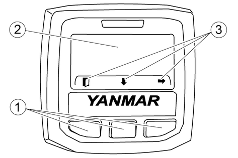
The function of the buttons changes depending on the operating state.
The current function of each button is indicated above the button in the display.
If the display of the button functions is hidden, it can be activated by pressing any button.
Explanation of the button functions:
 | MAIN MENU Jump directly to the main menu |
 | EXIT MENU Jump back one menu level |
 | SCROLL Call up the next display |
 | UP Move upwards in the menu |
 | DOWN Move downwards in the menu |
 | NEXT Select the highlighted menu item |
 | Button + Increase the selected value |
 | Button - Decrease the selected value |
 | CONFIRM Confirm the entry |
 | ? button Call up further information |
This menu can be used to set the properties of the display. The measuring units for pressure, temperature and volume can also be selected.
Press the MAIN MENU button.
Select the “Display Setup” menu by using the DOWN button.
Press the WEITER button.
Select the desired submenu by using the DOWN button.
Make your selection by using one of the following two functions.
Select one of the suggestions offered by using the SCROLL button.
Press NEXT to open the corresponding specification in % and alter the value.
Display | Meaning |
|---|---|
Language | Display Language |
Display Mode | Configuration of the display |
Single | One measured value per window |
Dual | Two measured values per window |
Backlight | Display lighting |
Contrast | Display contrast |
Pressure Units | Measuring unit for pressure (bar, kPa, psi) |
Temp Units | Measuring unit for temperature (C, F) |
Volume Units | Measuring unit for volume (l, gal) |
The display can show either 1 or 2 pieces of operating data simultaneously.
Proceed as described in the chapter “Display settings”.
Single | 1 value is shown in the display. |
Dual | 2 values are shown side by side in the display. |
When the basic state is selected, the display shows the operating data of the engine.
Press the SCROLL button to scroll through the various displays.
The last displayed value (Single) or the last two displayed values (Dual) are displayed continuously until the selection is changed again.
Display | Meaning |
|---|---|
Ash Load | Ash loading level |
Barometric Pressure Barometer | Air pressure |
Battery Voltage Battery | Battery voltage |
Coolant Temp | Coolant temperature |
DOC Inlet Temp DOC Inlet C | Diesel particulate filter inlet temperature |
DOC Outlet Temp DOC Outlet C | Diesel particulate filter outlet temperature |
Engine Hours Eng Hours | Engine operating hours |
Engine Load Eng Load | Engine performance |
Engine Speed Engine RPM | Engine speed |
Exhst Manifold Press Exhaust Mnfld BAR | Exhaust gas pressure |
Fuel Rail 1 | Injection pressure |
Fuel Rate | Fuel consumption |
Fuel Temp | Fuel temperature |
Intake Fresh Air Intake Temp C | Intake air temperature |
Intake Manifold Press Intake Mnfld BAR | Air pressure of intake manifold |
Intake Manifold Temp Intake Mnfld C | Temperature of intake manifold |
Maintenance | Time until next service is due |
Requested Speed | Target speed |
Soot Load | Soot loading level |
Throttle Percent Throttle % | Throttle position |
The main menu contains the following submenus:
Display | Meaning |
|---|---|
Fault Codes | Error messages (see chapter “Help in the event of faults”) |
Reset Maint Timer | Resetting the maintenance counter |
Engine Settings | Engine settings (only accessible to authorised service personnel) |
Regeneration | Regeneration of the diesel particulate filter (see chapter “Maintenance/Regenerating the diesel particulate filter”) |
Display Setup | Display settings |
About | Information regarding the display version |
Press the MAIN MENU button.
Use the UP and DOWN buttons to find the required submenu.
Open the submenu by pressing the “NEXT” button.
Press the MAIN MENU button.
Select the “About” menu by using the DOWN button.
Press the WEITER button.
Release the trigger.
Set the engine speed lever to the lowest speed.
Let the engine run at a low idle speed for at least 5 minutes before switching it off.
Turn the key-operated switch to "0".
Turn the fuel cock to the “OFF” position.
Close the water inlet.
Pull the trigger of the high-pressure gun until the device is depressurised.
Release the trigger.
The safety latch secures the trigger against unintentional operation.
Unscrew the water supply hose from the device.
Store the high-pressure hose and accessories on the device.
Before shutting down the device for a prolonged period, disconnect the battery cable from the positive terminal of the battery.
The EU version is equipped with a diesel particulate filter. Deposits build up in the diesel particulate filter over time and must be removed by regeneration.
The device can continue to be used during the automatic regeneration process; the cleaning performance does not change.
Automatic regeneration is activated in the delivery state.
If the automatic regeneration function is activated, a regeneration process will be carried out when it is necessary to do so during operation.
Call up the main menu in the display.
Press the DOWN button repeatedly until “Regeneration” is highlighted.
Press the WEITER button.
Use the SCROLL button to select the setting “Allow”.
If the setting “Inhibit” is selected, the automatic regeneration function is deactivated.
“Automatic Regeneration” appears in the display during the regeneration process.
If the operating temperature is too low for regeneration, the display “Increase RPM/Load!!!” appears.
If this message is displayed, increase the engine speed gradually by using the engine speed lever until the message “Automatic Regeneration” appears.
If the automatic regeneration function is deactivated, the message “Regeneration Disabled” will appear in the display as soon as a regeneration process is necessary.
The message then changes to “Automatic Regeneration requested”.
You can choose be between “Allow” and “Delay”.
If the regeneration process is to be carried out immediately, select the function “Allow”.
If the regeneration process is to be carried out at a later date, select the function “Delay”.
The message “Regen requested Allow” appears in addition to the operating display.
The regeneration process can be started at any time by selecting the function “Allow”.
If the regeneration process is not allowed, the request “Automatic Regeneration requested” will appear again after 30 minutes.
If the message “P1463 PM High P Method Above Normal-S” or “P1421 DPF OP Interface Above Normal-MS appears in the display, a stationary regeneration process must be carried out. The device cannot be used during the stationary regeneration process.
The regeneration process lasts between 30 minutes and 2 hours.
The engine must be running to carry out the regeneration process.
Make sure the device is supplied with water.
Risk of damage
If the device is not supplied with water during regeneration of the diesel particulate filter, the high-pressure pump will be damaged as a result of overheating.
It is imperative you ensure the device is supplied with water during the regeneration process.
Fill the fuel tank completely.
Confirm the message “P1463 PM High P Method Above Normal-S” or “P1421 DPF OP Interface Above Normal-MS” by pressing any button on the display.
Confirm the message “P1424 DPF OP Interface Above Normal-S” by pressing any button.
Confirm the query “Begin Recovery Process?” by pressing the “YES” button.
Turn the interlock switch to the “ON” position.

Use the engine speed lever to set the engine to a low speed.
Confirm the message “Bring Machine to Low Idle Speed and confirm interlocks” by pressing any button.
Confirm the query “Start Recorery Process?” by pressing the “YES” button.
The message “Waiting for Recovery to begin” indicates that the regeneration process is being prepared.
The regeneration process is active as long as the message “Recovery active” is displayed. The bar at the bottom shows the progress of the regeneration process.
When the regeneration process is complete, the message “Recovery Regeneration Complete” is displayed.
Confirm the message “Recovery Regeneration Complete” by pressing any button.
Turn the interlock switch to the “OFF” position.
The regeneration process is complete.
It is imperative the device is switched off prior to transport.
Transporting the device in a vehicle: Secure the device in accordance with the respectively applicable guidelines to prevent it from slipping or overturning.
Transporting the device with a forklift: Arrange the forks underneath the tubular frame between the feet.
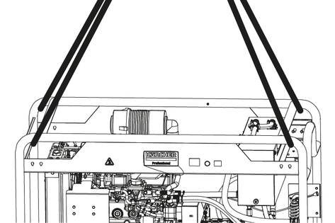
When transporting with a crane, follow the instructions below.
Improper crane transport
Risk of injury from a falling device or falling objects
Observe the local regulations for accident prevention and the safety instructions.
Check the crane lifting gear for damage before each crane transport.
The device may only be transported with a crane by persons instructed in the operation of the crane.
Check the lifting gear for damage before each crane transport.
Check the tubular frame of the device for damage before each crane transport.
Do not lift the device by using the ring bolt on the high-pressure pump or the motor.
Do not use an slinging chains.
Secure the lifting gear against unintentional unhooking of the load.
Remove the spray lance with high-pressure gun and other loose objects before transporting by crane.
Do not transport any objects on the device during the lifting operation.
Do not stand under the suspended load.
Ensure that no persons are in the hazard zones of the crane.
Do not leave the device handing unattended on the crane.
Secure the lifting gear to the tubular frame.
Failure to observe the weight
Risk of injury and damage
Be aware of the weight of the device during transport and storage.
Store the device indoors only.
Storage temperature -20 °C...+40 °C
No corrosive atmosphere.
Vibration-free storage location.
Turn the motor shaft manually by a quarter turn once a week.
High-pressure hoses:
Completely drain the hose.
Close all openings.
Protect the fittings with protective caps.
Observe the maximum storage duration. Ageing impairs the material properties.
Store free of tension and lying down.
Store in a cool, dry and dust-free place.
Avoid direct sunlight or UV radiation.
Shield from sources of heat.
Avoid the vicinity of ozone sources (e.g. fluorescent light sources, mercury-vapour lamps).
Do not bend beyond the smallest permissible ´bending radius.
Frost
Destruction of the device through freezing water
Completely drain the water from the high-pressure pump and water system.
Store the device in a frost-free location.
If frost-free storage is not possible:
Rinse the device with anti-freeze as described below.
Use commonly available, Glycol-based vehicle anti-freeze. Observe the handling instructions of the anti-freeze manufacturer.
Shut off the water inlet
Start the device and operate it with the high-pressure gun open until the float tank is empty.
Interrupt the operation.
Pour approximately 5 litres of anti-freeze into the float tank.
Start the device.
Open the high-pressure gun.
If anti-freeze leaks from the nozzle, close the high-pressure gun.
Keep the device running to flush the bypass system.
Open the pump ventilation lever until anti-freeze comes out of the ventilation hose.
Switch off the device.
Disconnect the spray unit (high-pressure hose and high-pressure gun) from the device.
Use an external pump to feed anti-freeze into the device at the water connection.
Wait until anti-freeze flows out of the bypass pipe of the high-pressure gun.
Open the pump ventilation lever until anti-freeze comes out of the ventilation hose.
Finish feeding in the anti-freeze.
Disconnect the spray unit (high-pressure hose and high-pressure gun) from the device.
Check the engine coolant filling level.
Check the antifreeze range of the engine coolant.
If the device is being stored for 6 months or longer, the following measures must also be carried out.
Carry out the maintenance procedure that is due next.
Flush the radiator and fill it with long life coolant.
Remove any traces of oil and grease from the outside of the engine.
Either completely empty the fuel tank or fill it completely.
Lubricate the engine speed lever.
Disconnect the battery cable from the positive terminal of the battery.
Check the battery acid level and top it up with distilled water if necessary.
Protect the device against the ingress of water and dust.
Charge the battery on a monthly basis during storage.
Let the engine tick over every 4 to 6 months without starting it.
Check the engine (see “Initial startup”).
Establish the water connection for the high-pressure pump.
Vent the low pressure system of the high-pressure pump.
To supply the engine with oil:
Let the engine tick over for 15 seconds without adding any fuel.
Wait 30 seconds.
Carry out this procedure a total of 4 times.
Fill with fuel.
Start the engine.
Operate the engine at idle speed for 15 minutes. When doing this, check for fuel, coolant and oil leaks.
Observe the control displays to ensure they are working correctly.
Check the oil pressure.
Avoid prolonged periods of idle or maximum speed for the time remaining of the first operating hour.
The device can start unintentionally.
Danger of burns
Risk of scalding
The high-pressure water jet or impelled parts can cause injuries.
The engine, especially the muffler, gets hot during operation. Touching hot parts of the engine can result in burns.
Hot engine coolant and steam can escape when the radiator cap is opened and cause severe scalding injuries.
Before starting any maintenance work, set the key-operated switch to “0” and actuate the trigger of the high-pressure gun until the device is depressurised.
Remove the key from the key-operated switch.
Do not start any maintenance work until the engine has cooled down sufficiently.
Do not open the radiator cap until the engine has cooled down.
Tighten the radiator cap firmly.
Risk of damage
Risk of damage
Water ingress will damage the engine.
Incorrect cleaning processes will damage the engine.
Protect the air filter and electrical components before cleaning the engine with water or steam.
Do not use a wire brush to clean the engine.
Do not clean the engine with a water jet exceeding 1.9 bar.
Old oil may only be disposed of at designated collection points. Please dispose of any old oil at these locations. Polluting the environment with old oil is punishable by law.
You can agree on regular safety inspections or close a maintenance contract with your dealer. Please seek advice on this.
Carry out the following checks on the engine every day prior to start-up.
Check for oil leaks.
Check for fuel leaks.
Check for coolant leaks.
Check for damage or missing components.
Check for loose, missing, or damaged connecting elements.
Check the wiring for cracks, abrasion, and damaged or corroded connections.
Check the hoses for cracks, abrasion, and damaged, loose, or corroded holders.
Check the radiator for contamination and, if necessary, clean the cooling fins with compressed air (maximum 0.19 MPa).
Check the water separator for water and contamination; drain the water separator if necessary (see “Maintenance work”).
Check the engine oil level (see “Maintenance work”).
Check the coolant level (see “Maintenance work”).
Check the high-pressure hose.
The operating pressure of the hose must match the operating pressure of the device. (The operating pressure is specified on the hose screw connection.)
The connection threads of the hose and device must match.
The surface of the hose must be undamaged.
The hose screw connections must be free of corrosion, the sealing surfaces and threads must be clean and undamaged.
The O-rings must be present and undamaged.
The hose should not be older than 6 years. (The date of manufacture is specified on the hose screw connection.)
Immediately replace a damaged high-pressure hose.
Check the high-pressure pump oil level at the oil level display.
Contact Customer Service immediately if the oil is milky (water in the oil).
Check the high-pressure pump for leaks.
The device should only be started up if the faults identified during the checks have been rectified.
Check the water filter element.
Check the high-pressure pump for unusual noises.
Clean the device as necessary.
Check the age of the high-pressure hoses. Do not use high-pressure hoses that are more than 6 years old.
Change the oil in the high-pressure pump.
Check the tightening torque of the toothed belt tensioning pulley; nominal value: 150 Nm.
Check the tightening torque of the screws on the pump head (see "Maintenance work").
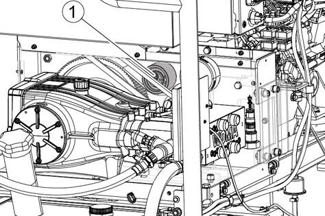
Check the tension of the V-belt on the radiator fan (see “Maintenance work”).
Only applicable for the Advanced version: Check the tension of the V-belt in the advance pressure pump (see “Maintenance work”).
Change the oil and the engine oil filter in the combustion engine (see “Maintenance work”).
Risk of damage
Never clean the radiator with a wire brush. Do not exceed the water pressure specified below.
Check the radiator for contamination and, if necessary, clean the cooling fins with compressed air (maximum 0.19 MPa).
Check the battery.
Check the water separator for water and contamination; drain the water separator if necessary (see “Maintenance work”).
Check the tension of the V-belt on the radiator fan (see “Maintenance work”).
Change the oil and the engine oil filter in the combustion engine (see “Maintenance work”).
Empty the fuel tank (see “Maintenance work”).
Clean or replace the air filter unit.
Only applicable for the Advanced version: Check the tension of the V-belt in the advance pressure pump (see “Maintenance work”).
Check the device for damage.
Clean the engine air intake.
Pay attention to any unusual vibrations.
Check that all screws are tight.
Check the condition of the electrical cable.
Check the motor seals.
Check the high-pressure hoses.
Inspect the surface of the hose for damage (abrasion points, cuts, cracks).
Inspect the hose for deformations (layer separation, blisters, crushing, kinking).
Inspect the hose screw connections for deformation and corrosion
Check that the hose is tightly seated in the hose screw connections.
Have the device serviced by Customer Service.
Change the oil of the high-pressure pump (see “Maintenance work”).
Clean the water separator (see “Maintenance work”).
Replace the fuel filter (see “Maintenance work”).
Replace the air filter insert (see “Maintenance work”).
Drain the coolant from the combustion engine, flush the cooling system and add new coolant.
Have the valve clearance on the combustion engine adjusted by the Yanmar service team.
Have an engine service carried out by the Yanmar service team.
Replace the hoses for the fuel system and cooling system.
Have the valve seats in the combustion engine reground by the Yanmar service team if necessary.
Risk of scalding
The oil in the high-pressure pump becomes very hot and cause scalding if touched.
Do not unscrew the oil drain plug while the device is in operation.
Allow the device to cool down before changing the oil.
See the "Technical data" chapter for the oil volume and type
Unscrew the oil drain plug.
Drain the oil into a suitable collection container.
Screw in the oil drain plug.
Unscrew the cap of the oil filler neck.
Slowly fill with new oil until the level is in the middle of the oil level display.
The air bubbles must escape.
Screw on the cap of the oil filler neck.
Description | Number | Tightening torque |
Cylinder fastening | 1...18 | 40 Nm |
Pump head fastening | 19...22 | 35 Nm |
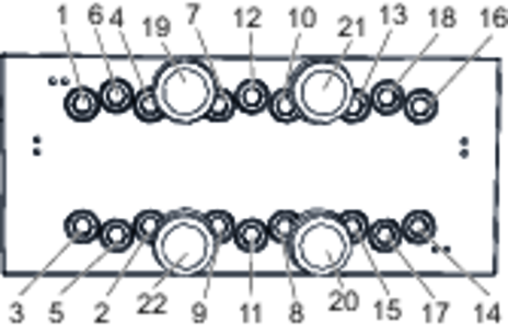
Check all screws for corrosion. Have corroded screws replaced by the Customer Service department.
Set the torque wrench to the value specified in the table above.
Tighten the screws in the sequence 1...22 specified above until the torque wrench clicks to indicate that the correct torque has been reached.
On delivery, the filter is equipped with a filter fleece that retains particles with sizes of 100 µm or larger.
A filter fleece that retains particles with sizes of 50 µm or larger is required when using a rotary nozzle.
Filter fleece | Order number |
|---|---|
100 µm | 6.414-074.0 |
50 µm | 6.414-073.0 |
Close the water inlet.
Unscrew the filter casing.
Replace the soiled filter fleece with a new filter fleece.
Attach the filter casing.
Vent the device.
Turn the key-operated switch to position “0”.
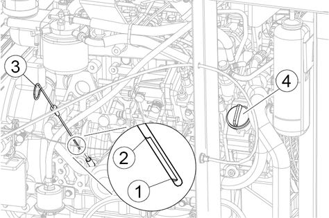
Determine the tension of the V-belt by using an Optibelt frequency meter. Nominal frequency 56...62 Hz.
If the measured frequency deviates from the nominal frequency, the tension of the V-belt must be readjusted.
Check the V-belt for cracks, traces of oil and wear. If the V-belt touches the bottom of the pulley, it means the V-belt is worn.
If the V-belt is damaged, fouled with oil or worn, replace the V-belt.
Loosen the locking screws.
Adjust the tension of the belt by using the tensioning screw.
Tighten the locking screws.
Check the tension of the V-belt.
If necessary, repeat the process until the tension of the belt is correct.
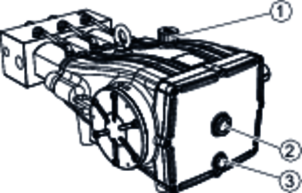
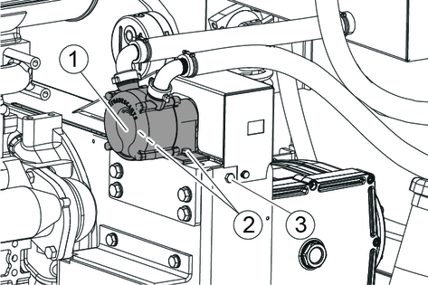
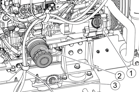
The red float in the lower section of the water separator floats on the water. It indicates whether there is any water in the separator.
Turn the fuel cock to the “OFF” position.
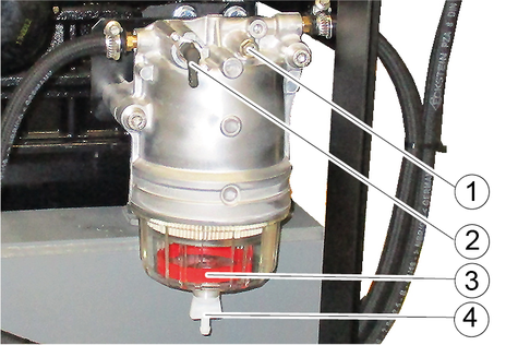
Hold a fuel-resistant container underneath the water separator.
Open the drain tap.
Note: If no water escapes after opening the drain tap, unscrew the venting screw 2...3 revolutions.
Drain the accumulated water (until the red float is located at the bottom of the water separator).
Close the drain tap.
If necessary, tighten the venting screw again.
Turn the fuel cock to the “ON” position.
To vent the fuel system, turn the engine switch to position “1”.
Wait 15 seconds.
Check the water separator for fuel leaks.
The red float in the lower section of the water separator floats on the water. It indicates whether there is any water in the separator.
Turn the fuel cock to the “OFF” position.
Hold a fuel-resistant container underneath the water separator.
Open the drain tap.
Note: If no water escapes after opening the drain tap, unscrew the venting screw 2...3 revolutions.
Drain the accumulated water (until the red float is located at the bottom of the water separator).
Close the drain tap.
If necessary, tighten the venting screw again.
Remove the transparent cap.
Remove the red float from the cap.
Dispose of the contaminated fuel in the cap properly.
Clean the inside of the cap.
Clean the red float.
Clean the filter element in the water separator; replace it if damaged.
Insert the filter element with the O-ring into the support.
Insert the float into the transparent cap.
Check the condition of the O-ring; replace the O-ring if necessary.
Reattach the cap.
Turn the fuel cock to the “ON” position.
To vent the fuel system, turn the engine switch to position “1”.
Wait 15 seconds.
Check the water separator for fuel leaks.
The fuel tank must be emptied on a regular basis in order to remove water and dirt deposits from the tank.
Turn the key-operated switch to position “0”.
Place a suitable container underneath the fuel drain screw.
Remove the cap from the fuel filling nozzle.
Unscrew the fuel drain screw.
Empty the tank until pure diesel fuel flows out.
Reinsert and tighten the drain screw.
Replace the cap of the filling nozzle and tighten it.
Check the fuel tank for leaks.
Stop the engine.
Place the device on a level surface.
Pull out the dipstick and wipe it clean.
Insert the dipstick into the engine as far as possible, then remove it again to check the oil level.
Risk of damage
If contaminated or incorrect oil is used, it can damage the engine and reduce its service life.
Only use the specified type of oil (see “Technical data”). Make sure the engine oil is not contaminated with any particles. Thoroughly clean the oil cap and dipstick and the surrounding areas. Do not mix different types of oil. Do not exceed the maximum oil level.
If the oil level is near or below the lower limit marking on the dipstick:
Unscrew the oil cap on the engine.
Fill the recommended oil up to the upper limit marking. Do not overfill.
Reinsert the dipstick into the engine as far as possible.
Replace and tighten the oil cap.
Check the coolant level in the coolant expansion tank.
When the engine is cold, the coolant level must be in line with, or slightly above, the lower marking.
If the coolant is above the upper marking, it can escape from the tank due to thermal expansion that occurs when the engine is hot.
Risk of scalding
Engine coolant can splash out and cause severe burns.
Do not open the radiator cap. Always top up coolant via the expansion tank.
Risk of damage
Using the wrong coolant can result in the formation of rust and scale
Only use approved coolant. Only use clean coolant. Clean the radiator cap and the adjoining surfaces before removing the radiator cap. Do not mix different coolants.
If the coolant level is low, top up via the expansion tank.
Turn the key-operated switch to position “0”.
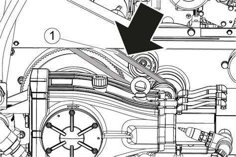
Use your thumb to depress the V-belt of the engine. When exerting a force of 100 N, the V-belt should sag 7...10 mm.
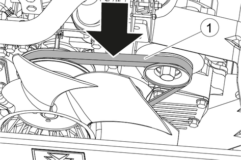
If the V-belt of the engine sags any more than this, the tension of the V-belt must be increased.
Check the V-belt for cracks, traces of oil and wear. If the V-belt touches the bottom of the pulley, it means the V-belt is worn.
If the V-belt is damaged, fouled with oil or worn, replace the V-belt.
Loosen the locking screw.
Use a rod to push the generator away from the engine block and tighten the locking screw.
Check the tension of the engine V-belt.
If necessary, repeat the process until the tension of the belt is correct.
Replace the old V-belt of the engine with a new V-belt.
Adjust the tension of the engine V-belt in such a way that it sags 5...8 mm when subjected to a force of 100 N.
Operate the device for 5 minutes.
The engine V-belt must then sag 7...10 mm when subjected to a force of 100 N. If not, adjust the tension of the belt again.
Stop the engine and let it cool down.
Turn the fuel cock to the “OFF” position.
Unscrew the fuel filter in a counter-clockwise direction by using a filter wrench.
Wet the seal of the new fuel filter with diesel fuel.
Screw in the new fuel filter clockwise by hand until it rests against the contact surface.
Use a filter wrench to tighten the new fuel filter to 20...23 Nm or turn it 1 more revolution after coming into contact with the contact surface.
Turn the fuel cock to the “ON” position.
To vent the fuel system, turn the engine switch to position “1”.
Wait 15 seconds.
Check the fuel filter for fuel leaks.
Position the device on a level surface.
Start and operate the device until the engine is at operating temperature.
Shut down the engine.
Danger of burns
Hot engine parts cause burns on contact.
When changing the oil, keep your hands and other parts of your body away from the hot parts of the engine. Do not open the radiator cap under any circumstances.
Remove the oil cap.
Place a catch pan underneath the oil drain screw to collect the engine oil.
Danger of burns
Hot engine oil causes burns.
Avoid contact with hot engine oil. Wear suitable protective clothing and eye protection.
Unscrew the oil drain screw and allow the engine oil to drain.
Screw in and tighten the oil drain screw (54...64 Nm).
Unscrew the oil filter in a counter-clockwise direction by using a filter wrench.
Clean the connecting parts of the new oil filter.
Lightly coat the sealing ring of the new oil filter with engine oil.
Screw in the new oil filter clockwise by hand until it rests against the contact surface.
Use a filter wrench to tighten the new oil filter to 20...23 Nm or turn it 1 more revolution after coming into contact with the contact surface.
Risk of damage
If contaminated or incorrect oil is used, it can damage the engine and reduce its service life.
Only use the specified type of oil (see “Technical data”). Make sure the engine oil is not contaminated with any particles. Thoroughly clean the oil cap and dipstick and the surrounding areas. Do not mix different types of oil. Do not exceed the maximum oil level.
Fill in new engine oil via the engine oil filling hole (for the oil type and quantity, see “Technical data”).
Wait 3 minutes.
Check the oil level.
Top up the oil if necessary.
Attach and hand-tighten the oil cap.
Start up the device and let the engine warm up for 5 minutes, then check for oil leaks.
Shut down the engine.
Wait 10 minutes.
Check the oil level
Correct the oil level if necessary.
Turn the key-operated switch to position “0”.
Release the locking elements.

Remove the cover of the air filter casing.
Remove the filter element.
Blow compressed air through the filter element from the inside (2.9...4.9 bar).
Note: Start with the lowest pressure. Only increase the pressure if the cleaning effect is insufficient.
Wipe the inside of the air filter casing.
Replace the filter element if one of the following conditions is fulfilled:
The engine performance decreases.
The filter element is heavily contaminated.
The filter element is fouled with oil.
Insert the filter element into the air filter casing.
Place the cover on the air filter casing. When doing this, align the arrows on the cover and the casing.
The locking elements engage in place.
Follow the same procedure used for “Cleaning the air filter element”.
Replace the filter element with a new filter element instead of cleaning it.
Have all checks and work on electrical parts performed by an expert.
In case of any malfunctions not mentioned in this chapter, contact the authorised Customer Service.
The device can start unintentionally.
The high-pressure water jet or impelled parts can cause injuries.
Set the power switch to 0/OFF and actuate the trigger of the high-pressure gun until the device is depressurised before eliminating a malfunction.
The water shortage indicator lamp lights up
Remedy:
Check the water inlet pressure and the water volume.
Check the water filter for contamination.
In the Advanced version, check the float valves in the float container.
In the Advanced version, check the V-belt of the advance pressure pump for:
Condition
Belt tension
The low fuel indicator lamp lights up
Remedy:
When the indicator light first lights up, one third of the tank content is still available as a reserve. The reserve is sufficient for about 2 hours of full-load operation.
If necessary, refill the fuel tank.
The “charge battery” indicator lamp lights up
Remedy:
Check the V-belt of the engine for:
Condition
Belt tension
Check the condition of the battery.
Have the generator checked by the Yanmar service team.
Only EU version devices are equipped with a display.
A current error message is shown immediately in the display.
An error message containing further information about the fault can be called up by pressing the CONFIRM button.
The error messages that have occurred can be displayed by using the “Fault Codes” function.
Press the MAIN MENU button.
Select the submenu “Fault Codes” by pressing the NEXT button.
The list of error messages is displayed.
Use the DOWN and UP buttons to select an error message.
Use the “?” button to call up detailed information about this error message.
The device does not run
Remedy:
Check the indicator lamps.
Check the condition of the battery.
Device does not reach required pressure
Remedy:
Check the size of the nozzle.
Clean the nozzle and replace if necessary.
Replace the filter insert.
Unscrew the filter casing.
Renew the filter insert.
Close the filter casing.
Vent the device (see chapter "Venting the device").
Check the water supply line to the pump for leaks or blockages.
Contact Customer Service if necessary.
Leak at the high-pressure hose
Remedy:
Turn the trigger to "0/OFF".
Discharge the pressure by opening the high-pressure gun.
Re-tighten the hose screw connections.
Replace the O-rings.
If the hose leaks (at the hose surface, at the pressure relief hole) then stop using the high-pressure hose immediately and do not use it again.
The high-pressure pump knocks
Remedy:
Check the water supply line to the pump for leaks or blockages.
Vent the device (see chapter "Venting the device").
Internal combustion engine | |
Engine type | Yanmar 4TNV88 |
Type | Diesel, 4-stroke |
Engine capacity | 2,190 l |
Cylinder | 4 |
Power | 35,5 / 48,2 kW/PS |
Specific consumption | ~9,5 l/h |
Engine speed | 3100 1/min |
Exhaust emissions standard | Stage 3a |
Battery | |
Working voltage of the battery | 12 V |
Battery capacity | 95 Ah |
Length x width x height | 353x175x190 mm |
Water connection | |
Feed pressure | 0,1-0,5 MPa |
Input temperature (max.) | 45 °C |
Input amount (min.) | 22,5 l/min |
Minimum water supply hose length | 7,5 m |
Minimum water supply hose diameter | 1 in |
Device performance data | |
Nozzle size of standard nozzle | 1,00 (type F19) mm |
Operating pressure | 100 MPa |
Operating pressure (max.) | 110 MPa |
Water flow rate | 14,6 l/min |
High-pressure gun recoil force | 122 N |
Permissible temperature range | +5...+40 °C |
Operating materials | |
Fuel type | Diesel |
Fuel tank capacity | 49 l |
Motor oil type | SAE 15 W40 |
Engine oil volume | 7,4 l |
Amount of coolant | 2,7 l |
Pump oil type | 15W40 |
Pump oil volume | 5,5 l |
Dimensions and weights | |
Typical operating weight | 650 kg |
Length | 1710 mm |
Width | 960 mm |
Height | 1310 mm |
Determined values in acc. with EN 60335-2-79 | |
Hand-arm vibration value for nozzle F19/F4, turbo nozzle TD 3000 | <2,5 m/s2 |
Hand-arm vibration value for Orbimaster nozzle | 3,5 m/s2 |
Uncertainty K | 0,8 m/s2 |
Sound pressure level | 91 dB(A) |
Uncertainty KpA | 4 dB(A) |
Sound power level LWA + K uncertaintyWA | 111 dB(A) |
Internal combustion engine | |
Engine type | Yanmar 4TNV88 |
Type | Diesel, 4-stroke |
Engine capacity | 2,190 l |
Cylinder | 4 |
Power | 35,5 / 48,2 kW/PS |
Specific consumption | ~9 l/h |
Engine speed | 3100 1/min |
Exhaust emissions standard | Stage 5 |
Battery | |
Working voltage of the battery | 12 V |
Battery capacity | 95 Ah |
Length x width x height | 353x175x190 mm |
Water connection | |
Feed pressure | 0,1-0,5 MPa |
Input temperature (max.) | 45 °C |
Input amount (min.) | 22,5 l/min |
Minimum water supply hose length | 7,5 m |
Minimum water supply hose diameter | 1 in |
Device performance data | |
Nozzle size of standard nozzle | 1,00 (type F19) mm |
Operating pressure | 100 MPa |
Operating pressure (max.) | 110 MPa |
Water flow rate | 14,6 l/min |
High-pressure gun recoil force | 122 N |
Permissible temperature range | +5...+40 °C |
Operating materials | |
Fuel type | Diesel |
Fuel tank capacity | 49 l |
Motor oil type | SAE 15 W40 |
Engine oil volume | 7,4 l |
Amount of coolant | 2,7 l |
Pump oil type | 15W40 |
Pump oil volume | 5,5 l |
Dimensions and weights | |
Typical operating weight | 650 kg |
Length | 1710 mm |
Width | 960 mm |
Height | 1310 mm |
Determined values in acc. with EN 60335-2-79 | |
Hand-arm vibration value for nozzle F19/F4, turbo nozzle TD 3000 | <2,5 m/s2 |
Hand-arm vibration value for Orbimaster nozzle | 3,5 m/s2 |
Uncertainty K | 0,8 m/s2 |
Sound pressure level | 91 dB(A) |
Uncertainty KpA | 4 dB(A) |
Sound power level LWA + K uncertaintyWA | 111 dB(A) |
Internal combustion engine | |
Engine type | Yanmar 4TNV88 |
Type | Diesel, 4-stroke |
Engine capacity | 2,190 l |
Cylinder | 4 |
Power | 35,5 / 48,2 kW/PS |
Specific consumption | ~9,5 l/h |
Engine speed | 3100 1/min |
Exhaust emissions standard | Stage 3a |
Battery | |
Working voltage of the battery | 12 V |
Battery capacity | 95 Ah |
Length x width x height | 353x175x190 mm |
Water connection | |
Feed pressure | 0,1-0,6 MPa |
Input temperature (max.) | 45 °C |
Input amount (min.) | 22,5 l/min |
Minimum water supply hose length | 7,5 m |
Minimum water supply hose diameter | 1 in |
Device performance data | |
Nozzle size of standard nozzle | 1,00 (type F19) mm |
Operating pressure | 100 MPa |
Operating pressure (max.) | 110 MPa |
Water flow rate | 14,6 l/min |
High-pressure gun recoil force | 122 N |
Permissible temperature range | +5...+40 °C |
Operating materials | |
Fuel type | Diesel |
Fuel tank capacity | 49 l |
Motor oil type | SAE 15 W40 |
Engine oil volume | 7,4 l |
Amount of coolant | 2,7 l |
Pump oil type | 15W40 |
Pump oil volume | 5,5 l |
Dimensions and weights | |
Typical operating weight | 675 kg |
Length | 1710 mm |
Width | 960 mm |
Height | 1310 mm |
Determined values in acc. with EN 60335-2-79 | |
Hand-arm vibration value for nozzle F19/F4, turbo nozzle TD 3000 | <2,5 m/s2 |
Hand-arm vibration value for Orbimaster nozzle | 3,5 m/s2 |
Uncertainty K | 0,8 m/s2 |
Sound pressure level | 91 dB(A) |
Uncertainty KpA | 4 dB(A) |
Sound power level LWA + K uncertaintyWA | 111 dB(A) |
Internal combustion engine | |
Engine type | Yanmar 4TNV88 |
Type | Diesel, 4-stroke |
Engine capacity | 2,190 l |
Cylinder | 4 |
Power | 35,5 / 48,2 kW/PS |
Specific consumption | ~9 l/h |
Engine speed | 3100 1/min |
Exhaust emissions standard | Stage 5 |
Battery | |
Working voltage of the battery | 12 V |
Battery capacity | 95 Ah |
Length x width x height | 353x175x190 mm |
Water connection | |
Feed pressure | 0,1-0,6 MPa |
Input temperature (max.) | 45 °C |
Input amount (min.) | 22,5 l/min |
Minimum water supply hose length | 7,5 m |
Minimum water supply hose diameter | 1 in |
Device performance data | |
Nozzle size of standard nozzle | 1,00 (type F19) mm |
Operating pressure | 100 MPa |
Operating pressure (max.) | 110 MPa |
Water flow rate | 14,6 l/min |
High-pressure gun recoil force | 122 N |
Permissible temperature range | +5...+40 °C |
Operating materials | |
Fuel type | Diesel |
Fuel tank capacity | 49 l |
Motor oil type | SAE 15 W40 |
Engine oil volume | 7,4 l |
Amount of coolant | 2,7 l |
Pump oil type | 15W40 |
Pump oil volume | 5,5 l |
Dimensions and weights | |
Typical operating weight | 675 kg |
Length | 1710 mm |
Width | 960 mm |
Height | 1310 mm |
Determined values in acc. with EN 60335-2-79 | |
Hand-arm vibration value for nozzle F19/F4, turbo nozzle TD 3000 | <2,5 m/s2 |
Hand-arm vibration value for Orbimaster nozzle | 3,5 m/s2 |
Uncertainty K | 0,8 m/s2 |
Sound pressure level | 91 dB(A) |
Uncertainty KpA | 4 dB(A) |
Sound power level LWA + K uncertaintyWA | 111 dB(A) |
The warranty conditions issued by our relevant sales company apply in all countries. We shall remedy possible malfunctions on your appliance within the warranty period free of cost, provided that a material or manufacturing defect is the cause. In a warranty case, please contact your dealer (with the purchase receipt) or the next authorised customer service site.
(See overleaf for the address)
EU Declaration of Conformity |
We hereby declare that the machine described below complies with the relevant basic safety and health requirements in the EU Directives, both in its basic design and construction as well as in the version placed in circulation by us. This declaration is invalidated by any changes made to the machine that are not approved by us.
Product: High-pressure cleaner
Type: 1.367-xxx
Currently applicable EU Directives2000/14/EC
2006/42/EC (+2009/127/EC)
2011/65/EU
2014/30/EU
Harmonised standards usedEN 55012: 2007 + A1: 2009
EN 55014-2: 2015
EN 62233: 2008
EN IEC 63000: 2018
EN 1829-1
EN 1829-2
Applied conformity evaluation method2000/14/EG: Annex V
Sound power level dB(A)Measured: 107
Guaranteed: 111
The signatories act on behalf of and with the authority of the company management.

Documentation supervisor:
S. Reiser
Alfred Kärcher SE & Co. KG
Alfred-Kärcher-Str. 28 - 40
71364 Winnenden (Germany)
Ph.: +49 7195 14-0
Fax: +49 7195 14-2212
Winnenden, 2021/05/01
Declaration of Conformity (UK) |
We hereby declare that the product described below complies with the relevant provisions of the following UK Regulations, both in its basic design and construction as well as in the version put into circulation by us. This declaration shall cease to be valid if the product is modified without our prior approval.
Product: High-pressure cleaner
Type: 1.367-xxx
Currently applicable UK RegulationsS.I. 2001/1701 (as amended)
S.I. 2008/1597 (as amended)
S.I. 2012/3032 (as amended)
S.I. 2016/1091 (as amended)
Designated standards usedEN 55012: 2007 + A1: 2009
EN 55014-2: 2015
EN 62233: 2008
EN IEC 63000: 2018
EN 1829-1
EN 1829-2
Applied conformity assessment procedureS.I. 2001/1701 (as amended): Schedule 8
Sound power level dB(A)Measured: 107
Guaranteed: 111
The signatories act on behalf of and with the authority of the company management.
Documentation supervisor:
S. Reiser
Alfred Kärcher SE & Co. KG
Alfred-Kärcher-Str. 28 - 40
71364 Winnenden (Germany)
Ph.: +49 7195 14-0
Fax: +49 7195 14-2212
Winnenden, 2021/05/01

4-2-SC-A4-GS-17339