MC 250Implements
59692240 (01/22)
59692240 (01/22)
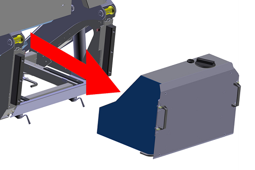
The waste container attachment can only be used in conjunction with a Kärcher brush sweeping system or scrubbing system. These attachments are described after the chapter.
The waste container can only be removed and set down when the support attachment kit (optional) is used. The description assumes the use of the support attachment kit.
Risk of injury from the waste container
Keep a sufficient distance from the waste container and the supports when removing/installing.
Maintain a sufficient clearance to the hazard zone and stop raising/lowering of the waste container immediately when a person enters the hazard zone.
Secure the raised waste container with the safety supports when you work underneath.
Only remove the waste container when it is completely empty.
Risk of injury and damage
Set the waste container down only on a level and smooth surface.
Empty the waste container before removing the waste container. See chapter "Emptying the waste container".

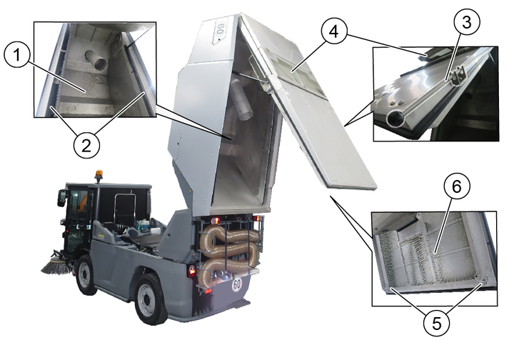
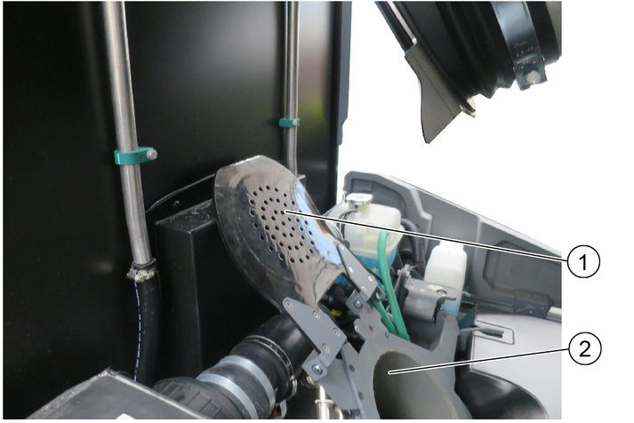
Figure: Waste container secured
Raise the waste container until the safety supports can be folded forward. See chapter "Emptying the waste container".
Lower the waste container onto the safety supports.

Remove the sealing collar by opening the hose clip (SW 7) and pulling off the sealing collar.
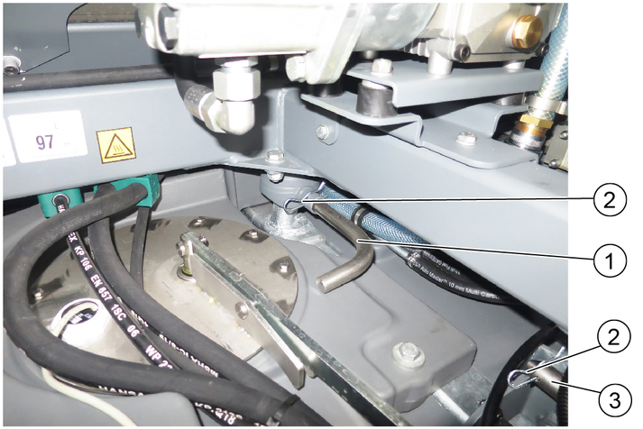
Figure: Variant A with 2 short locking pins
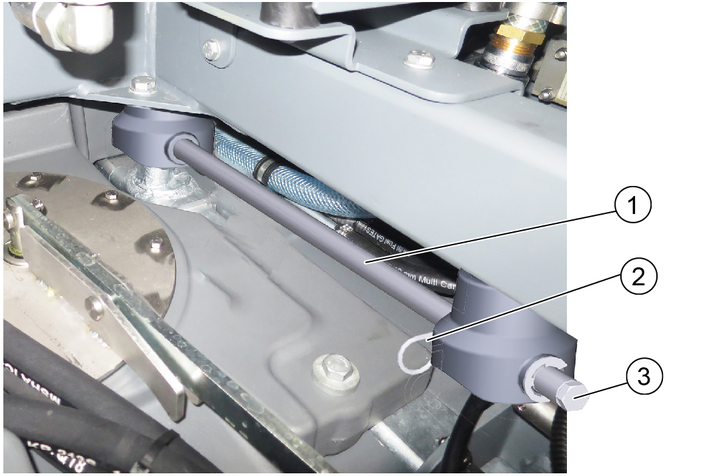
Figure: Variant B with long locking pin
Variant A: First pull out the spring pins and then pull out the front short locking pins (left and right).
Variant B: First pull out the spring pins and then completely pull out the long locking pins (left and right).
Use an impact extractor (slide hammer) for pulling out
For this, unscrew the hexagon bolt and screw the slide hammer into the existing thread.
Raise the waste container slightly and fold the safety supports to the rear and into the storage position.
Lower the waste container completely.
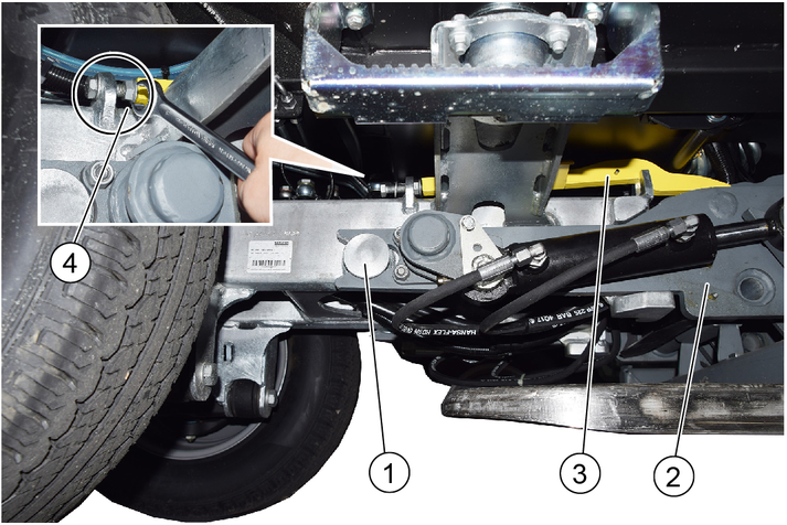
Depressurise the rear hydraulic system, see chapter "Hydraulic pressure relief".
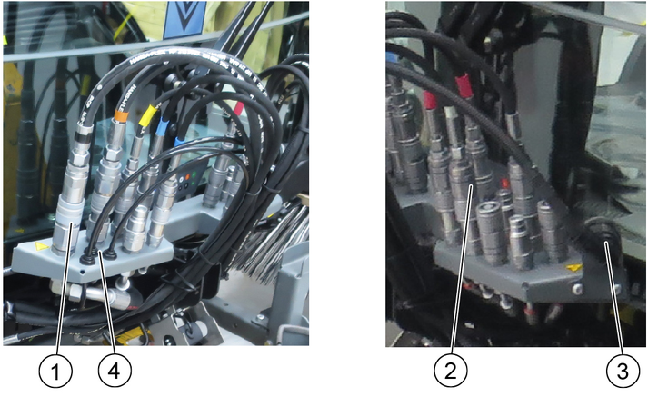
Disconnect the hydraulic hoses of the waste container from the hydraulic connections.
Unplug the power supply plug.
Disconnect the reversing camera cable (if present).
With optional high-pressure cleaner: Disconnect the water connection.
Pivot the side covers (left and right) outwards.
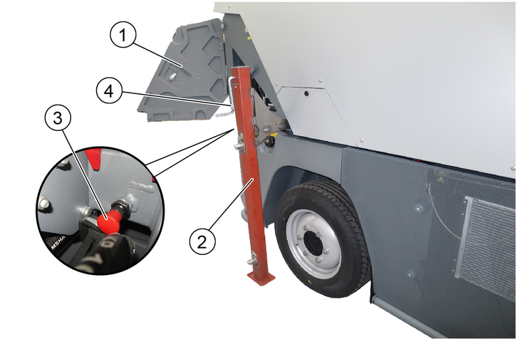
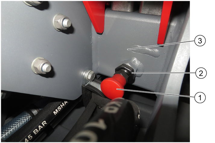
Figure: Attached locking button with inserted and secured support
Caution: Before the supports are pushed in, all 4 locking buttons (scope of delivery of the "Supports" attachment kit) must be attached to the left front and rear as well as right front and rear of the waste container, adjusted and secured with the lock nuts. See "Installing the locking buttons" at the end of this chapter .
Push in the rear supports (left and right) all the way to the end stop while pulling out the red retaining head. Release the locking button to lock. The locking pin engages in the holes in the supports when locking. Check that the supports are locked securely.
Attach and secure the front supports as already described for the rear supports.
The front supports are marked and only fit on the corresponding side.

Figure: Variant A with 2 short locking pins
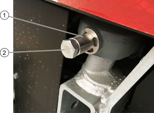
Figure: Variant B with long locking pin
With variant A: Crank up the rear supports until the locking pins at the rear can be pulled out.
To pull out the spring pin, first open the tailgate of the waste container. The tailgate is available in 2 different versions.
Variant 1: The tailgate can be opened with a square key.
Variant 2: The tailgate is a screwed sheet metal part, either remove the 4 screws or pull out the spring cotter pin through the side opening.
Pull out the spring pin.
Pull out the short locking pins (left and right).
With variant B: Check that the long locking pin has already been pulled out completely, if so, no further action is necessary.
Alternately crank up the supports at the front and rear (left and right):
Until the waste container is free above the ball sockets.
Until the recycling water valve is exposed.
Make sure that the front of the waste container does not press against the cab.
The waste container now stands free on the supports.
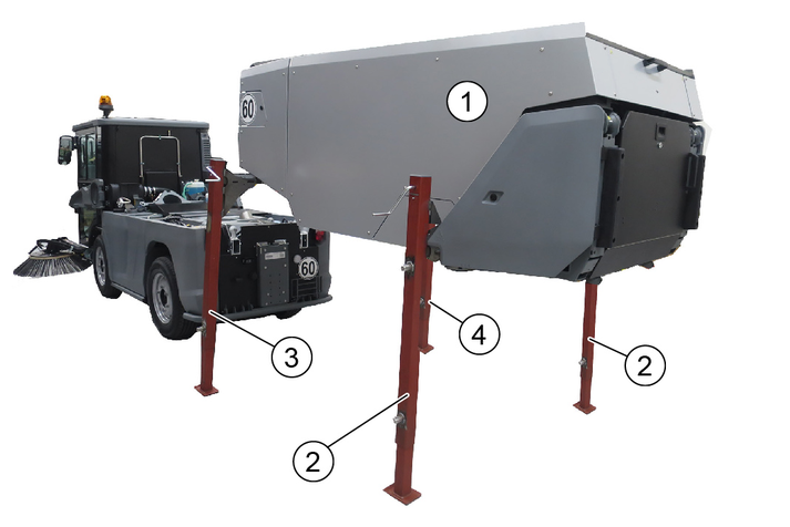
Symbolic illustration: Waste container on supports
Supports are identical
Support is marked for left
Support is marked for right
Drive the rear of the vehicle carefully out from under the waste container.
Mounting the locking buttons (4x)
The locking buttons 6.321-295.0 are part of the "Supports" attachment kit
Screw the locking button into the thread of the welded nut on the frame and adjust:
If the setting is correct, the bolt of the pulled locking button releases the slot for the supports.
Secure with counternut.
Risk of injury from the waste container
Keep a sufficient distance from the waste container and the supports when removing/installing.
Maintain a sufficient clearance to the hazard zone and stop raising/lowering of the waste container immediately when a person enters the hazard zone.
Secure the raised waste container with the safety supports when you work underneath.
Risk of injury and damage
Set the waste container down only on a level and smooth surface.
Check the correct seating of ball sockets and locking pins when installing.
If necessary, use the assistance of a second person (guide) when attaching the waste container.
Figure: Waste container on supports
The waste container is attached to the vehicle in the reverse order to removal, which is why the pictorial representation is omitted here.
Drive the vehicle carefully under the waste container.
The side panels on the left and right must be open.
Lower the waste container by cranking the supports until the waste container lies securely in the 4 ball sockets. Use the assistance of a second person if necessary.
Pull the locking button and release the lock of the supports, pull out the supports (4x).
Insert the rear locking pins (left and right) and secure with spring pins.
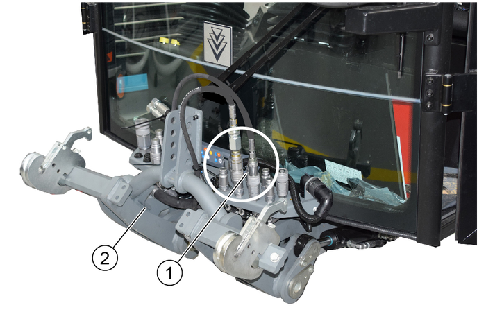
Depressurise the rear hydraulic system, see chapter "Hydraulic pressure relief".
Connect the hydraulic hoses of the waste container (note the colours).
Connect the power supply plug.
With optional high-pressure cleaner: Connect the water connection.
Raise the waste container and secure it with the safety supports.
Fit the sealing collar.
Insert the front locking pins (left and right) and secure with spring pins.
Lower the waste container completely. Fold in the safety supports beforehand.
The waste container is now attached to the vehicle.
Select the appropriate > Sweep < program on the display.
Risk of tilting
Only empty the waste container on a firm even subsurface.
Maintain the safety distance while emptying on dumps or ramps.
Danger due to rolling away
Set the travel direction lever to neutral for emptying.
Apply parking brake.
Danger of injury
Switch off the suction fan before emptying the waste container.
Risk of injury
During the emptying process, persons and animals must not abide within the swivelling range of the waste container.
Crush hazard
Never reach into the rod assembly for the emptying mechanism.
Risk of fire
When emptying, make sure that no flammable material (e.g. leaves ... ) is present in the emptying area.
If a manual suction hose attachment kit is attached to the vehicle, fold it to the side and secure it before emptying. See chapter “Manual suction hose attachment”.
Drive the vehicle to the emptying position in slow transport mode.
Stop the vehicle.
Bring the travel direction lever into the neutral position (middle position).
Switch on the hydraulic system (PTO).
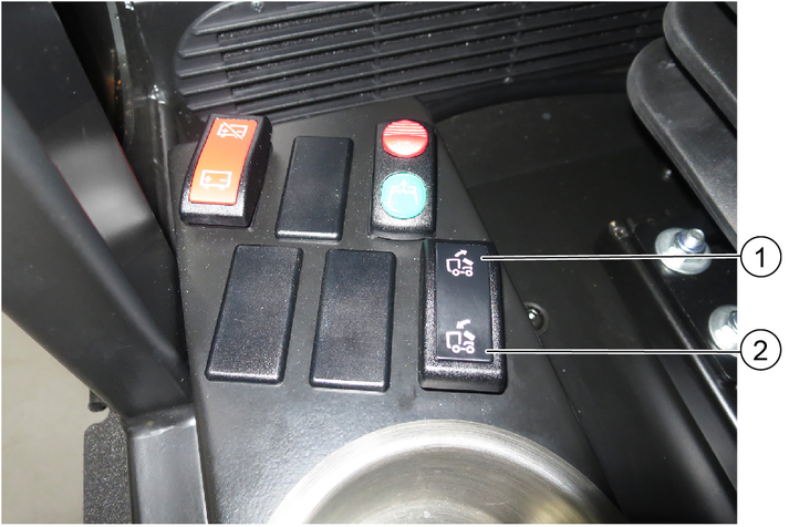
Operate the switch.
Empty the waste container.
Note
Always raise the waste container fully to the end position.
If necessary, remove any adhering soiling with a dirt scraper (optional) and clean with water. See chapter "Cleaning the waste container"
Waste container volume (gross) | l (m3) | 2500 (2.5) |
We hereby declare that the machine described below complies with the relevant basic safety and health requirements in the EU Directives, both in its basic design and construction as well as in the version placed in circulation by us. This declaration is invalidated by any changes made to the machine that are not approved by us.
Product: Sweeper
Type: PF-E (MC 250)
Currently applicable EU Directives2006/42/EC (+2009/127/EC)
2014/30/EU
2000/14/EC
Harmonised standards usedEN 13019
CISPR 12
Applied conformity evaluation method2000/14/EG: Annex V
Sound power level dB(A)MC 250 Euro 6
Measured: 106
Guaranteed: 108 99 *with optional sound proofing attachment kit (ex-factory)
MC 250 Level V
Measured: 105
Guaranteed: 108 99 *with optional sound proofing attachment kit (ex-factory)
The undersigned act on behalf and under the power of attorney of the company management.

Documentation supervisor:
S. Reiser
Alfred Kärcher SE & Co. KG
Alfred-Kärcher-Str. 28 - 40
71364 Winnenden (Germany)
Ph.: +49 7195 14-0
Fax: +49 7195 14-2212
Winnenden, 2020/01/01
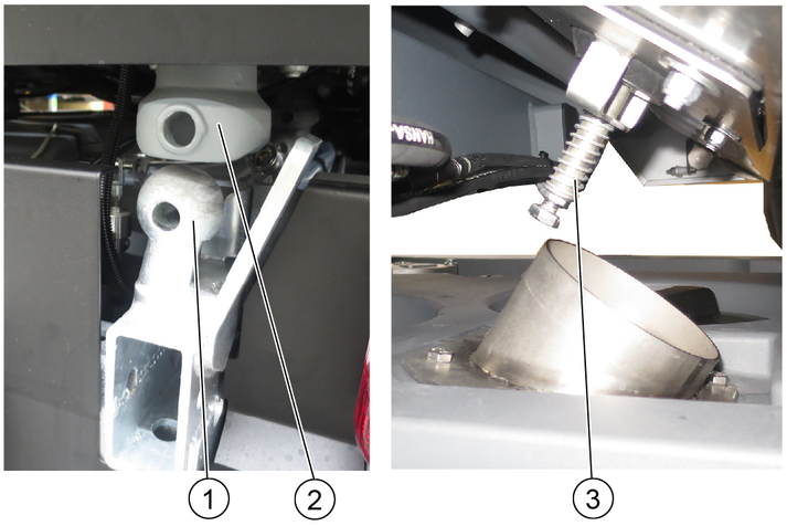
The emergency operation is required for the following activities:
Raise lower the waste container if the device's hydraulics have failed, e.g. due to a failure of the engine.
With the engine switched off: Turn the knurled screw into the appropriate position, the waste container can be raised or lowered.
Operate the manual pump with the hand tube located in the box under the passenger seat.
Before starting work in the engine compartment, secure the raised waste container with the red safety supports (on the lifting cylinders) on the left and right.
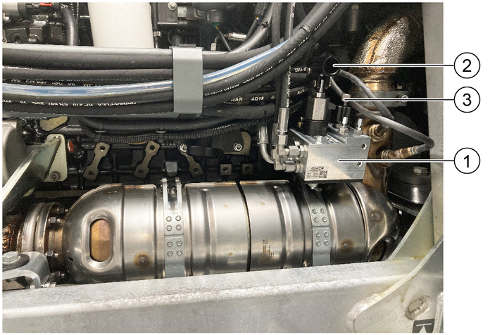
The emergency lift pump can be used to manually raise or lower the waste container or grit container when the engine is switched off.
The emergency lift pump is accessible after swinging open the fresh water tank and is operated with a plug-in hand lever.
Do not operate the emergency lift pump while the engine is running!
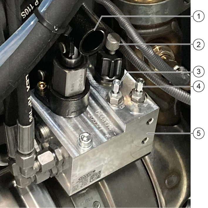
To lift or lower the waste container or grit container, set the knurled screw and the function screws A and B to one of the following positions:
Home position:
Knurled screw: screwed in
Function screw A: screwed in
Function screw B: screwed in
Lift container:
Knurled screw: screwed out
Function screw A: screwed out
Function screw B: screwed in
Lower the container in front of the upper tipping point:
Knurled screw: screwed out
Function screw A: screwed out
Function screw B: screwed in
Lower the container from the rear end position:
Knurled screw: screwed out
Function screw A: screwed out
Function screw B: screwed out
Release the counternuts on the function screws A and B.
Manually turn the knurled screw and the function screws A and B to the required position.
Insert the hand lever into the hand lever mount and operate it several times until the waste container or grit container is raised or lowered.
Finally, turn the knurled screw and the function screws A and B to the home position.
Tighten the counternuts of the function screws A and B.
Remove the pump lever and stow it in the storage compartment under the passenger seat together with the hexagonal key.
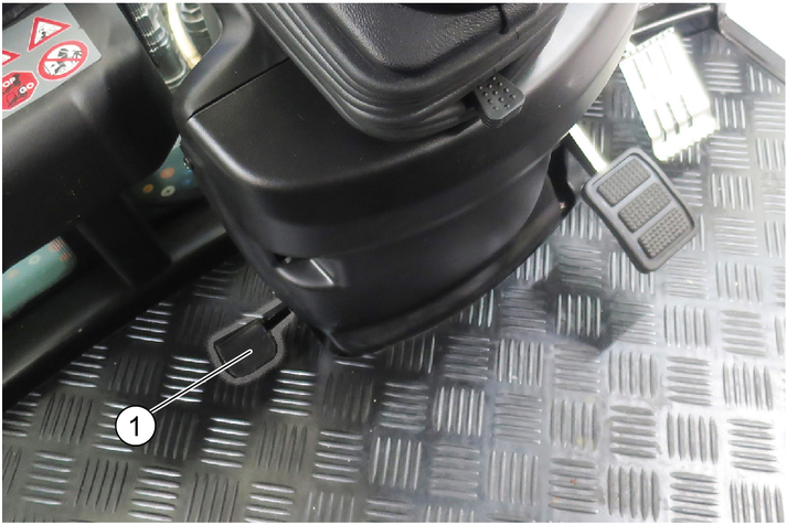
The lock secures the attachments (e.g. sweeping system, front power lift). It is located on the left and right-hand side in front of the front wheel and can be identified as a yellow lever.
Danger of accident
Check the locking mechanism for correct adjustment with each attachment.
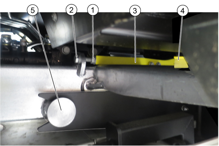
Opening the lock
Unscrew the counternut.
Loosen the screw from the left and right-hand locking lever by approx. 1 cm. The lock is released.
Lift the locking lever via the side handle, then push it backwards. The attachment can be removed.
Closing the lock
Insert the mounting arm of the attachment as far as its stop.
Push the locking lever forwards.
Tighten the screw; check to ensure the attachment is fixed securely in place.
Tighten the lock nuts.
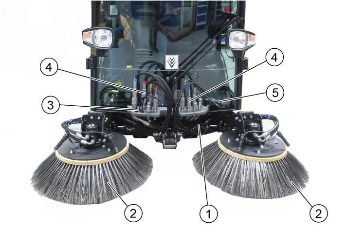
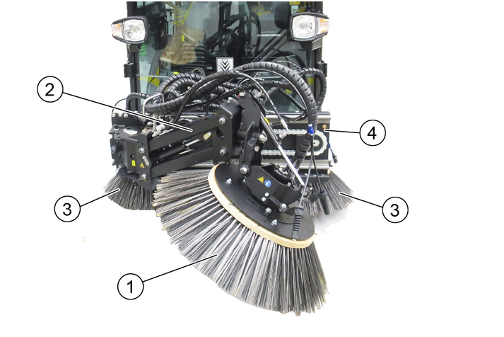
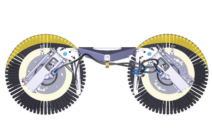
Figure: Sweeping system attached
A changing carriage is required for removing/attaching the sweeping system.
Optional accessory, order no. 2.852-862.0
Park the vehicle on a level surface.
The brush system must be sitting on the changing carriage for removal/installation from/on the vehicle. Use a lift truck for removal/installation.
The corresponding > Sweep < program must be selected on the display.
The removal of the sweeping system is described with the optionally available changing carriage.
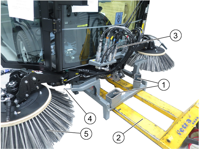
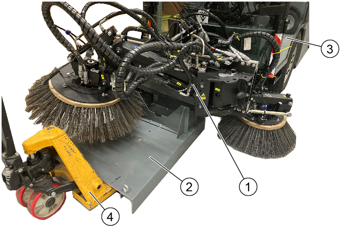
Figure: Sweeping system with changing carriage
Stop the vehicle on level, solid ground and secure it against rolling away.
Move the changing carriage into position under the vehicle using the lift truck.
Move the side brushes individually into the side brush holder and lower into the correct position.
Depressurise the front hydraulics. See chapter "Depressurising the hydraulic system".
Pull off the hydraulic hoses, water connections and power supply connection and store them in the holder on the changing carriage.
Release the suction hose at the suction mouth (hose clip).
Open the locks (left and right). See chapter "Opening/closing the lock".
Extend the changing carriage with sweeping system with suction mouth.
Raise and secure the waste container.

Release the lock on the holder.
Release both water connections.
Pull out the holder with the attached suction hose upwards.
Store the sweeping system in a safe and dry place.
Attachment of the sweeping system is described using the optionally available changing carriage. The corresponding >Sweep< program must be selected on the display.
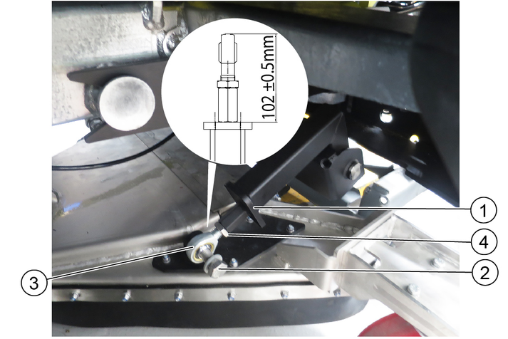
When installing the suction mouth for the first time, attach the suction nozzle to the sweeping system by attaching the carrier connection to the suction mouth (left/right) and adjusting it (102 ± 0.5mm).
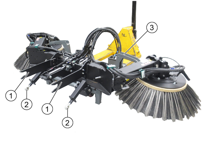
Figure: Sweeping system with changing carriage (shown without suction mouth)
The sweeping system is attached to the vehicle in the reverse order to removal, which is why some of the illustrations are omitted here.
Stop the vehicle on level, solid ground and secure it against rolling away.
Select the appropriate > Sweep < program on the display.
Open the locks (left and right). See chapter "Opening/closing the lock".
Use a pallet truck to position the changing carriage carrying the sweeping system on it and suction mouth at the vehicle.
Move the fastening arms (left/right) into the mount provided on the vehicle as far as they will go. Check for correct seating before locking.
Close the lock (screw) to fix the attachment in place.
Raise and secure the waste container.
Route both water connections upwards.
Guide the holder with the attached suction hose down to the suction mouth and lock in place.
Fit the suction hose to the suction mouth (hose clip).
Depressurise the front hydraulics. See chapter "Depressurising the hydraulic system".
Connect the hydraulic hoses, noting the connection colours of the hydraulic hoses.
Connect (plug in) water hoses.
Insert the plug of the brush system electrical connection into the power supply.
Individually raise and extend the side brushes.
Move the changing carriage out of the way.
Lower the waste container completely.
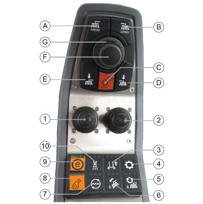
The indicators in the switches light when the switches are switched on.
Joystick forwards: Lower both brush arms and switch the sweeping brush on
Joystick backwards: Raise both brush arms and switch off the sweeping brush
Joystick to the left/right: Pivot the left brush arm
Joystick forwards: Lower the left brush arm and switch the sweeping brush on
Joystick backwards: Raise the left brush arm and switch off the sweeping brush
Joystick to the left/right: Pivot the left brush arm
Joystick forwards: Lower both brush arms and switch the sweeping brush on
Joystick backwards: Raise both brush arms and switch off the sweeping brush
Joystick to the left/right: Pivot the right brush arm
Joystick forwards: Lower the right brush arm and switch the sweeping brush on
Joystick backwards: Raise the right brush arm and switch off the sweeping brush
Joystick to the left/right: Pivot the right brush arm
Press the button for longer than 2 seconds, the suction mouth is in the floating position
The inclination is then adjusted with the right joystick
Press for longer than 2 seconds, dosage of recycling water adjustable
(A) | Sweeping brush speed selection, common for the left-hand and right-hand sides |
(B) | Button is not used |
(C) | Engine speed Press to adjust the values NoteThe suction performance depends on the set engine speed.
|
(D) | Not used |
(E) | Left-hand and right-hand side brush pressure relief button |
(F) | Save button Press to save adjusted values or programs |
(G) | Rotary knob Press to change the adjusted values |
The existing lubrication points (grease nipples) are labelled.
Lubricate daily with multi-purpose grease.
Check the sweeping brushes for tangled cords and straps and remove as necessary.
Keep the hydraulic connections clean and check for leaks once a week.
Check the sweeping brushes for wear and damage and replace if necessary.
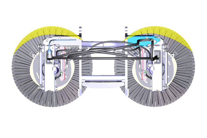
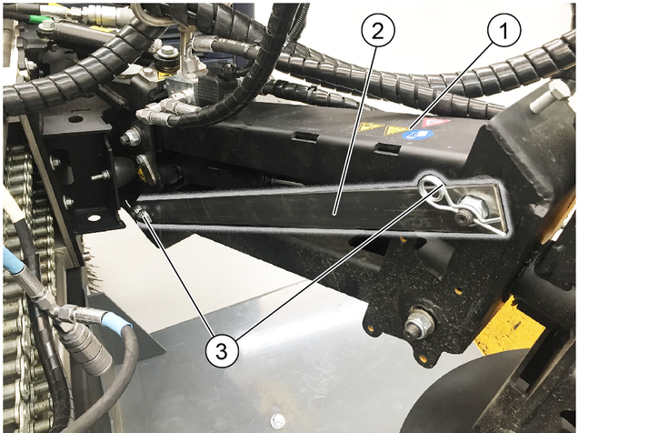
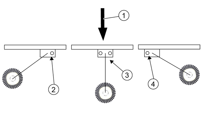
Adjust the sweeping area as shown in the illustration.
Right: 9 am- 2 pm
Right-hand side: 10 am- 3 pm
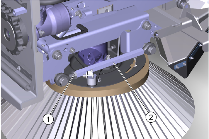
Adjusting the side inclination
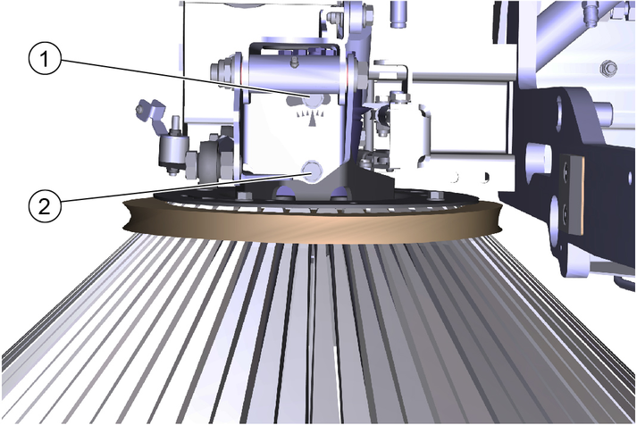
Unscrew the screws.
Adjust the side inclination via the rotation point of screw 1.
Tighten the screws.
Adjusting the head inclination forwards
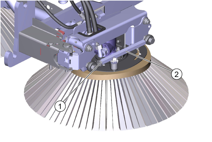
Unscrew the counternut.
Adjusting the head inclination via the hexagon.
Tighten the counternut.
Adjusting the brush contact pressure
The brush system has a hydraulic brush contact pressure relief system.
Risk of injury and damage
Note the weight of the device.
Risk of damage
Store the attachment kit in a protected, level and dry place. Ensure that the sweeping brushes are not loaded.
Store the sweeping system that has been removed from the vehicle on the changing carriage.
Ensure that the sweeping brushes are not loaded during attachment to the vehicle.
A changing carriage is required for removing/attaching the sweeping system.
Optional accessory, order no. 2.852-862.0
Park the vehicle on a level surface.
The brush system must be sitting on the changing carriage for removal/installation from/on the vehicle. Use a lift truck for removal/installation.
The corresponding > Sweep < program must be selected on the display.
Remove the 3-brush sweeping system with the optionally available changing carriage.
Stop the vehicle on level, solid ground and secure it against rolling away.
Move the changing carriage into position under the vehicle using the lift truck.
Move the side brushes individually into the side brush holder and lower into the correct position.
Secure the brush arm for the front brush with a locking plate and retaining clip.
Secure the front brush with a locking plate.
Depressurise the front hydraulics. See chapter "Depressurising the hydraulic system".
Pull off the hydraulic hoses, water connections and power supply connection and store them in the holder on the changing carriage.
Release the suction hose at the suction mouth (hose clip).
Open the locks (left and right). See chapter "Opening/closing the lock".
Extend the 3-brush sweeping system.
Raise and secure the waste container.
Release the lock on the holder.
Release both water connections.
Pull out the holder with the attached suction hose upwards.
Store the sweeping system in a safe and dry place.
Attach the sweeping system using the optionally available changing carriage. The corresponding >Sweep< program must be selected on the vehicle display.
When installing the suction mouth for the first time, attach the suction nozzle to the sweeping system by attaching the carrier connection to the suction mouth (left/right) and adjusting it (102 ± 0.5mm).
Stop the vehicle on level, solid ground and secure it against rolling away.
Select the appropriate >Sweep< program on the vehicle display.
Open the locks (left and right). See chapter "Opening/closing the lock".
Use a pallet truck to position the changing carriage carrying the sweeping system on it and suction mouth at the vehicle.
Move the fastening arms (left/right) into the mount provided on the vehicle as far as they will go. Check for correct seating before locking.
Close the lock (screw) to fix the attachment in place.
Raise and secure the waste container.
Route both water connections upwards.
Guide the holder with the attached suction hose down to the suction mouth and lock in place.
Fit the suction hose to the suction mouth (hose clip).
Depressurise the front hydraulics. See chapter "Depressurising the hydraulic system".
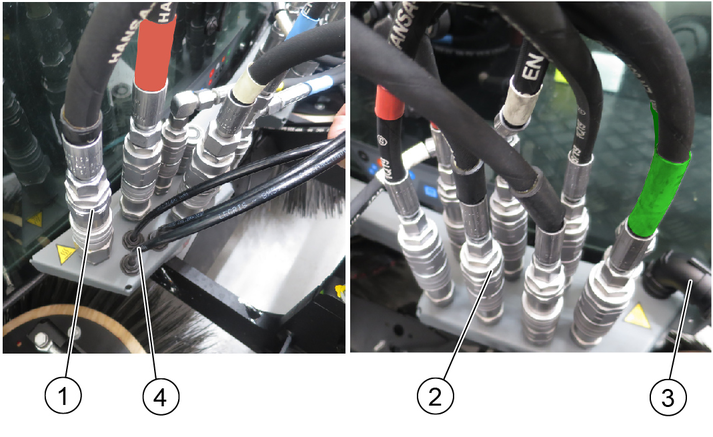
Connect the hydraulic hoses, noting the connection colours of the hydraulic hoses.
Connect (plug in) water hoses.
Insert the plug of the brush system electrical connection into the power supply.
Remove both locking plates on the front brush arm and front brush.
Individually raise and extend the side brushes.
Move the changing carriage out of the way.
Lower the waste container completely.
The indicators in the switches light when the switches are switched on.
Joystick forwards: 3rd brush lowers and switches on
Increase the contact pressure in the case of heavy soiling
Joystick backwards: 3rd brush raises and switches off
Joystick to the left/right: 3rd brush moves to the left/right
Joystick forwards: Lower the brush arms simultaneously and switch on the sweeping brush
Joystick backwards: Raise the brush arms simultaneously and switch off the sweeping brush
Joystick to the left/right: Pivot the brush arms simultaneously
Press the button for longer than 2 seconds, the suction mouth is in the floating position
Press for longer than 2 seconds, dosage of recycling water adjustable
(A) | 3rd brush rotary speed selection (front brush) |
(B) | Sweeping brush rotary speed selection |
(C) | Engine speed Press to adjust the values NoteThe suction performance depends on the set engine speed.
|
(D) | Pressure relief of sweeping brush |
(E) | Pressure relief of 3rd brush (front brush) |
(F) | Save button Press to save adjusted values or programs |
(G) | Rotary knob Press to change the adjusted values |
The front brush must be secured in the desired position when using the device as a weed brush.
Three positions are possible.
Secure the desired working position with bolts and spring pins. See chapter Transport lock.
Press the Change of rotation direction button when working in the Left position.
The front brush must be secured when driving on public roads (transport journeys).
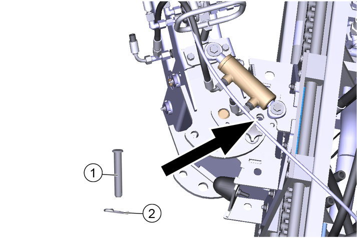
Move the front brush carriage all the way to the left.
Secure the front brush in the corresponding position using a pin and spring pin.
Further information can be found in the operating instructions for the vehicle.
Maintenance and care of the sweeping unit
Check the front brush and sweeping brush for tangled cords and straps and remove as necessary.
Keep the hydraulic connections clean and check for leaks once a week.
Check the front brush and sweeping brush for wear and tear and replace if necessary.
Maintenance and care of the bearings/linear unit
Malfunction or risk of damage
The bearing units are self-lubricating dry bearings and must never be lubricated with any lubricant.
Brake cleaners, lubricants or other cleaners can corrode and destroy the bearing foil. Check the bearing foil for wear and damage and replace if necessary.
The existing lubrication points (grease nipples) are labelled.
Lubricate daily with multi-purpose grease.
Clean the entire linear unit with water or brine. Cleaning with a high pressure cleaner is not a problem.
Maintenance and care of the chain
Notes on lubricating the chain
When lubricating the chain, make sure that no lubricant gets onto the rails of the linear unit. Should this happen due to carelessness, they must be cleaned and free of grease before initial startup.
Never use stains or acids to clean the chain.
Inspect the chain at least once a month. During the inspection, clean the chain, tension the chain drive and lubricate it.
The chains can be cleaned with rags or brushes. Stubborn dirt can be loosened with petroleum or benzine. Apply new, suitable corrosion protection immediately after using grease-dissolving media.
The chain drive may only be tensioned by Kärcher Service.
Regular lubrication extends the service life. Lubricate the chain with relubricant VP8 FoodPlus Spay from IWIS.
Note that the lubricant must get into the chain joint. This means that it has to get between the protective roller and the bushing, and also between the inner and outer plates to the pins and bushing
If you notice a lack of lubrication in the form of increased noise, stiff joints or fretting corrosion in the joints, we recommend the following procedure.
Clean the chain with a very low viscosity oil. This flushes fretting corrosion, old lubricant and other dirt from the joint. When the chain has been cleaned, lubricate it with a suitable lubricant as described above.
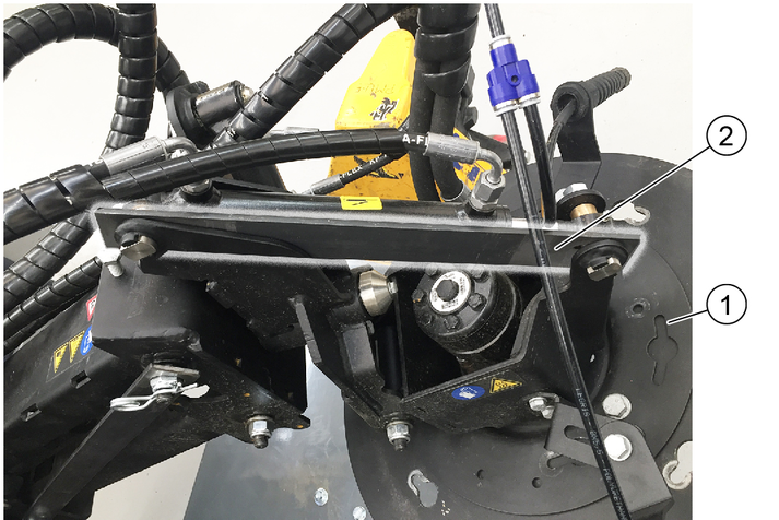
Adjust the sweeping area as shown in the illustration.
Right: 9 am- 2 pm
Right-hand side: 10 am- 3 pm
Adjusting the side inclination
Unscrew the screws.
Adjust the side inclination via the rotation point of screw 1.
Tighten the screws.
Adjusting the head inclination forwards
Unscrew the counternut.
Adjusting the head inclination via the hexagon.
Tighten the counternut.
Adjusting the brush contact pressure
The brush system has a hydraulic brush contact pressure adjustment system.
Risk of injury and damage
Note the weight of the device.
Risk of damage
Store the attachment kit in a protected, level and dry place. Ensure that the sweeping brushes are not loaded.
Store the sweeping system that has been removed from the vehicle on the changing carriage.
Ensure that the sweeping brushes are not loaded during attachment to the vehicle.
The following additional symbols and warning indicators may be shown on the display when sweeping.
 | Suction mouth is down (lowered) |
 | Suction mouth camera activated |
 | Recycling water level low |
 | Waste container/platform cannot be operated |
 | Waste container is raised |
 | Intersection function active |
 | Warning, recycling water level too low - do not switch on the water circulation function (recycling water) |
 | Warning, the waste container is raised |
 | Warning, the waste container lid is open |
The vehicle has an intersection function. This allows the broom system and the suction mouth to be raised and the rotation of the brushes and the water supply switched off at the push of a button. Everything can then be reactivated after this.
Press the travel direction selector switch to the end position.
The intersection function is activated and an indicator lights up in the display.
Press the travel direction selection switch again.
The intersection function is deactivated and the indicator in the display goes out.
The brushes turn again, the suction mouth is lowered and the water supply starts again.
The cleaning work continues with the previously set values.
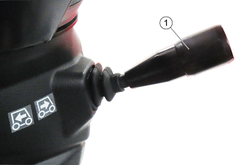
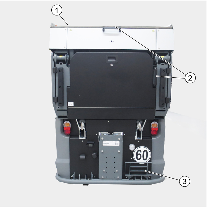
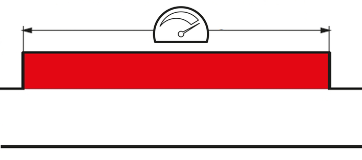
A sound proofing attachment kit is installed at the factory can be recognized by an additional label 99 dB (A) on the rear of the waste container.
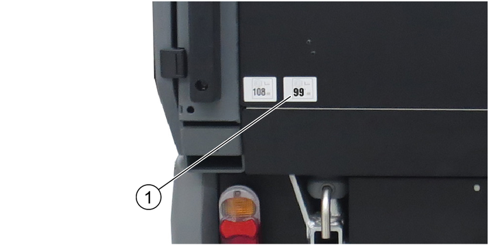
The sound proofing of 99 dB (A) is achieved when the engine speed is set to 1400 rpm.
The open flap of the manual suction hose provides overflow protection when filling
Swing the left side panel outwards.
Remove the cover from the filler neck and attach a suitable water supply hose.
Unscrew the fresh water tank cap.
- Open the manual suction hose flap
Select the position of the switchover valve accordingly. Fill the fresh water tank or recycling water tank.
Maximum fresh water tank filling quantity: 190 litres
Maximum recycling water tank filling quantity: 445 litres
Fit the cover again after filling.
Working with fresh water
The dosing buttons for the spray water are located next to the steering wheel.

Switch on the fresh water pump at the switch on the arm rest control panel.
Turn the corresponding dosing buttons to adjust the water quantity.
More water quantity: Turn anti-clockwise.
Less water quantity: Turn clockwise.
Working with recycling water
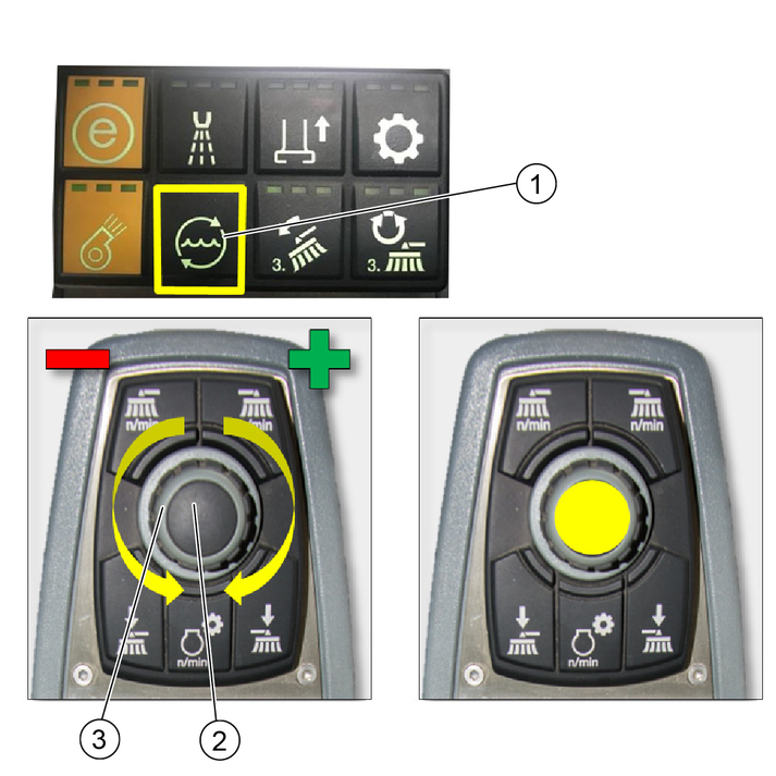
Switch on the recycling water pump at the switch on the control panel on the arm rest. Hold pressed for at least 2 seconds.
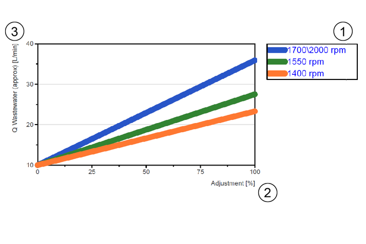
Use the rotary knob on the control panel to set the required water quantity according to the amount of sweeping waste (see following diagram).
Note: The water quantity must always be adapted to the level of soiling. Excessive amounts of water lead to a leak in the device exhaust air and can impair the machine environment
Confirm by pressing the save button.
The output in% is shown as a bar on the display.
In the recycling operation, the filled water is circulated in the waste water tank/waste container.
This is conveyed to the suction mouth via a centrifugal pump.
This recycling water is immediately sucked into the suction mouth, cleaned by the side filters and returned to the waste water tank/waste container via the valve.
The system has a deficiency sensor for indicating a low level of circulating water. When the limit value is reached, the pump is switched off (LED in the center console goes out).
In this case, fresh water can be reintroduced into the circuit via the water nozzles in the suction mouth.
The operation or the assignment of the control console can be found in the chapters of the 2-brush sweeping system or 3-brush sweeping system.
Briefly press the pedal: Full brush pressure and increased brush speed for heavy soiling.
Hold the pedal pressed: Suction mouth remains lowered when reversing, vacuumed substances are also taken up when reversing.
Check the filling level of the waste container from time to time.
With normal waste, empty the waste container when the container is almost full, at the latest when the suction performance decreases and dirt remains.
In the case of heavy waste, a display can light up that indicates a full waste container (weight measurement) even though the waste container is not full.
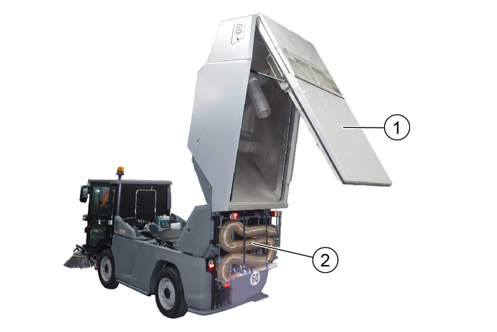
Lift the waste container until the waste container lid has opened.
Use the climbing aid and handles to check the filling level.
Flush the suction system with water daily after finishing work.
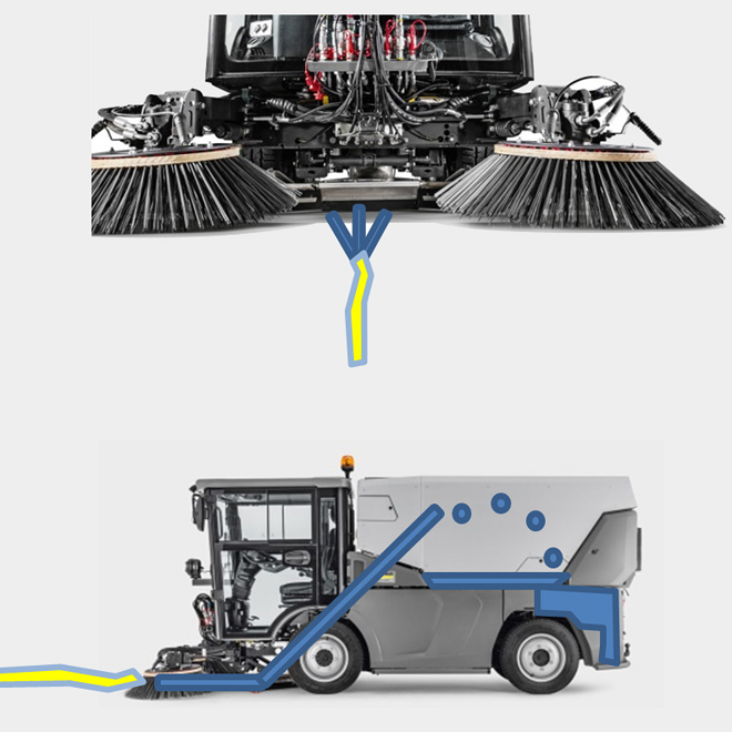
Figure: Cleaning the suction mouth and suction system
Park the vehicle.
Switch on the working hydraulics.
Switch on ECO mode.
Select an engine speed of 1550 rpm.
Raise the side brushes.
Place the water jet in the area of the suction mouth for approx. 3 minutes. The suction mouth and suction system are rinsed and cleaned.
The waste water collects in the waste container. Drain the waste water if necessary. See chapter “Draining waste water / recycling water”.
Drain the waste water or recycling water only in a suitable area.
Park the vehicle in a suitable area for emptying.
Switch on the vehicle.
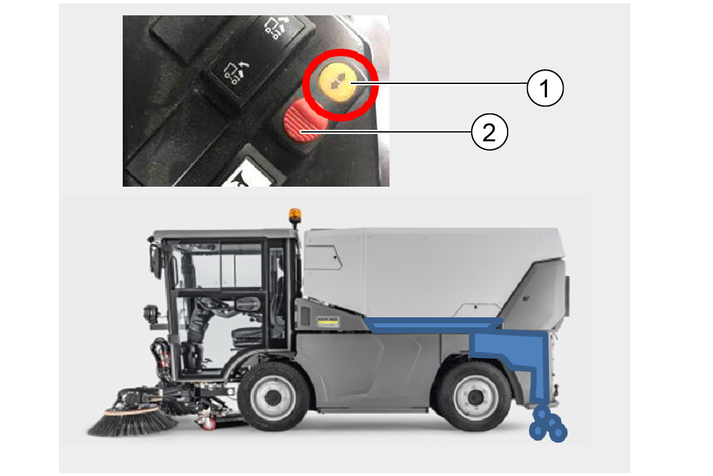
Use the "Drain recycling water" switch. For this, press the lock and operate the switch. The recycling water valve opens.
The switch is located on the side panel.
Drain off waste water or recycling water.
Leave the recycling water valve open during longer standstill periods.
Engage the lock to avoid unintentional activation of the switch (when entering/exiting).
Clean the recycling system with water every day after finishing work.
Find a suitable parking position and park the vehicle.
Switch off the sweeping system.
Open the recycling water tank and drain the water in the tank.
Raise the waste container for better access.
Attach the water hose to the water connection and connect to the house water connection.
Turn on the water.
System is flushed in both directions in parallel.
Recommended flushing time is 5-10 minutes.
The system cleaning is finished when clear water emerges from the suction mouth and the recycling water tank at the drain outlet.
Note: To avoid malfunctions, the water connection (GEKA) must not be closed.
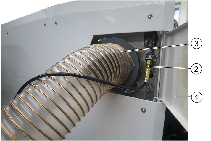
The fan cleaning attachment kit (2.852-587.0) can be used for cleaning, if installed.
Remove the blind cover of the C-coupling at the fan cleaning connection.
Connect a water hose and connect it to the domestic water supply. An adapter from GEKA to C-coupling is required for this (not included in the scope of delivery).
Preselect a motor speed of 1400 rpm.
Switch on the PTO and blower (ideally with the waste container closed).
Open the water inlet.
Operate the blower and until the desired result (approx. 3-5 minutes) is achieved.
Reattach the blind cover.
Clean the suction mouth and the suction system first before cleaning the waste container. See chapter “Cleaning the suction mouth and suction system”.
Park the vehicle.
Raise the waste container into the emptying position.
Rinse the inside of the sweep container and the side channels with water.
If necessary, rinse the exhaust grille with water by pulling out the retaining clips on the left and right and pivoting the blow-out grille down.
Rinse the outside of the blower flap with water, first open the blower flap with the rod (the rod engages).
The vehicle with the waste container can be cleaned with a high-pressure cleaner.
Clean critical areas such as bearings, tyres, etc. with reduced pressure and without a rotary nozzle.
Do not clean areas with electrical components with the high-pressure cleaner.
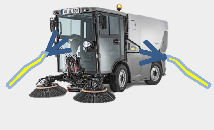
Figure: Cleaning the vehicle
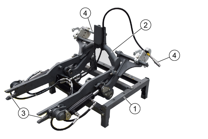
Front power lift 2.852-755.0
This chapter describes the attachment and removal of a front power lift on an MC 250.
Various different attachments can be attached to the front power lift using a 3-point mounting.
The attachment kit may only be used as intended.
We recommend using a changing carriage 2.852-067.0 when attaching to the vehicle.
When attaching the front power lift for the first time (approx. 110 kg), use a crane or similar to position it on the changing carriage.
Stop the vehicle on level, solid ground and secure it against rolling away.
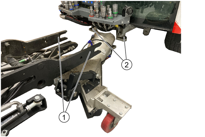
Open the lock, see chapter “Opening/closing the lock”.
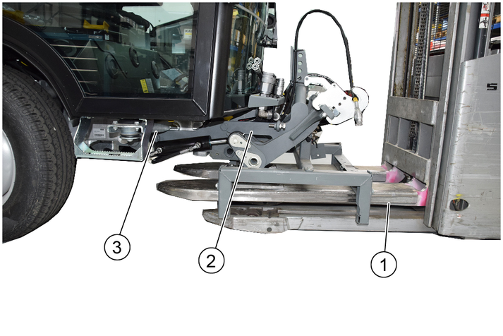
Position the changing carriage with front power lift with the lift truck in the middle in front of the vehicle, then insert it into the vehicle mounting frame as far as it will go.
The front power lift mountings must engage in the left and right attachment points of the vehicle.
Tighten the lock on both sides with screws and secure with a lock nut.
An open ring spanner is required to counter the nut
See also chapter "Opening/closing the lock"
Lower and retract the lift truck.
Secure the power lift against uncontrolled lowering while it is being coupled hydraulically. Caution: There is a risk of injury from the uncontrolled lowering of the power lift.
Depressurise the front hydraulic system (pressure relief).
See chapter “Depressurising the hydraulic system” in the operating instructions for the vehicle.
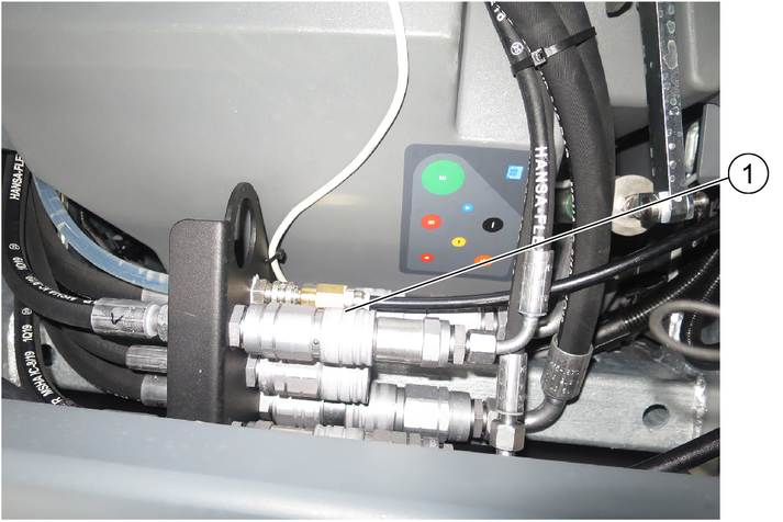
Connect the hydraulic hoses to the couplings (note the colours).
Select "Implements" in the “Attachments/Implements” menu in the vehicle display.
Refer to the chapter "Display" in the operating instructions of the vehicle.
Deactivate pressure relief.
The front power lift is operated using the left joystick on the vehicle.
Left joystick forwards - front power lift lowers.
Left joystick back - front power lift raises.
Raise the front power lift.

Use a lift truck to move the changing carriage under the front power lift.
Raise the lift truck.
Make sure that the frame of the front power lift is securely seated in the mounting of the removable frame.
Depressurise the front hydraulic system (pressure relief).
Release the hydraulic hoses.
Fasten the hydraulic hoses to the front power lift with cable ties.
Open the lock on both sides of the vehicle, see chapter “Opening/closing the lock”.
Use a lift truck to move the front power lift out of the vehicle mounting frame.
Set down the front power lift in a safe place.
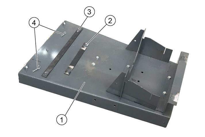
Possible attachments on the attachment frame: Spreader, water drum or the grass / leaf vacuum container on a mower / vacuum combination.

All 4 locking buttons must first be attached, adjusted and secured with the counternuts.
The locking buttons 6.321-295.0 are part of the "Attachment frame" attachment kit
Screw the locking button into the thread of the welded nut on the frame and adjust it.
If the setting is correct, the bolt of the pulled locking button releases the slot for the supports.
Secure with counternut.
Attach the attachment frame to the vehicle.
Remove the retaining clip and pull the locking rods out of the attachment frame.
Lower the attachment frame onto the vehicle using a crane (if available) until the attachment frame sits securely in place in the 4 ball sockets. Use the assistance of a second person if necessary.
Push in the locking rods.
Secure with the retaining clip.
The corresponding attachment can be positioned and fastened on the attachment frame once this is securely attached to the vehicle and secured, see the operating instructions for the attachment.
The attachment frame with the attachment can only be removed using the "Supports" attachment kit. A detailed description is provided in the chapter "Removing the waste container".
The high-pressure cleaner attachment kit is included in the scope of delivery and already installed in the vehicle when ordered ex-factory.
This chapter describes operation and care.
With a built-in additional water tank the attachment differs slightly:
The position of the high pressure cleaner in the unit. The hose reel for the high-pressure hose is omitted with this equipment variant.
To remove the additional water tank, follow the instructions in the chapter "Additional water tank attachment (ex-factory)" in these instructions.
Before removing the additional water tank, loosen the hose coupling to the high-pressure hose and remove the hose from the holder
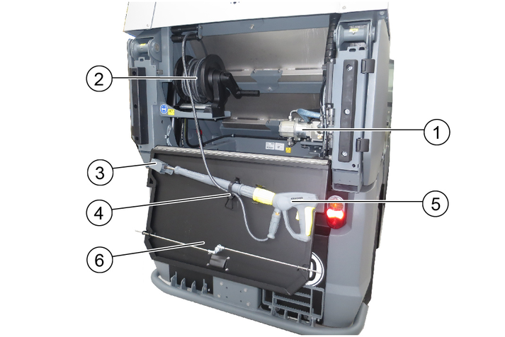
Removing the high-pressure hose from the holder
Open the high-pressure hose holder
Turn the hose hook to open
Open the spray unit holder.
Remove the spray unit and the high-pressure hose from the holder.
After work, first roll up the high-pressure hose onto the holder and then hang the spray unit in the holder. Rolling up is easier if the upper hose hooks are turned upwards beforehand.
Do not overtighten the high-pressure hose holder.
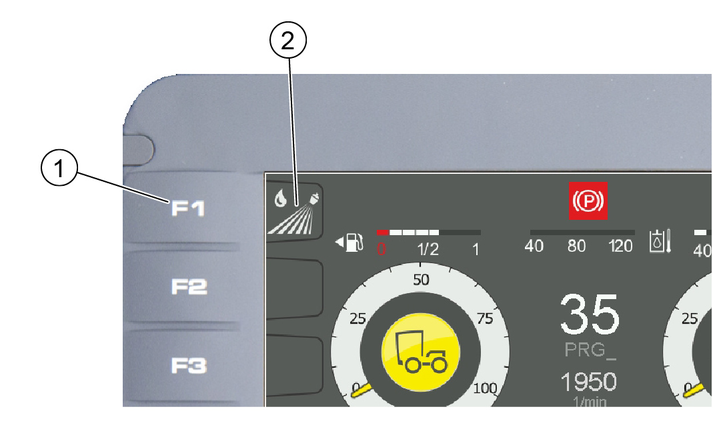
The following symbols and warning indicators are shown on the display when operating with the high-pressure cleaner.
 | High-pressure cleaner is activated |
 | High-pressure cleaner inactive |
Use the high-pressure cleaner only for the following activities:
Cleaning with the high-pressure jet without detergent (e.g. façades, park seats, garden paths).
Only operate the high-pressure cleaner with the flat jet nozzle provided.
This high-pressure cleaner is intended and tested for the exclusive use with the sweeper vacuum MC 250.
When the water quantity is reduced via the pressure/quantity control on the trigger gun, the overflow valve opens and part of the water flows back to the suction side of the pump.
The safety valve opens when the permissible operating pressure is exceeded and the water flows back to the suction side of the pump.
Return flow of dirty water into the drinking water network
Health risk
Observe the regulations of your water supply company.
According to applicable regulations, the device must never be used with the drinking water network without a system separator. Use a system separator from KÄRCHER or a system separator as per EN 12729 Type BA. Water that has flowed through a system separator is classified as undrinkable. Always connect the system separator to the water supply and never directly to the water connection on the device.
Risk of injury from high-pressure jet
Do not direct the high-pressure jet at persons, animals, live electrical equipment or at the device itself.
Protect the device high-pressure cleaner frost.
Environmental pollution through oil
Clean engines only at locations having an appropriate oil separator.
Only nozzles of the sizes listed in the technical data may be used.
If you have not already done so:
Connect the high-pressure hose and spray lance.
Connect the water supply hose and open the stop cock of the water inlet.
Check the water level and, if necessary, fill the fresh water tank of the MC 250.
Open the stop cock of the water inlet.
Put travel direction lever in the NEUTRAL position - centre position and start the motor.
Remove the trigger gun and high-pressure hose from storage.
Switch on the PTO work hydraulics.
Deactivate the seat contact switch (F4 button on the display).
Switch on the high-pressure cleaner in the display with the F1 button.
The engine speed increases automatically.
High-pressure active (orange) appears in the display.
Unlock the trigger gun.
Pull the trigger on the trigger gun and commence cleaning.
The high-pressure cleaner must be vented when first used or when the water reservoir is empty:
Operate the high-pressure cleaner without the nozzle until there is no more air in the system.
Close the trigger gun.
Switch off the high-pressure cleaner in the display with the F1 button.
Switch off the work hydraulics.
Actuate the trigger gun until the device is depressurised.
Actuate the safety lever of the trigger gun to prevent the gun trigger from being unintentionally triggered.
Fasten and secure the trigger gun with spray lance and high-pressure hose in storage.
Check all hydraulic hoses and connections for leaks.
Check the high-pressure hose for damage (danger of bursting).
Immediately replace a damaged high-pressure hose.
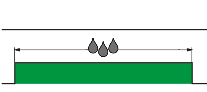
Check the device (pump) for leaks.
3 drops of water per minute are permissible and can leak out of the bottom of the appliance. Contact Customer Service in the case of more serious leaks.
Read the oil level when the device is on a flat surface.
The oil level must be in the middle of the sight glass.
Contact Customer Service immediately if the oil is milky (water in oil).
Clean the water filter.
Depressurise the device.
Unscrew the filter casing.
Clean the filter with clean water or compressed air.
Changing oil.
See the chapter "High-pressure cleaner technical data" for the oil volume and type.
Have the oil changed by Customer Service.
Danger of frost
Incompletely emptied devices can be destroyed by frost.
Completely empty the device and accessories.
Protect the device from frost.
Store the device in a frost-protected place.
If frost-free storage is not possible:
Close off the water inlet.
Allow the device for run for a maximum of 1 minute until the pump and lines are empty.
Blow the high-pressure pump, supply hose, water filter and high-pressure hose out with compressed air.
Risk of injury due to inadvertently starting up device and also due to electric shock.
Switch off the device and remove the ignition key before performing any work.
Have electrical components checked and repaired by the authorised Customer Service.
In case of any malfunctions not mentioned in this chapter, contact the authorised Customer Service when in doubt or when you have been explicitly advised to do so.
Remedy:
Switch on the work hydraulics (PTO).
Remedy:
Activate the high-pressure cleaner attachment kit (display F1).
Remedy:
Fill the fresh water tank.
Remedy:
Clean the water filter, check water supply.
Remedy:
Check/replace the high-pressure nozzle.
Pump leaking
Up to 3 drops of water per minute are permissible.
Remedy:
In case of more serious leaks, have the device checked by Customer Service.
Pump knocking
Remedy:
Check the water supply line for leaks.
Vent the device, see section "Venting the device".
Contact Customer Service if necessary.
Hydraulic connection | ||
|---|---|---|
Supply from the hydraulic system of the MC 250 | ||
Connection output | kW | 4.5 |
Water connection | ||
Water supply from the fresh water tank of the MC 250 | ||
Input temperature (max.) | °C | 60 |
Performance data | ||
Working pressure | MPa | 7-15 |
Nozzle size | 036 | |
Max. operating pressure | MPa | 19 |
Flow rate | l/min | 10 |
Recoil force of the trigger gun. (max.) | N | 30 |
Determined values according to EN 60335-2-79 | ||
Sound level KpA | dB(A) | 75 |
Uncertainty KpA | dB(A) | 3 |
Sound power level LWA + uncertainty KWA | dB(A) | 97 |
Hand-arm vibration value | m/s2 | 1.6 |
Uncertainty K | m/s2 | 0.7 |
Operating materials | ||
Oil volume | l | 0.4 |
Oil type | SAE 15W-40 | |
We hereby declare die technical documents according to EC Directive 2006/42/EC (+2009/127/EC) Annex VII Part B have been created for the incomplete machine described below and that this conforms to the following points of the directive:
Annex I Points 1.1, 1.2, 1.3, 1.4, 1.5, 1.6 and 1.7. I Point 1.1,
This declaration is invalidated by any changes made to the incomplete machine that are not approved by us.
Product: | Attachment kit |
High-pressure cleaner | |
Type: | 2,852-757.7 |
Harmonised standards used, based on: | |
EN 60335–2–79 | |
Authorities can request the relevant documentation for the incomplete machine from the documentation supervisor. Documents are provided via email.
Before commissioning or installation of the incomplete machine, it must be ensured that the complete machine into which the incomplete machine is installed conforms to the EC Machinery Directive 2006/42/EC (+2009/127/EC).
Please refer to the EC Declaration of Conformity for the machine for more information on this.
The signatories act on behalf of and with the authority of the company management.
Documentation supervisor:
S. Reiser
Alfred Kärcher SE & Co. KG
Alfred-Kärcher-Str. 28 - 40
71364 Winnenden (Germany)
Ph.: +49 7195 14-0
Fax: +49 7195 14-2212
Winnenden, 2019/11/01
The central lubrication attachment is part of the scope of delivery when ordered ex-factory.
The central lubrication system is ready for operation on delivery and all settings (lubrication duration and interval) are adapted and set to the delivered vehicle. Intervention by the operator is not necessary.
The lubrication work according to the maintenance schedule (see chapter "Care and maintenance of the vehicle and attachments") is not required due to the central lubrication system.
The central lubrication system has a lubricant tank that must be filled by the operator.
Danger of environmental damage due to leaking lubricants
Lubricants escaping during filling are harmful to the environment!
Do not overfill the container (observe marking), watch out for escaping lubricants when filling and wipe it up immediately.
Please be sure to observe the original instructions enclosed with the unit and the safety instructions contained therein!
Risk of damage
The unit can be damaged by incorrect filling!
Only refill the lubricant tank at the filling nipple.
Risk of damage
Damage to the vehicle and attachments due to incorrect lubricant!
Use only approved lubricant. See chapter "Technical data/Lubricants" in the vehicle operating instructions.
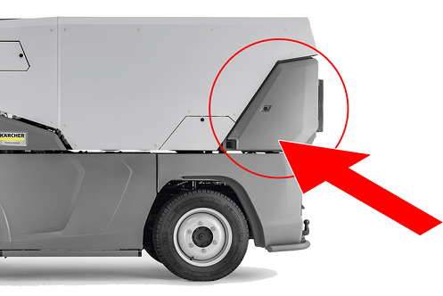
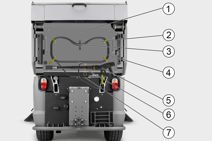
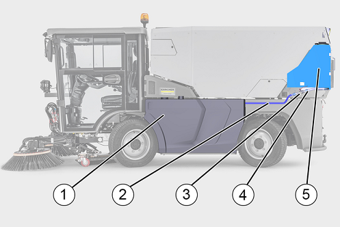
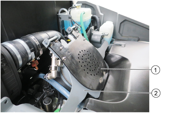
The pump unit and the lubricant tank of the central lubrication system are installed in the rear of the vehicle and are accessible via the rear cover of the left or right side of the vehicle (depending on whether an additional water tank attachment kit is installed).
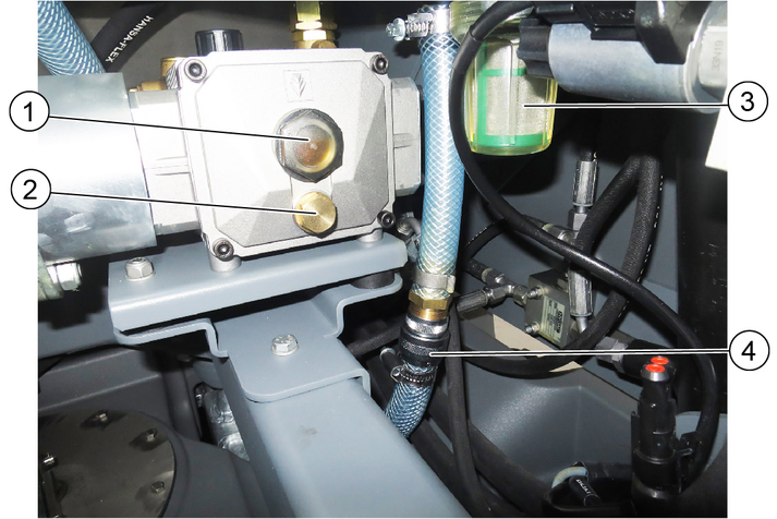
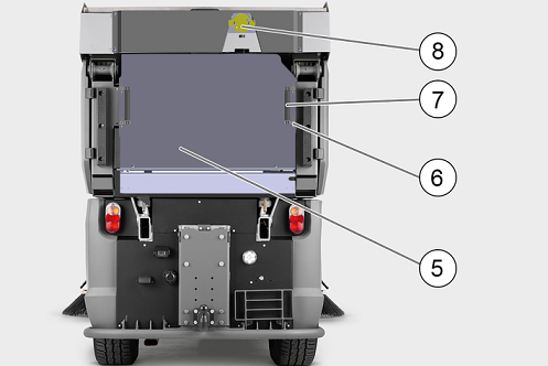
Overview of the unit
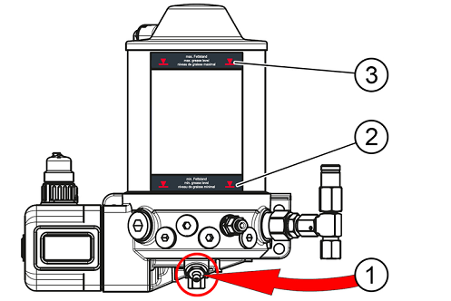
Filling nipple
Filling level marking "Min"
Filling level marking "Max"
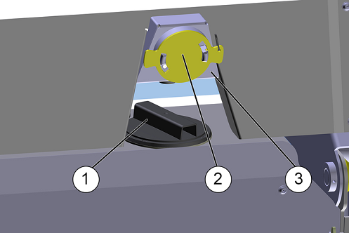
Control unit
The control unit is located under a cover with a sight glass. Settings may only be made by the authorised service.
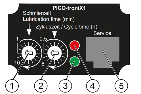
Lubrication time
Cycle time
Indicator light green
Indicator light red
Diagnostic and service interface.
Vehicle is parked, ignition switched on.
The central lubrication system operates automatically according to the set parameters. The operating status can be read from the two indicator lights.
The unit is maintenance-free, except for the regular filling of the lubricant tank.
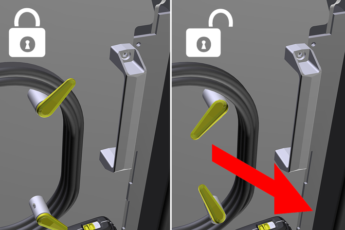
Risk of injury
Lubricant escaping under pressure
Only disconnect the connections of the central lubrication system when it is not in operation (lubrication cycle)!
Activities
Fill lubricant tank
Check the filling level of the lubricant tank.
Connect grease gun or filling pump to the filling nipple.
Fill the lubricant tank.
Observe the "Max" marking on the lubricant tank. Do not overfill the tank.
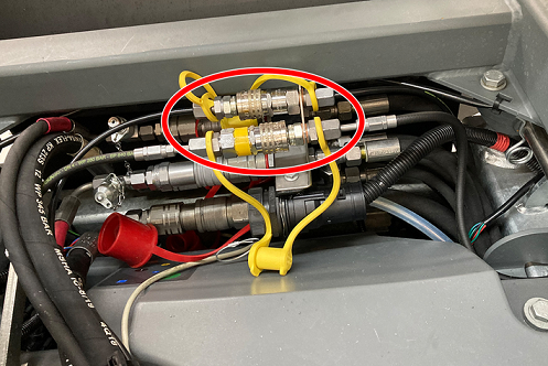
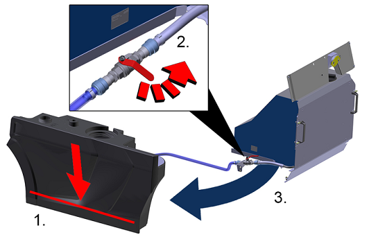
Removing attachment
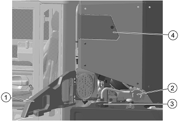
If an attachment (for example the brush system) is removed, the return line of the central lubrication system must be plugged into the connection of the lubricant line so that the lubricant circuit remains closed (bypass).
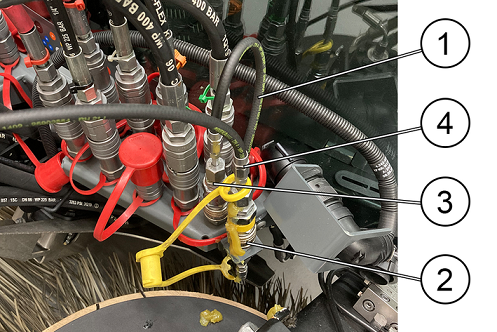
Operating status WITH attachment
Operating status WITHOUT attachment
Return line of the central lubrication system
Central lubrication system lubricant line
Storage (plug coupling) of the return line
Lubrication line attachment
The attachment can now be removed.
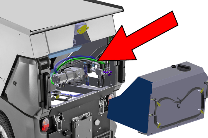
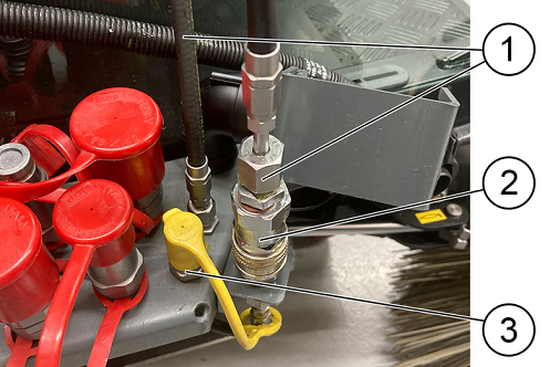
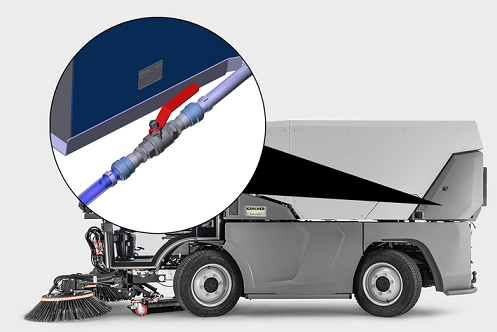
Removing the waste container
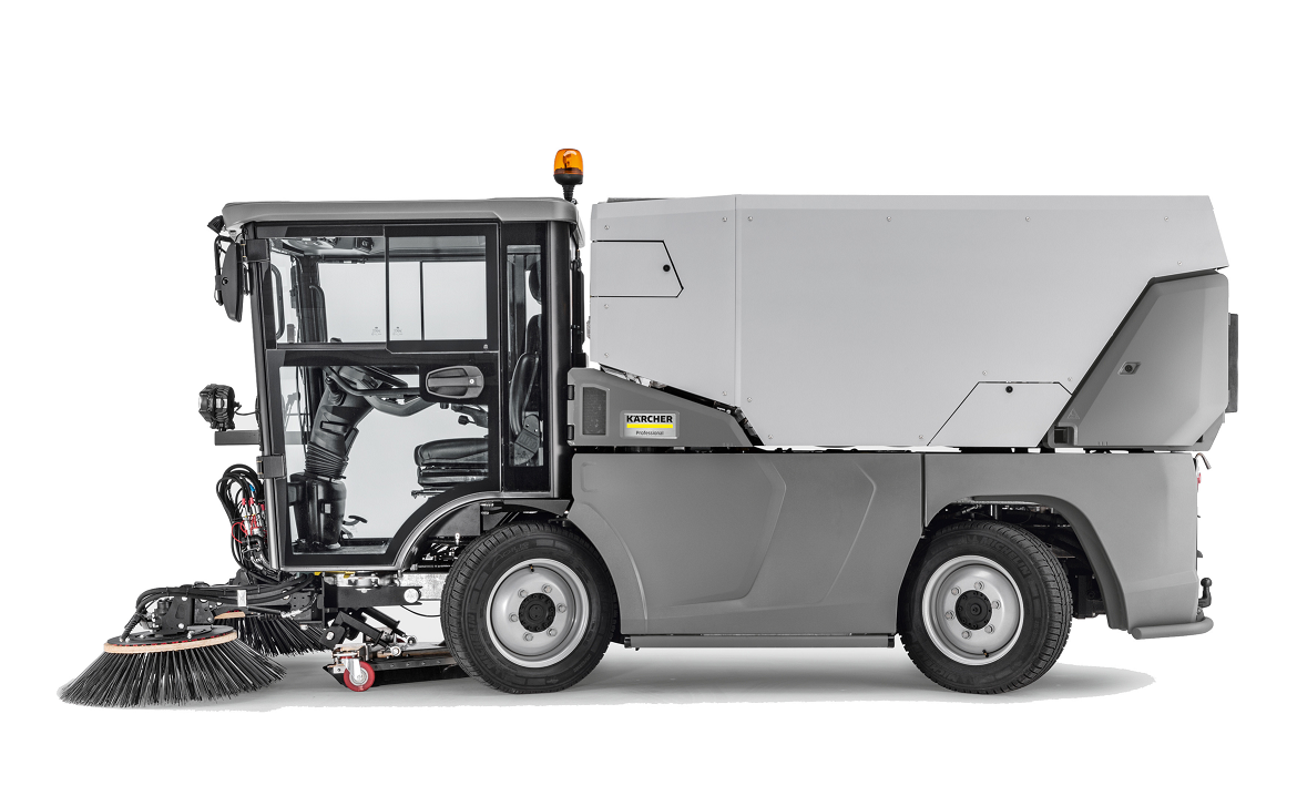
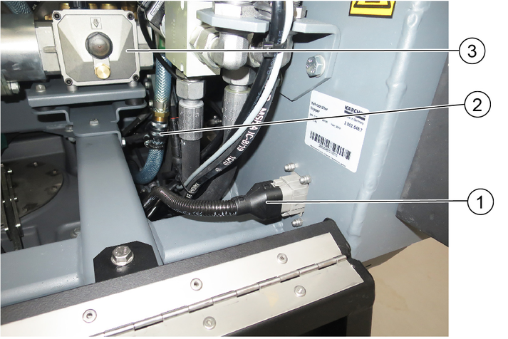
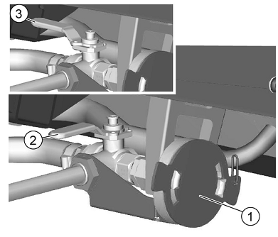
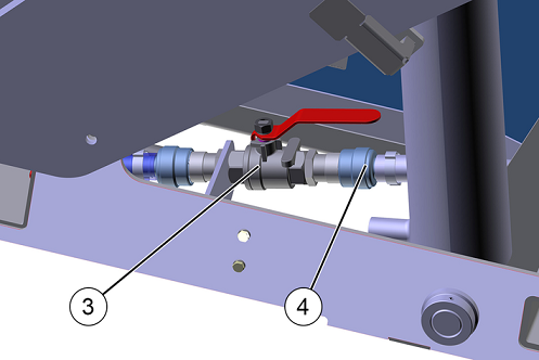
Before removing the waste container, the connections of the central lubrication system must be disconnected.
The lines to the lubrication points on the vehicle's water tank are firmly connected and must be disconnected at the point shown using a suitable tool.
Before disconnecting, place a cloth underneath and wipe up any grease that may escape.
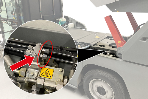
Disconnect the lubricant lines and the electrical connection.
The waste container can now be removed.
Visual inspection of the lubrication points
Regularly check all connections and lubrication points for leaks.
There are two indicator lights (red and green) on the control unit which indicate the current operating status of the central lubrication system via blink codes.
Normal operation
Display | Meaning |
|---|---|
 | After switching on the ignition: The system is ready for operation. |
 | Lubrication is in progress. Display throughout the duration of lubrication, then ready display. |
Fault displays
Fault display | Malfunction | Removal |
|---|---|---|
 | Lubricant tank empty. | Fill up the container, the display disappears. |
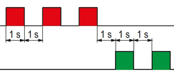 | Leakage in the system | Check connections, lines and lubrication points for leaks. If the error is not found, contact the service department. |
The control unit outputs other blink codes not mentioned here. In the event of such an error message, please notify Kärcher Service.
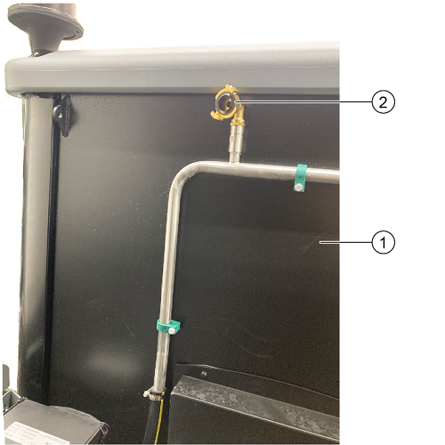
The additional water tank attachment is part of the scope of delivery when ordered ex-factory.
The additional water tank is located at the rear of the vehicle.
The additional water tank can be removed from the vehicle without tools for servicing.
Vehicle is parked and not in use, the parking brake is applied.
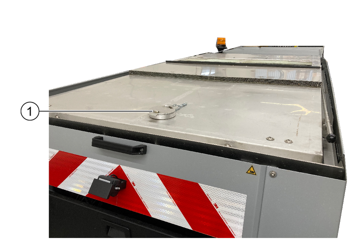
Filling the additional water tank
Remove the reservoir cover.
Remove the hose connection protective cover.
Connect up the water hose.
Fill tank.
Before filling, check that the ball tap (see below) is closed. Check the water level regularly during filling to avoid overflowing. The additional water tank has no filling level display or automatic water supply cut-off.
Refit the reservoir cover and protective cover.
Functional principle of the additional water tank
Working with the additional water tank
The ball tap may only be opened when the fresh water tank of the vehicle is empty.
Stop the vehicle if the fresh water tank is empty (notification via the vehicle interface).
Open the vehicle cover at the rear left.
Open the ball tap.
Fresh water tank is being filled.
When the ball tap is open, sweeping can be continued with the vehicle
Removing the additional water tank
The additional water tank can be removed from the appliance for servicing or cleaning.
The additional water tank must be completely empty for removal!

Open the rear vehicle cover.
Disconnect the connection hose at the quick coupling.
Open the quick-release catches on both sides of the tank.
Pull the tank out of the vehicle to the rear.
The manual suction hose is included in the scope of delivery when ordered ex-factory.
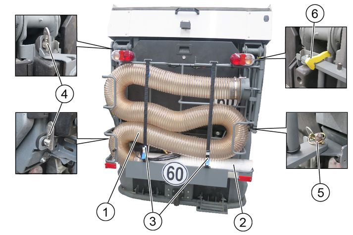
Removing the attachment from the vehicle
The attachment can be easily removed if not required.
To remove, pull out the lynch pin and open both locking wedges. Then remove the attachment with 2 people.
Pivoting the attachment to the side
The attachment must be pivoted completely outwards in order to empty the waste container.
To do this, open both locking wedges and pivot the attachment all the way out to the side wall, where it is held by a magnet. Push the locking hook upwards before pivoting back.
The vehicle is parked and the travel direction selector switch is in the NEUTRAL position (middle position).
Working with the manual suction hose
Lift the waste container until the rubber flaps can be folded down.
Fold the rubber flap down over the suction opening.
Lower the waste container again.
Open the clamp lock belt and remove the manual suction hose with the manual suction pipe from the storage compartment.
Open the flap on the desired side.
Insert the manual suction hose into the connection opening and turn it (bayonet).
Plug in the water hose if necessary.
Switch on the work hydraulics (PTO).
Switch on the blower via the switch (control console).
Deactivate the seat contact switch (F4 button on the display).
Work with the manual suction hose.
After finishing work:
Switch off the work hydraulics.
Activate the safety contact switch.
Place the suction hose with the suction pipe in the storage compartment and secure with the clamp lock belt.
Normal sweeping
Lift the waste container and fold up the rubber flaps.
Lower the waste container.