SB OB
59696900 (03/23)
59696900 (03/23)
 Read these original operating instructions and the enclosed safety instructions before using the device for the first time. Proceed accordingly.
Keep both books for future reference or for future owners.
Knowledge of the following terms is important for understanding the operating instructions. The technical terms in bold are used throughout these operating instructions.
Fresh water - raw water, tap water, city water
Base exchanger - WSO, water softening unit
Softened water - soft water
Reverse Osmosis (RO) - reverse osmosis
Concentrate - waste water enriched with salts and minerals from reverse osmosis
Permeate - osmosis water, demineralised water, deionised water
Processed water - water from a biological water treatment plant
 The packing materials can be recycled. Please dispose of packaging in accordance with the environmental regulations.
 Electrical and electronic devices contain valuable, recyclable materials and often components such as batteries, rechargeable batteries or oil, which - if handled or disposed of incorrectly - can pose a potential danger to human health and the environment. However, these components are required for the correct operation of the device. Devices marked by this symbol are not allowed to be disposed of together with the household rubbish.
Current information on content materials can be found at: www.kaercher.de/REACH
Please do not allow engine oil, heating oil, diesel and petrol to enter the environment. Please protect the ground and dispose of old oil in an environmentally friendly manner.
Dangers can be presented to the operator and other persons if the device is incorrectly operated or misused:
High water pressure
High electrical voltage
Detergent
To avoid danger to persons, animals and property, read the following documents before operating the system:
These operating instructions, including all safety instructions
The respectively applicable national regulations
The safety instructions provided with the detergent used
Ensure the following:
That you have understood all notes and instructions
That all users of the system are notified of the instructions and have understood them
All persons working on the erection, installation and operation of the system must:
Be appropriately qualified
Know and adhere to these operating instructions
Know and adhere to the applicable regulations
In self-service operation, ensure that clearly visible notices are present informing all users with regard to:
Potential dangers
Safety devices
Operating the system
Risk of burns from hot system components
Do not touch system components such as pumps and motors until they have cooled down.
Danger of injury
Do not use the system if persons without the proper protective clothing are in the vicinity.
Check the device and the accessories, such as the high-pressure hose, high-pressure gun and safety devices, to make sure they are in proper safe and reliable condition before each operation. Do not use the device if it is damaged. Replace damaged components immediately.
Only use high-pressure hoses, control panels and couplings specified by the manufacturer.
Observe the respectively applicable national regulations for liquid jet cleaners.
Observe the respectively applicable national regulations for electrical installation.
Observe the respectively applicable national regulations for accident prevention. Have the system checked annually and store the written test results in a safe place.
Allow only KÄRCHER Customer Service technicians or KÄRCHER-authorised technicians to perform maintenance work and repairs.
Indication of an imminent threat of danger that will lead to severe injuries or even death.
Indication of a potentially dangerous situation that may lead to severe injuries or even death.
Indication of a potentially dangerous situation that may lead to minor injuries.
Indication of a potentially dangerous situation that may lead to damage to property.
 | WARNINGDanger from high electrical voltage. Have work on system parts with this symbol carried out by a qualified electrician only. |
 | DANGERRisk of burns due to high temperature. Do not touch surfaces marked in this way. |
 | ATTENTIONRisk of damage The storage surface for cleaning agents is designed for a maximum load of 50 kg. Do not step on this surface to prevent damage. |
The maximum sound level of the system is 80dB(A). Hearing protection is therefore not usually required.
When cleaning noise-intensifying parts, the sound level may increase. For this reason, wear suitable hearing protection in such cases.
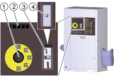
Turn the programme selection switch to "STOP".
Coins are inserted at the control panel and the washing programme is selected.
Cleaning is carried out with the high-pressure gun, washing brush and power foam lance.
Risk of injury, risk of burns
Only operate the system with the casing closed.
The inside of the system must only be accessible to trained personnel for maintenance work. When using the system, the door must be locked.
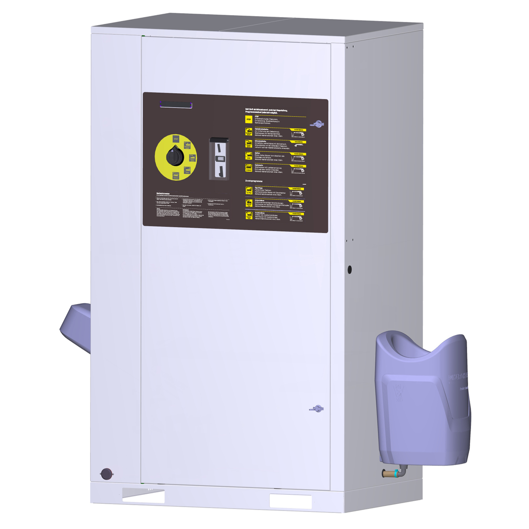
This self-service washing system is used for cleaning vehicles and trailers with water and detergent additives.
Cleaning humans and animals is improper use and
is prohibited.
The high-pressure water jet presents a substantial risk of injury.
Loose objects.
Loose objects can be propelled away at high speed by the high-pressure water jet and injure persons or damage other objects.
A category 5 system isolation must be installed between the system and the drinking water network to isolate the system from the drinking water network. Locally applicable regulations must also be observed.
Dirty water leads to premature wear or deposits in the device.
Clean the device using only clean water, or recycling water that does not exceed the following limits:
pH value: 6.5...9.5
Electrical conductivity: Conductivity of fresh water + 1200 µS/cm, maximum conductivity 2000 µS/cm
Settleable particles (sample volume 1 l, settling time 30 minutes): < 0.5 mg/l
Filterable particles: < 50 mg/l, no abrasive substances
Hydrocarbons: < 20 mg/l
Chloride: < 300 mg/l
Sulphate: < 240 mg/l
Calcium: < 200 mg/l
Total hardness: < 28 °dH, < 50° TH, < 500 ppm (mg CaCO3/l)
Iron: < 0.5 mg/l
Manganese: < 0.05 mg/l
Copper: < 2 mg/l
Active chloride: < 0.3 mg/l
Free of unpleasant odours
Systems without frost protection must be shut down when frost is expected.
When the prerequisites listed in the "Frost protection" section are satisfied, systems with frost protection can be operated at temperatures down to -20°C and must be shut down at lower temperatures.
For safety reasons we recommend operating the device only via a fault current protection switch (maximum 30 mA).
Switch on the on-site power supply.
Open the on-site water stop valve.
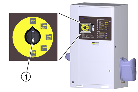
Unlock the locks.
Open the door.
Turn the trigger to 1/ON.
Close the door.
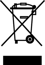
The active washing programme is selected using the washing programme switch.
The programme is interrupted.
Initial position. Cleaning tools in the tool mounts.
Note: The "STOP" function is active at all switch settings without a washing programme.
Loosening of stubborn dirt.
Water with special detergent additive.
Minimum high-pressure jet clearance of 80 cm.
Loosening of brake residue.
Water with special detergent additive.
Exposure time max. 2 minutes. Used before the car wash and only on coated or painted wheel rims.
For removing coarse dirt.
Water with detergent.
Minimum high-pressure jet clearance of 30 cm.
Thorough paint cleaning with active foam.
Use the washing brush only when a program is running and after the high-pressure wash.
Clear, cold water for rinsing off shampoo and foam.
Minimum high-pressure jet clearance of 50 cm.
Warm water with paint preservation.
Use only after rinsing.
Minimum high-pressure jet clearance of 80 cm.
Loosening of insect residue.
Water with insect cleaner.
Minimum high-pressure jet clearance of 30 cm.
Removal of stubborn dirt.
Water with special detergent additive.
Minimum high-pressure jet clearance of 30 cm.
Stain-free drying.
Demineralized water with a shine dryer.
Minimum high-pressure jet clearance of 80 cm.
Turn the program selection switch to the desired washing program.
Insert a coin or press the start button, depending on the version of the system.
While a washing program is in progress, water will escape from the nozzle of the cleaning tool even when the high-pressure gun is not actuated. Due to the frost protection function, the high-pressure gun does not close completely.
To clean with the high-pressure jet, press the locking lever, pull the cleaning brush back and lock it in place.
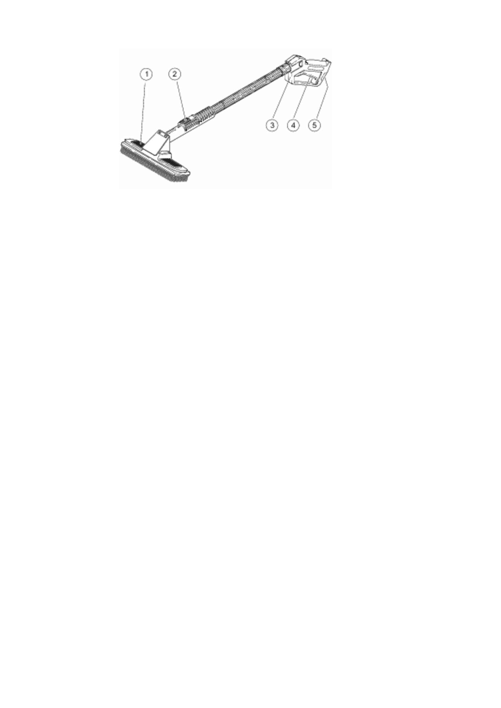
To clean with the cleaning brush, press the locking lever, push the cleaning brush forwards and lock it in place.
Release the safety catch.
Pull the trigger.
This version has a high-pressure gun and cleaning brush as two separate tools.
There are 3 separate tools here:
High-pressure gun
Cleaning brush
Power foam lance
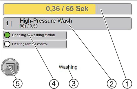
The washing time starts after inserting a coin or pressing the start button.
The remaining value display shows the remaining washing time.
Note:The washing time continues to run when the program selection switch is in the "STOP" position. If further coins are inserted during the washing time, these are registered and added to the existing washing time.
Unsuitable detergents can damage the system and the object to be cleaned.
Use only detergents approved by KÄRCHER. Observe the dosage recommendations and instructions provided with the detergent. Use detergents sparingly to help conserve the environment.
Incorrect handling of detergents can endanger your health.
Read and observe the safety and application instructions provided with the detergent before using the detergent. Wear the protective clothing/protective equipment specified in these documents.
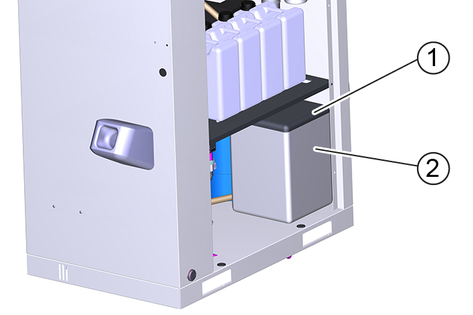
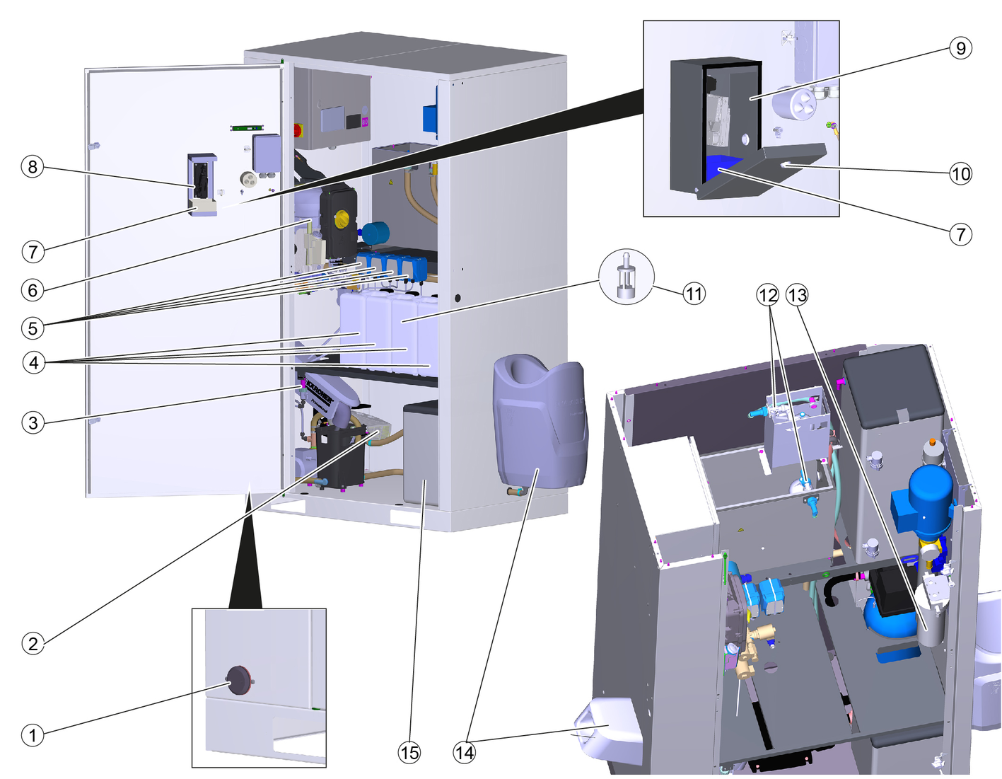
Open the device door.
Insert the detergent canister into the device.
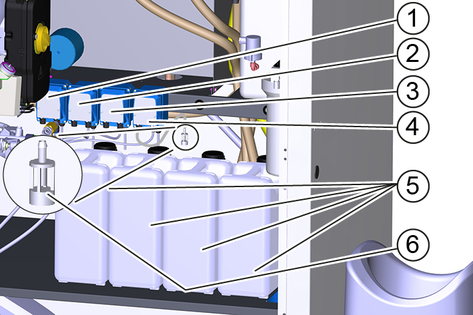
Dosing pumps and detergent suction filters are provided with colour markings.
Insert the detergent suction filter of the dosing pump into the detergent canister according to the assignment specified in the table below. Insert the hose far enough so that the filter lies on the bottom of the canister.
Dosing pump | Washing program | |
|---|---|---|
1 (yellow) | High-pressure wash | RM 806 |
1 (yellow) | Foam wash | RM 806 |
2 (red) | Hot wax | RM 820 |
3* (green) | Insects Loosening | RM 806 |
3* (green) | Dirt Loosening | RM 806 |
4* (green) | Power foam | RM 838 |
4* (white) | Power rim foam | RM 802 |
4* (red) | Top care | RM 821 |
* Option
Use the programme selection switch to select a programme that uses the relevant detergent.
Run the washing programme until the suction hose is bubble-free.
Malfunctions possible
Unsuitable salt can impair the function of the base exchanger.
Only use the softening salt in tablet form given in the "Accessories" chapter.
Remove the salt tank cover.
Fill the salt tank to the very top with softening salt.
Fit the salt tank cover.
An empty salt tank will cause a malfunction. Fill the salt tank at the latest when water is visible in the salt tank after removing the cover.
The salt consumption does not increase when the salt tank is completely full.
In a correctly working system, the salt consumption is constant in relation to the water consumption.
We recommend documenting the salt and water consumption in an operating log,
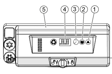
Press the hardness button on the control head of the base exchanger repeatedly until the desired interval is shown in the display.
0 | Deactivated |
0.3 | Regeneration every 8 hours |
0.5 | Regeneration every 12 hours |
1...30 | Regeneration every X days |
The factory setting is 0/Deactivated. The setting must be adjusted to the local conditions by the service technician when the device is installed.
The display shows the dosing amount in kg during the setting.
Press the salt button repeatedly until the desired brine dosage is shown on the display.
Target setting:
BA 42: 2.5 kg
BA 65: 4.5 kg
When setting, the current hour is selected. The minutes are reset to zero at the time of entry.
Press the time button repeatedly until the current hour is shown on the display.
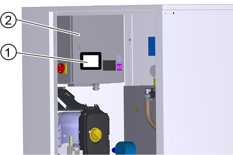
The touchscreen is mounted on the electrical box inside the system.
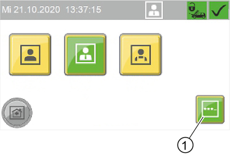
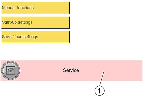
The following functions are displayed in the start menu.
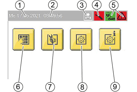
Start menu
Operating state symbols
 | System open |
 | System closed |
 | System OK |
 | Event present |
 | Malfunctions present |
User symbols
 | Operator |
 | Owner |
 | Service |
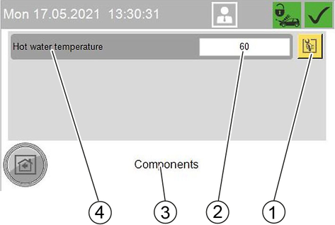
Press the Change Setting button next to the property you want to change.
 | Change Setting button |
A selection window opens to select the desired setting or a keyboard opens to enter the desired value.
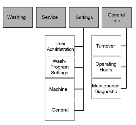
The current operating state of the system is displayed in the Washing menu.
The Service menu is only accessible for customer service.
The operating parameters of the system are set in the Settings menu.
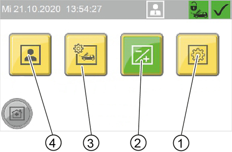
The user group is selected in the User Administration menu. Different user groups have different access permissions
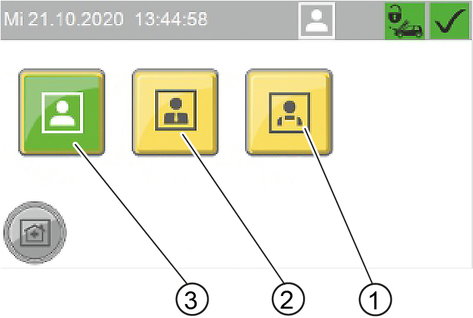
A code must be entered when selecting the user groups "Owner" and "Service".
Default code Owner: 1234
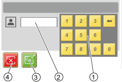
Changing code
For the user group Owner , the code can be changed after logging in.
Press the "..." button.
Enter the desired code in the "EnterNew Code" window.
Enter the same code again for confirmation in the "Confirm New Code" window.
The parameters of the individual washing programs are adjusted in the Wash-Program Settings menu.
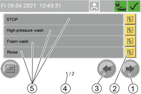
Changing the parameters of a washing program
Select the window with the desired washing program. Use the Next Window and Previous Window buttons for this.
Press the Change washing program button next to the desired wash program.
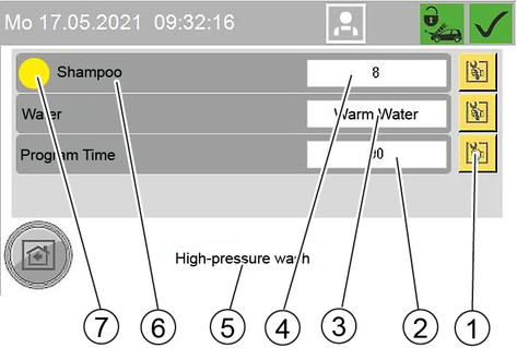
Press the button to change the desired parameter.
Press the desired parameter in the displayed selection.
Standard setting
Washing program | Dosing pump | water type | Program duration |
|---|---|---|---|
High-pressure wash | 1 (yellow) | Warm | 90 s |
Foam wash | 1 (yellow) | 135 s | |
Rinse | - | Cold | 105 s |
Hot wax | 2 (red) | Warm | 54 s |
Insects Loosening | 3 (green) | Warm | 75 s |
Dirt Loosening | 3 (green) | Warm | 75 s |
Power foam | 60 s | ||
Power rim foam | 60 s | ||
Top care | Cold | 75 s |
Washing program | Detergent dosing | |||
|---|---|---|---|---|
500 l/h | 900 l/h | |||
% | ml/min | % | ml/min | |
High-pressure wash | 8 | Approx. 6 | 16 | Approx. 12 |
Foam wash | 8 | Approx. 6 | 16 | Approx. 12 |
Rinse | - | - | - | - |
Hot wax | 10 | Approx. 7 | 20 | Approx. 14 |
Insects Loosening | 20 | Approx. 14 | 40 | about 28 |
Dirt Loosening | 20 | Approx. 14 | 40 | Approx. 28 |
Power foam | 30 | Approx. 21 | 30 | Approx. 21 |
Power rim foam | 30 | Approx. 21 | 30 | Approx. 21 |
Top care | 10 | about 7 | 20 | Approx. 14 |
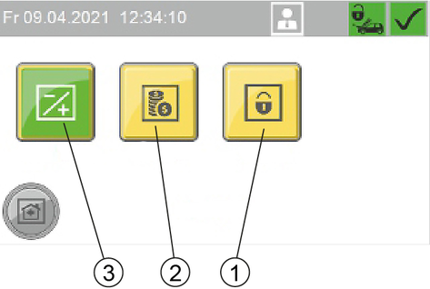
In the Machine menu, system parameters are set and the washing station can be locked.
In the Components menu, the temperature of the hot water can be set.
In the Coin value menu the wash value for 100% program run time and the coin values for the individual channels of the coin acceptor are set.
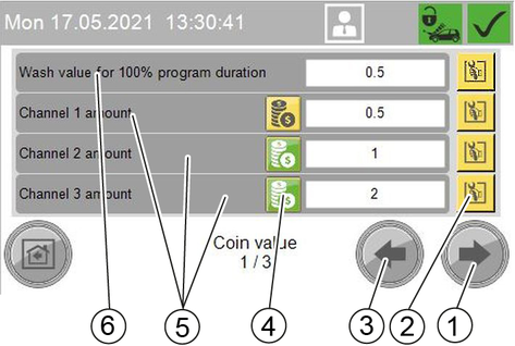
Channel ... amount: Channels of an electronic coin acceptor
External amount: Mechanical coin acceptor
External 1 amount: Payment system with RFID
Press the Setting button next to the desired value.
Enter the desired value.
In the Lock menu, the washing station is locked or unlocked.
The lock is effective regardless of the set opening hours.
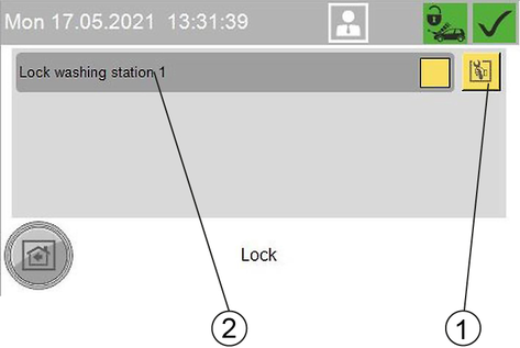
Press the Change Setting button.
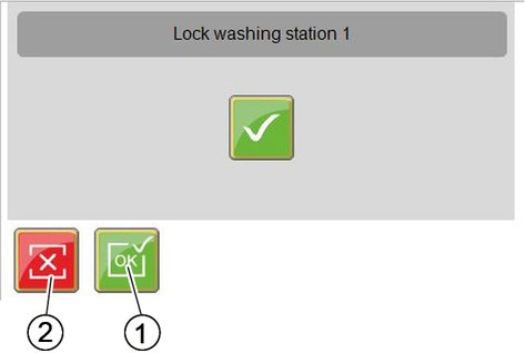
Press the desired button.
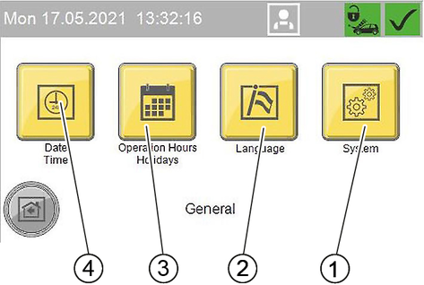
In the General menu, the time, date and operating times are set and the display language is selected.
The time, date and summer time are set in the Date Time menu.
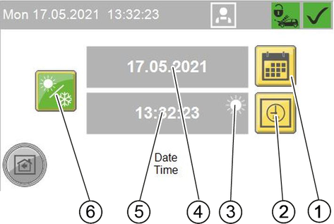
Setting the time
Press the Set Time button.
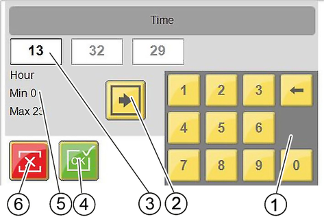
Use the Change Input Field button to select the desired input field.
Delete the field content with the delete key on the keyboard.
Enter the desired value with the keyboard.
Repeat the process until all desired changes have been made.
Exit the window.
The date is set according to the same principle as described for the time.
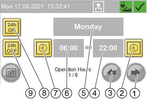
In the Operation Hours Holidays menu, the opening hours are defined for each weekday and for public holidays. Fixed and changing public holidays are also defined.
The setting is made according to the same principle as in the Date Timemenu.
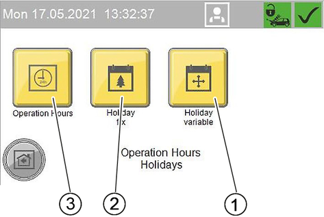
Menu Operation Hours
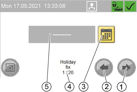
Menu Holiday fix
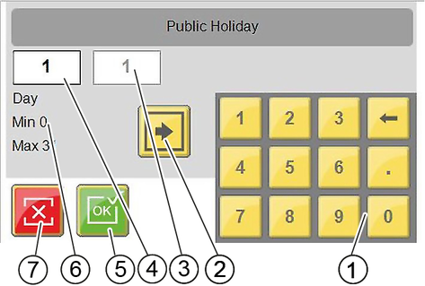
Fixed public holidays always occur on the same date each year.
Menu Holiday variable
Changing public holidays occur at a different date each year.
The setting is made in the same way as for Holiday fix, except that here the year must also be set.
This menu is used to select the language in which the display is shown.
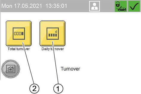
In the General Info menu, turnover, operating hours, maintenance information and fault messages can be viewed.
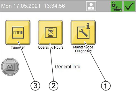
In the Turnover menu, the total turnover and daily turnover are displayed.
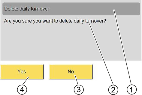
The daily turnover can be deleted.
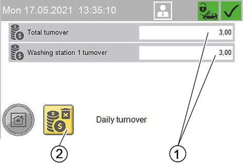
Daily turnover
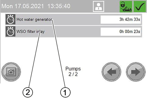
In the Operating Hours menu, the operating hours of individual system components and the individual washing programmes are displayed.
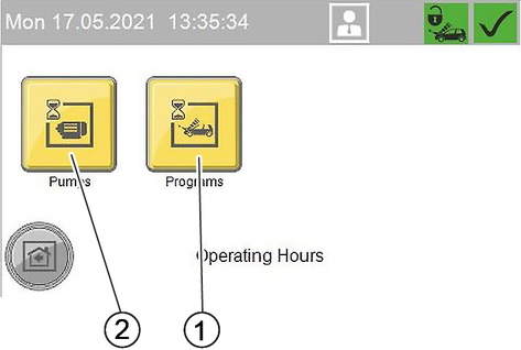
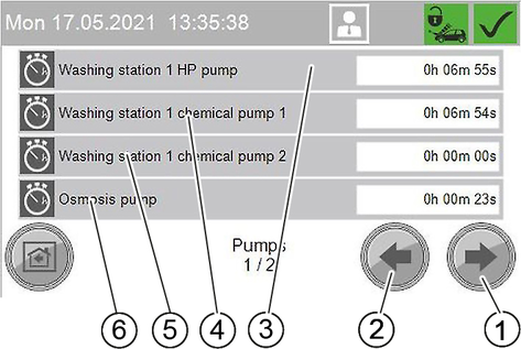
Operating hours of system components
The menu with the operating hours of the washing programmes is structured according to the same principle.
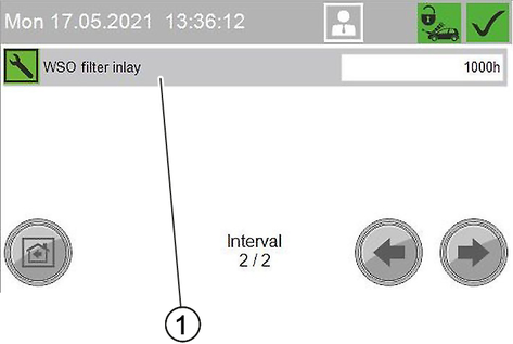
The Maintenance Diagnostic menu shows the times until the next maintenance, system information, error messages and events.
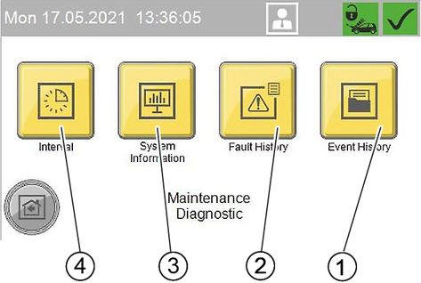
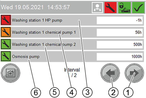
In the Interval menu, the time until the next maintenance is displayed for the individual system components.
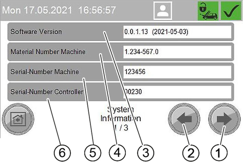
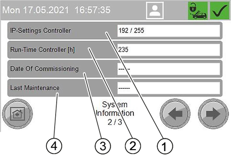
In the System Information menu, system data, settings of the control and operations data of the control are displayed.
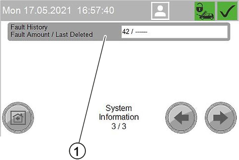
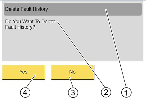
In the Fault History menu, the error messages since the last deletion of the fault memory are displayed.
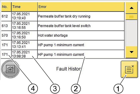
The Event History menu is structured in the same way as the Fault History menu.
The frost protection device consists of a hot air blower and antifreezing circulation or frost protection with lost water.
Note: The presence of a frost protection system ensures the following properties:
Restricted washing operation at temperatures below – 5 °C. In restricted washing operation the washing brush must be regularly checked for icing. Brush washing with an iced washing brush can damage the vehicle. If the washing brush is iced up, the washing brush must be disabled or, in the case of the 1-tool version, the combination spray lance must be replaced with a high-pressure spray lance. Please contact your Customer Service responsible if washing operation is to be extended to lower temperatures. At temperatures below –15 °C, washing makes no sense because an ice coating forms on the vehicle. This ice coating can even impair the function of important vehicle components. For this reason, you must lock the system at temperatures less than –15 °C.
Frost protection of the system down to –20 °C. At temperatures less than–20 °C the "Frost shutdown" procedure is to be performed.
Frost protection water running onto the washing station can lead to the formation of black ice under frosty conditions.
Insert the high-pressure gun into the brush chute after use.
Black ice on the washing station presents an increased danger of accidents.
Lock the washing station if there is a danger of black ice.
An uninterruptible power supply and water supply must be ensured. The water supply must be protected against frost.
Technically correct erection and installation of the system.
The hot air blower is set correctly.
All maintenance measures described in the "Maintenance and care" chapter have been performed.
All cleaning tools are placed back in the tool holders.
The high-pressure gun with frost protection bore belonging to the system is installed.
The hose line from the system to the cleaning tool has not been extended or replaced with a longer hose.
The temperatures stated above relate to the installation site. Temperatures stated in weather forecasts are secondary.
The hot air blower heats the interior of the system to provide frost protection.
Turn the performance controller to level "I".
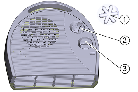
Adjust the thermostat controller according to the exterior temperature:
If the exterior temperature is higher than -10 °C, set the thermostat controller to the frost protection position.
If the exterior temperature is lower than -10 °C, set the thermostat controller to level "I".
Note: The frost protection device only works when the system is switched on and the door is closed. The trigger must therefore not be set to "0/OFF". The system power supply must not be interrupted either. Operation of the hot air blower is interrupted during operation of a high-pressure pump.
The hot air blower can overheat and cause a fire if the air inlets and air outlets are covered.
Never cover the air inlets and air outlets of the hot air blower.
The frost protection cannot be maintained in the event of a power failure.
Perform a frost protection shutdown in the case of a power failure.
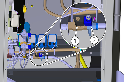
If there is a risk of frost, circulating water flows through the cleaning tools and their supply lines, thus protecting them from freezing.
The anti-freezing circulation circuit is placed in operation by the anti-freezing pump.
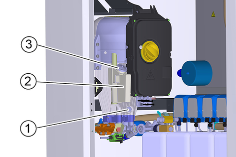
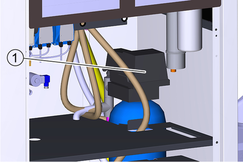
The following components show that the system is equipped with an antifreezing circulation:
If there is a risk of frost, fresh water flows through the cleaning tools and their supply lines, thus protecting them from freezing. The water is then discharged into the waste water system.
The presence of the frost protection solenoid valve indicates that the system is equipped with this frost protection version.
For a better overview, the maintenance work required to ensure correct operation of the frost protection system is summarised again here. To check the frost protection system, the work must also be performed annually before the frost period begins. The maintenance work described in the "Maintenance and care" chapter must also be performed in winter.
Time & date | Activity | Performed | By whom |
|---|---|---|---|
Before the frost period | Clean the frost protection pump filter. | Clean the filter and re-insert. | Operator |
Cleaning the filter in the Power foam nozzle (option) | Remove and clean the filter (see "Cleaning the Power foam nozzle filter"). Determine the following cleaning intervals according to experience. | Operator | |
Several times a day under frosty conditions | Check the washing brush | Check for dirt and ice and lock the brush cleaning if necessary. | Operator |
Daily under frosty conditions | Check the interior spaces of the system. | Is the hot air fan operating? Is the setting of the thermostat regulator correct (warmer than -10 °C - level "I", colder than -10 °C - level "II")? | Operator |
Daily during frost, only with frost protection circuit | Check the tool holders. | Is the frost protection float tank outlet free? | Operator |
Clean the sieve. | See the section "Care and maintenance/Cleaning the sieve". | Operator | |
Clean the frost protection pump filter. | Clean the filter and re-insert. | Operator | |
After 160 operating hours or monthly | Check the antifreeze water quantity | Minimum value: approx. 0.5 l/min per washing tool (the tool with the lowest flow is decisive). Water quantity smaller with frost protection circuit: Clean the frost protection pump filter, clean the sieve (on the frost protection ball tap), flush the line. Larger water quantity for all tools: Regulate the water quantity with the frost protection ball tap. Larger water quantity only at the high-pressure gun: Replace the node piece in the high-pressure gun. WARNINGThe high-pressure gun can move uncontrollably and cause injuries if the frost protection water quantity is too high. Be sure to replace the node piece in the high-pressure gun if the frost protection water quantity is too high. | Operator |
Unscrew the front part of the nozzle.
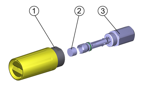
Remove and clean the filter.
Install the filter.
Screw the front part of the nozzle on to the nozzle holder and tighten it.
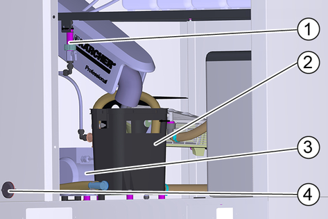
For disconnection from the water supply, the system is supplied with water from a float tank with downstream booster pump.
Turn the power switch to "0/OFF".
Shut down a system without frost protection (see "Shutting down" chapter).
For a system with frost protection:
Leave the trigger at position "1".
Lock the washing station in the "Washing" menu item of the control.
If there is no danger of frost during the shutdown period:
Close off the water supply.
Switch off the power supply.
Perform the following additional steps in the case of potential frost:
Empty all float containers.
Unscrew the hoses at the float containers and allow them to drain completely.
Unscrew the hoses from the high-pressure pump and allow the water to drain.
Unscrew the high-pressure hose from the pump head and allow the water to drain.
Remove the detergent canister and store it in a frost-protected place.
In case of doubt, have the maintenance performed by Customer Service.
Remove the RO membranes and store them in a frost-protected place.
Empty the permeate buffer tank.
Flush the system (without base exchanger) with antifreeze solution.
Rinse the base exchanger with concentrated salt solution.
Blow out all parts containing water with oil-free compressed air.
During longer breaks in operation, the system, with the exception of the base exchanger, must be flushed with antifreeze solution to protect it from corrosion.
In case of doubt, have the shutdown performed by Customer Service.
1 Only for water softening option
2 Only for reverse osmosis option
3 Only for high-pressure pump type 908
4 Only for frost protection option (all variants)
5 Only for 2-tool and 3-tool version
6 Only for 3-tool version
7 Only for frost protection circuit
8 Only for frost protection with waste water
9 Only for variants with mains isolation cat. 5
10 Only for variants without mains isolation
If the lever of the high-pressure gun is released, the circulation valve opens but the high-pressure pump remains in operation. The high-pressure jet is immediately available when the trigger gun is opened again.
The motor circuit breaker shuts off the device if power consumption is too high.
A winding protection contact is only installed in models with 900 l/h.
The winding protection contact in the motor winding of the pump drive sends a signal to the controller in the case of thermal overload. This switches the motor off.
The temperature sensor switches the electrical heating element on when the water temperature in the hot water float tank falls and switches it off again when the maximum temperature is reached.
The float switch in the hot water float tank switches the electrical heating element off if the water level is too low.
Prevents operation of the electric heating element when the hot water float tank is empty.
Only for systems with base exchanger.
If the residual hardness of the softened water exceeds a limit value, the control calculates the residual capacity of the base exchanger bottle.
Regeneration of the base exchanger bottle is started the following night at the latest.
Only for systems with reverse osmosis.
If there is water shortage, the system is stopped to prevent the RO pump from running dry.
Only for systems with reverse osmosis.
Switches off the RO pump when the permeate buffer tank is full.
Only for systems with reverse osmosis.
Switches on the RO pump when the permeate buffer tank is full.
Regular maintenance according to the following maintenance plan is fundamental for a safely operating system.
Use only original manufacturer spare parts or parts recommended by the original manufacturer, such as
Spare parts and wearing parts,
Accessories,
Operating materials,
Detergent.
Danger of death from electric shock.
Switch off the device at the on-site main trigger and secure against being switched on again before working on the device.
Allow only qualified electricians to work on electrical components of the system.
A high pressure water jet can escape from damaged parts and cause injuries.
Depressurise the system by turning the trigger to "0/OFF" and then opening the high-pressure gun until the pressure has been released from the system.
A high-pressure water jet can damage system components.
Do not clean the interior of the system with the high-pressure jet. When performing exterior cleaning, keep the high-pressure jet away from the upper section of the system (with coin slot, remaining value display and program switch).
Switch off the on-site main switch and secure it against being switched on again.
Disconnect the water supply.
Operator: Work labelled with "Operator" may only be performed by instructed persons capable of operating and maintaining high-pressure systems.
Customer Service: Work labelled with "Customer service" may only be performed by KÄRCHER customer service technicians or KÄRCHER-authorised technicians.
You can agree on regular safety inspections or close a maintenance contract with your dealer. Please seek advice on this.
WSO: Only carry out on systems with base exchanger
RO: Only carry out on systems with reverse osmosis.
Time & date | Activity | Performed | By whom |
|---|---|---|---|
Daily | Check the high-pressure hoses. | Examine the high-pressure hoses for mechanical damage such as abrasion damage, visible hose fabric, kinks and cracked rubber. Replace damage high-pressure hoses. | Operator |
Check the washing brush. | Check the washing brushes for damage, soiling and wear. Replace bristles that are shorter than 30 mm. In winter at temperatures below –5 °C, check for ice formation and lock the foam wash if necessary. Replace the combination spray lance with a high-pressure spray lance for this | Operator | |
Check the information notices at the washing station. | Check that the user information notices are present and legible. | Operator | |
Check the leak-tightness of the system. | Check pump and line system for leaks. Contact Customer Service when oil is present under the high-pressure pump or when more than 3 drops of water per minute escape from the high-pressure pump during operation. | Operator | |
Check the detergent filling level. | Check the filling level and refill if necessary. | Operator | |
Emptying the coin box | Open the appliance door and empty the coin box. | ||
For systems with frost protection: Daily in the case of frost | Check the frost protection devices. | Is the hot air fan operating? Is the setting of the thermostat regulator correct (warmer than -10 °C - level "I", colder than -10 °C - level "II")? Is the frost protection device operating (frost protection water quantity of approx. 0.5 l/min)? Is the tool holder drain opening free? | Operator |
Clean the sieve. | See the section "Cleaning the sieve". | Operator | |
Clean the frost protection pump filter. | Clean the filter and re-insert. | Operator | |
After 40 operating hours or weekly | Check the oil level of the high-pressure pump. | The oil level must lie between the MIN and MAX marks, otherwise refill with oil. | Operator |
Check the oil level. | Milky oil indicates water in the oil. Notify Customer Service. | Operator | |
Clean the tool holders. | Remove dirt from the tool holders. | Operator | |
Checking detergent filter | Visually check the high-pressure jet for the presence of detergent, clean detergent filter if necessary. | Operator | |
Check for correction function | Checking the functionality of all washing programs | Operator | |
WSO: Checking the salt tank | Is the salt level above the water level? Top up the softening salt if necessary. | Operator | |
WSO: Check the residual hardness of the softened water | Remove water from the hot water float tank and determine the residual hardness with test set B (order no. 6.768-003). Target value: Less than 3 °dH. | Operator | |
Cleaning the outside of the housing | Mix a 10% solution of the "Washing hall and tile cleaner RM 841" detergent, apply to the surfaces, allow to react for approx. 2 to 3 minutes, do not allow to dry. After the contact time, rinse thoroughly with the high-pressure jet. | Operator | |
Mix a 20 % solution of "Washing Hall and Tile Cleaner RM 841" detergent, apply to the surface and allow to react for approx. 2 to 3 minutes. After the contact time, clean the surfaces with a damp pad or microfibre cloth and then rinse thoroughly with a high-pressure jet. If desired, the large surfaces can be wiped off with a rubber squeegee. | Operator | ||
Cleaning the splash guard tarpaulins | Mix a 10% solution of the "Washing hall and tile cleaner RM 841" detergent, apply to the surfaces, allow to react for approx. 2 to 3 minutes, do not allow to dry. After the contact time, rinse thoroughly with the high-pressure jet. ATTENTIONRisk of damage Solvents and detergents containing solvents can damage the splash guard tarpaulins. Do not clean the splash guard tarpaulins with solvents or detergents containing solvents. | Operator | |
Once, 1 month after initial startup | WSO: Changing the WSO ultra-fine filter | Shut off the fresh water inlet, unscrew the filter cup, replace the filter insert, refit the new filter insert and filter cup, open the fresh water inlet. | Operator |
After 80 operating hours or fortnightly | Clean and care for the housing. | Thoroughly clean the exterior and interior of the housing. | Operator |
After 160 operating hours or monthly | Checking the frost protection water quantity. | Minimum value: approx. 0.5 l/min per washing tool (the tool with the lowest flow is decisive). Water quantity smaller with frost protection circuit: Clean the frost protection pump filter, clean the sieve (on the frost protection ball tap), flush the line. Larger water quantity for all tools: Regulate the water quantity with the frost protection ball tap. Larger water quantity only at the high-pressure gun: Replace the node piece in the high-pressure gun. WARNINGThe high-pressure gun can move uncontrollably and cause injuries if the frost protection water quantity is too high. Be sure to replace the node piece in the high-pressure gun if the frost protection water quantity is too high. | Operator |
Clean the detergent filters in the detergent containers. | Remove the filter and rinse thoroughly with clean water. | Operator | |
WSO: Checking the salt tank | Check the water level (approx. 5...25 cm above the sieve plate). | Operator | |
Check for deposits, empty if necessary, clean, refill with softening salt and put back into operation. Danger of malfunctions. When topping up with softening salt, use only the softening salt in tablet form listed in the chapter 'Accessories'. | Operator | ||
Lubricate the door hinges. | Lubricate the hinges with grease (order no.: 6.288-072). | Operator | |
Lubricate the locks for doors and control cabinet doors. | Spray care agent (order no.: 6.288-116) into the locks. | Operator | |
Quarter-yearly | Cleaning the coin slot | Open the device door. Clean the coin slot (see section "Maintenance work"). | Operator |
After 250 operating hours or half-yearly | Check the pump head. | Customer Service | |
Check the fresh water float valves. | If water escapes from the overflow hose, check the seal at the float valve. If necessary, replace the float valve. | Operator/Customer Service | |
Check the pump hose in the dosing pump. | Check the pump hose for cracks and wear and replace if necessary. | Operator/Customer Service | |
After 500 operating hours or annually | Completely check the high-pressure pumps. | Customer Service | |
Replace the oil in the high-pressure pump. | See Maintenance work. | Operator | |
Annually before the frost period | Cleaning the filter in the Power foam nozzle (option) | See "Cleaning the frost protection/Power foam nozzle". Determine the following cleaning intervals according to experience. | Operator |
Every 1000 operating hours | WSO: Changing the WSO ultra-fine filter | Shut off the fresh water inlet, unscrew the filter cup, replace the filter insert, refit the new filter insert and filter cup, open the fresh water inlet. | Operator |
Safety check | Safety check according to the directives for liquid jet cleaners/accident prevention guideline. | Customer Service |
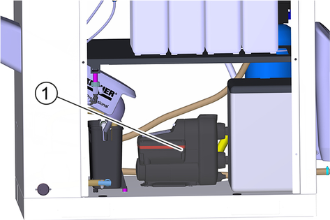
Danger of burns
The high-pressure pump and the engine oil are hot and cause burns if touched.
Allow the high-pressure pump to cool down for 15 minutes before changing the oil.
Place a suitable oil collection container under the oil drain plug.
Remove the oil tank cap.
Unscrew the oil drain screw and catch the escaping oil.
Screw in and tighten the oil drain screw.
Slowly fill with new oil until the "MAX" marking on the oil tank.
Fit the oil reservoir cap.
Dispose of the old oil in an environmentally friendly manner or hand it over to an authorised collection point.
Open the union nut.
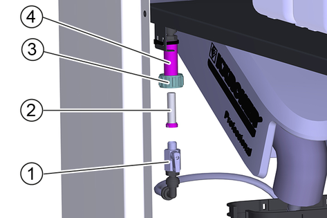
Pull the frost protection ball tap down,
Pull the sieve out of the holder and clean it.
Insert the sieve.
Fasten the frost protection ball tap to the holder with the union nut.
Open the device door.
Open the coin acceptor.
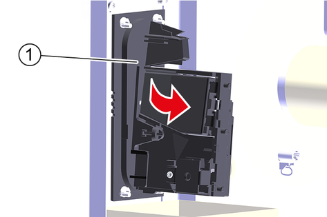
Clean the coin track with a damp cloth with washing-up liquid.
Remove the control button cover.
Press and hold the red button.
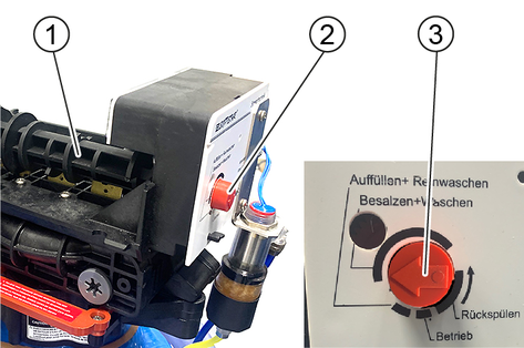
Turn the camshaft by hand until the arrow points to "Salting and washing".
The regeneration process starts and takes about 1 hour.
Risk of fatal injury from electric shock.
Switch off the device at the on-site main power switch and secure against being switched on again before working on the device.
A high-pressure water jet can escape from damaged parts and cause injuries.
Depressurise the system by turning the power switch to "0/OFF" and then open all high-pressure guns until the pressure has been released from the system.
Operator: Work labelled with "Operator" may only be performed by instructed persons capable of operating and maintaining high-pressure systems.
Qualified electrician: Work labelled with "Electrician" may only be performed by qualified electricians.
Customer Service: Work labelled with "Customer service" may only be performed by KÄRCHER customer service technicians or KÄRCHER-authorised technicians.
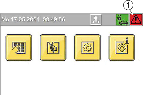
If there are critical faults, fault messages or events, the start screen automatically changes to the message view after approx. 1 minute.
An active message is indicated at the control by an attention symbol in the top right corner.
Message displays
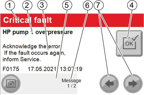
Red: critical fault; system stops immediately
yellow: Malfunction; system can continue operating
green: Event; information for the operator
If the button is greyed out, the fault still applies and cannot be acknowledged.
If the button has a yellow background, the malfunction has been rectified and the fault can be acknowledged.
The view switches to the next screen automatically after approx. 2-3 seconds. The progress bar has then finished.
If there is a critical fault, the system cannot be operated.
This is indicated by a red bar in the corresponding menu screen.
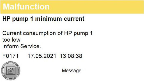
Malfunction display example
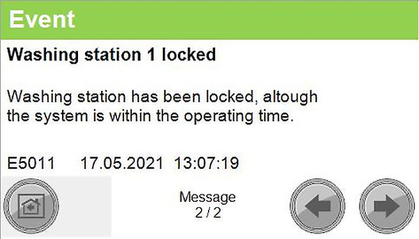
Event display example
Error number | Cause | Rectification |
|---|---|---|
F0003 | HP pump 1 connection. No CAN bus data connectionHP pump 1 | Inform Service |
F0004 | HP pump 1 overload. Output overload HP pump 1 | Inform Service |
F0005 | Remote control 1 connection. No CAN bus data connection Remote control 1 | Inform Service |
F0063 | A39 connection. No CAN bus data connection | Inform Service |
F0064 | A39 overload. Output overload A39 | Inform Service |
F0065 | A40 connection. No CAN bus data connection | Inform Service |
F0066 | A40 overload. Output overload A40 | Inform Service |
F0101 | Exterior temp sensor defective | Inform Service |
F0170 | HP pump 1 overcurrent. Current consumption of HP pump 1 too high. | Ackowledge fault. Inform Service if fault occurs again. |
F0171 | HP pump 1 minimum current. Current consumption of HP pump 1 too low | Inform Service |
F0172 | Relay / HP pump 1 contactor stuck. HP pump 1 electronics malfunction | Inform Service |
F0174 | HP pump 1 winding protect.contact | Ackowledge fault. Inform Service if fault occurs again. |
F0175 | HP pump 1 overpressure | Ackowledge fault. Inform Service if fault occurs again. |
F0176 | HP pump 1 oil level too low | Refill oil, Acknowledge malfunction |
F0190 | Coin reset remote control 1 | Inform Service |
F0191 | Coin signal remote control 1 | At mechanical coin acceptor check the microswitch |
F0570 | Hot water shortage | Check the hot water supply |
F0571 | Hot water overtemperature | Ackowledge fault. Inform Service if fault occurs again. |
F0572 | Hot water temperature sensor defective | Inform Service |
F0576 | No flow detected by flow monitor | Ackowledge fault. Inform Service if fault occurs again. |
F0577 | Flow monitor is defective | Ackowledge fault. Inform Service if fault occurs again. |
F0578 | Automatic hot water circuit-breaker | Reset automatic circuit-breaker |
F0610 | BA regeneration failed. Hardness sensor indicateshard water after regeneration. | Refill salt, acknowledge fault |
F0611 | BA regeneration failed. Regeneration of the bottle could not be started. | Inform Service |
F0612 | Permeate buffer tank dry running. Have the tank filled up to the empty buffer tank level switch (maximum switch-on delay of 15 minutes) | Have the tank filled up to the empty buffer tank level switch (maximum switch-on delay of 15 minutes) |
F0613 | Permeate buffer tank level switch. Empty and full buffer tank level switches switch simultaneously | check level switch. |
F0614 | Permeate buffer tank level switch. Empty and full buffer tank level switches switch simultaneously | check level switch. |
F0615 | Water softening no water pressure | Check the water supply |
F0616 | On-site water treatment system | Check on-site water treatment system |
F1125 | Controller Batterie Back-Up Batterie Of Controller Defective | Inform Service |
Malfunction | Possible cause | Rectification | By whom |
|---|---|---|---|
System does not come up to pressure or the pump knocks | Water supply volume too low. | Check the water supply volume (see the Technical data). | Operator |
High-pressure nozzle clogged or rinsed out. | Clean or replace the high-pressure nozzle. | Operator | |
Incorrect high-pressure nozzle installed. | Replace the high-pressure nozzle (for size see "Technical data"). | Operator | |
Line clogged. | Check that all lines are free. | Operator | |
System draws in air. | Check the system for leaks, detergent suction hose must be inserted into the detergent, refill the detergent container. | Operator | |
Check the pump hose for cracks and wear and replace if necessary. | Operator | ||
High-pressure pump leaking (more than 3 drops of water per minute) | Defective pump component. | Replace the defective component. | Customer Service |
Detergent not being sucked | Clogged filter or clogged hose. | Clean the parts. | Operator |
Defective check valve. | Replace the valve. | Customer Service | |
Pump hose in the dosing pump damaged. | Check the pump hose for cracks and wear and replace if necessary. | Operator, Customer Service | |
High-pressure pump sucking air | Detergent container empty. | Fill with detergent. | Operator |
Malfunction | Possible cause | Rectification | By whom |
|---|---|---|---|
Water shortage in the hot water float tank | Water inlet blocked. | Open the fresh water stop valve (on site). | Operator |
Float valve defective. | Check the float valve, repair it if necessary | Operator | |
Dry running sensor defective. | Check the sensor. | Operator | |
Hose burst or released. | Check hose lines, fasten or replace if necessary. | Operator | |
System disconnection pump (optional) not working. | Check the pump. Check the power supply of the pump. | Customer Service | |
Water temperature too high or too low | Hot water temperature sensor is defective. | Check the temperature sensor, replace it if necessary. | Customer Service |
Malfunction | Possible cause | Rectification | By whom |
|---|---|---|---|
The coin acceptor rejects all coins | Trigger switched off. | Turn the trigger (in the device) to "1". | Operator |
Time or operating times incorrectly set. | Check the settings at the control. | Operator | |
A critical fault has deactivated the system. | Check the control for critical faults. Rectify and acknowledge possible faults. | Operator | |
The coin acceptor is soiled. | Clean the coin slot (see "Care and maintenance"). | Operator |
Malfunction | Possible cause | Rectification | By whom |
|---|---|---|---|
Base exchanger does not regenerate | No power supply. | Check the power supply. | Operator |
Water remains hard after regeneration | Salt tank is empty. | Replenish softening salt, wait for the brine to form (approx. 2 hours), start manual regeneration. Never allow the salt level to fall below the water level in the salt tank. | Operator |
Brine is not drawn in | Water inlet pressure too low. | Increase the water inlet pressure to at least 0.3 MPa (3 bar). | Operator |
Malfunction | Possible cause | Rectification | By whom |
|---|---|---|---|
RO pump does not start | Permeate buffer tank is full. | Wait until permeate is consumed. | Operator |
The start-up time of the control is not yet finished. | Wait. | Operator | |
Water shortage. | Check the ultra-fine filter for contamination, replace the filter inlay if necessary. | Operator | |
Base exchanger regeneration running. | Wait for the end of the regeneration. | Operator | |
No softened water comes from the base exchanger. | Check the base exchanger. | Operator | |
The permeate buffer tank is frequently empty | Water supply temperature too low. | Check the temperature of the softened water. | Operator |
Malfunction | Possible cause | Rectification | By whom |
|---|---|---|---|
Hot air blower not in operation | Hot air blower incorrectly adjusted. | Check the settings of the hot air blower (see "Frost protection/hot air blower"). | Operator |
Frost protection not in operation | Voltage supply has been interrupted. | Check and ensure the power supply. | Operator |
Cleaning tools frozen. | Frost protection pump filter or sieve clogged (antifreezing circulation only) | Open and clean the frost protection pump filter. Clean the sieve (see "Care and maintenance/Cleaning the sieve"). | Operator |
Country variant | |
Country | EU |
Electrical connection | |
Mains voltage | 400 V |
Phase | 3 ~ |
Frequency | 50 Hz |
Connected load without frost protection | 8,7 kW |
Connected load, with frost protection | 11,5 kW |
Degree of protection | IPX5 |
Power protection (slow-blowing) | 32 A |
Residual current device | 0,03 delta I, A |
Water connection | |
Feed pressure | 0,6 MPa |
Input temperature (max.) | 40 °C |
Input amount (min.) | 10 l/min |
Device performance data | |
Nozzle size of standard nozzle | 5004 -- |
Operating pressure | 10 MPa |
Operating pressure (max.) | 11 MPa |
Water flow rate | 9,16 l/min |
Hot water temperature during continuous operation | 25 °C |
High-pressure gun recoil force | 17 N |
Detergent flow rate | 2,5...70 ml/min |
Dimensions and weights | |
Length x width x height maximum | 800x1200x2100 mm |
Space for detergent canister | 4x10 l |
Cold water float tank | 3,5 l |
Hot water float tank | 30 l |
Weight | 330 kg |
Oil quantity of a high-pressure pump | 0,5 l |
Oil type | SAE 90 Type |
Determined values in acc. with EN 60335-2-79 | |
Hand-arm vibration value | 0,2 m/s2 |
Uncertainty K | 0,5 m/s2 |
Sound pressure level | 66 dB(A) |
Uncertainty KpA | 3 dB(A) |
Sound power level LWA + uncertainty KWA | 85 dB(A) |
Base exchanger | |
Capacity BA 42 | 42 °dH/m3 |
Capacity BA 65 | 65 °dH/m3 |
Water hardness of softened water | 0...0,3 °dH |
Salt tank | 35 l |
Reverseosmosis | |
Permeate capacity, min. at 15 °C water temperature | 60 l/h |
Operating pressure in new condition at 15 °C water temperature | 1,4 (14) MPa (bar) |
Desalination rate | 98...99 % |
Water temperature range | 2...30 °C |
Ambient temperature (max.) | 40 °C |
Residual hardness of supply water | 0...0,3 °dH |
Maximum permeate conductivity for spotless drying | <100 µS/cm |
Permeate buffer tank | 65 l |
Country variant | |
Country | EU |
Electrical connection | |
Mains voltage | 400 V |
Phase | 3 ~ |
Frequency | 50 Hz |
Connected load without frost protection | 14,7 kW |
Connected load, with frost protection | 17,5 kW |
Degree of protection | IPX5 |
Power protection (slow-blowing) | 40 A |
Residual current device | 0,03 delta I, A |
Water connection | |
Feed pressure | 0,6 MPa |
Input temperature (max.) | 40 °C |
Input amount (min.) | 10 l/min |
Device performance data | |
Nozzle size of standard nozzle | 5004 -- |
Operating pressure | 10 MPa |
Operating pressure (max.) | 11 MPa |
Water flow rate | 9,16 l/min |
Hot water temperature during continuous operation | 60 °C |
High-pressure gun recoil force | 17 N |
Detergent flow rate | 2,5...70 ml/min |
Dimensions and weights | |
Length x width x height maximum | 800x1200x2100 mm |
Space for detergent canister | 4x10 l |
Cold water float tank | 3,5 l |
Hot water float tank | 30 l |
Weight | 330 kg |
Oil quantity of a high-pressure pump | 0,5 l |
Oil type | SAE 90 Type |
Determined values in acc. with EN 60335-2-79 | |
Hand-arm vibration value | 0,2 m/s2 |
Uncertainty K | 0,5 m/s2 |
Sound pressure level | 66 dB(A) |
Uncertainty KpA | 3 dB(A) |
Sound power level LWA + uncertainty KWA | 85 dB(A) |
Base exchanger | |
Capacity BA 42 | 42 °dH/m3 |
Capacity BA 65 | 65 °dH/m3 |
Water hardness of softened water | 0...0,3 °dH |
Salt tank | 35 l |
Reverseosmosis | |
Permeate capacity, min. at 15 °C water temperature | 60 l/h |
Operating pressure in new condition at 15 °C water temperature | 1,4 (14) MPa (bar) |
Desalination rate | 98...99 % |
Water temperature range | 2...30 °C |
Ambient temperature (max.) | 40 °C |
Residual hardness of supply water | 0...0,3 °dH |
Maximum permeate conductivity for spotless drying | <100 µS/cm |
Permeate buffer tank | 65 l |
Country variant | |
Country | EU |
Electrical connection | |
Mains voltage | 400 V |
Phase | 3 ~ |
Frequency | 50 Hz |
Connected load without frost protection | 26,7 kW |
Connected load, with frost protection | 29,5 kW |
Degree of protection | IPX5 |
Power protection (slow-blowing) | 63 A |
Residual current device | 0,03 delta I, A |
Water connection | |
Feed pressure | 0,6 MPa |
Input temperature (max.) | 40 °C |
Input amount (min.) | 10 l/min |
Device performance data | |
Nozzle size of standard nozzle | 5004 -- |
Operating pressure | 10 MPa |
Operating pressure (max.) | 11 MPa |
Water flow rate | 9,16 l/min |
Hot water temperature during continuous operation | 60 °C |
High-pressure gun recoil force | 17 N |
Detergent flow rate | 2,5...70 ml/min |
Dimensions and weights | |
Length x width x height maximum | 800x1200x2100 mm |
Space for detergent canister | 4x10 l |
Cold water float tank | 3,5 l |
Hot water float tank | 30 l |
Weight | 330 kg |
Oil quantity of a high-pressure pump | 0,5 l |
Oil type | SAE 90 Type |
Determined values in acc. with EN 60335-2-79 | |
Hand-arm vibration value | 0,2 m/s2 |
Uncertainty K | 0,5 m/s2 |
Sound pressure level | 66 dB(A) |
Uncertainty KpA | 3 dB(A) |
Sound power level LWA + uncertainty KWA | 85 dB(A) |
Base exchanger | |
Capacity BA 42 | 42 °dH/m3 |
Capacity BA 65 | 65 °dH/m3 |
Water hardness of softened water | 0...0,3 °dH |
Salt tank | 35 l |
Reverseosmosis | |
Permeate capacity, min. at 15 °C water temperature | 60 l/h |
Operating pressure in new condition at 15 °C water temperature | 1,4 (14) MPa (bar) |
Desalination rate | 98...99 % |
Water temperature range | 2...30 °C |
Ambient temperature (max.) | 40 °C |
Residual hardness of supply water | 0...0,3 °dH |
Maximum permeate conductivity for spotless drying | <100 µS/cm |
Permeate buffer tank | 65 l |
Country variant | |
Country | EU |
Electrical connection | |
Mains voltage | 400 V |
Phase | 3 ~ |
Frequency | 50 Hz |
Connected load without frost protection | 9,5 kW |
Connected load, with frost protection | 12,3 kW |
Degree of protection | IPX5 |
Power protection (slow-blowing) | 32 A |
Residual current device | 0,03 delta I, A |
Water connection | |
Feed pressure | 0,6 MPa |
Input temperature (max.) | 40 °C |
Input amount (min.) | 15 l/min |
Device performance data | |
Nozzle size of standard nozzle | 5004 -- |
Operating pressure | 10 MPa |
Operating pressure (max.) | 11 MPa |
Water flow rate | 9,16 l/min |
Hot water temperature during continuous operation | 20 °C |
High-pressure gun recoil force | 29 N |
Detergent flow rate | 2,5...70 ml/min |
Dimensions and weights | |
Length x width x height maximum | 800x1200x2100 mm |
Space for detergent canister | 4x10 l |
Cold water float tank | 3,5 l |
Hot water float tank | 30 l |
Weight | 330 kg |
Oil quantity of a high-pressure pump | 0,5 l |
Oil type | SAE 90 Type |
Determined values in acc. with EN 60335-2-79 | |
Hand-arm vibration value | 0,2 m/s2 |
Uncertainty K | 0,5 m/s2 |
Sound pressure level | 66 dB(A) |
Uncertainty KpA | 3 dB(A) |
Sound power level LWA + uncertainty KWA | 85 dB(A) |
Base exchanger | |
Capacity BA 42 | - °dH/m3 |
Capacity BA 65 | 65 °dH/m3 |
Water hardness of softened water | 0...0,3 °dH |
Salt tank | 35 l |
Reverseosmosis | |
Permeate capacity, min. at 15 °C water temperature | 60 l/h |
Operating pressure in new condition at 15 °C water temperature | 1,4 (14) MPa (bar) |
Desalination rate | 98...99 % |
Water temperature range | 2...30 °C |
Ambient temperature (max.) | 40 °C |
Residual hardness of supply water | 0...0,3 °dH |
Maximum permeate conductivity for spotless drying | <100 µS/cm |
Permeate buffer tank | 65 l |
Country variant | |
Country | EU |
Electrical connection | |
Mains voltage | 400 V |
Phase | 3 ~ |
Frequency | 50 Hz |
Connected load without frost protection | 15,5 kW |
Connected load, with frost protection | 18,3 kW |
Degree of protection | IPX5 |
Power protection (slow-blowing) | 40 A |
Residual current device | 0,03 delta I, A |
Water connection | |
Feed pressure | 0,6 MPa |
Input temperature (max.) | 40 °C |
Input amount (min.) | 15 l/min |
Device performance data | |
Nozzle size of standard nozzle | 5004 -- |
Operating pressure | 10 MPa |
Operating pressure (max.) | 11 MPa |
Water flow rate | 9,16 l/min |
Hot water temperature during continuous operation | 40 °C |
High-pressure gun recoil force | 29 N |
Detergent flow rate | 2,5...70 ml/min |
Dimensions and weights | |
Length x width x height maximum | 800x1200x2100 mm |
Space for detergent canister | 4x10 l |
Cold water float tank | 3,5 l |
Hot water float tank | 30 l |
Weight | 330 kg |
Oil quantity of a high-pressure pump | 0,5 l |
Oil type | SAE 90 Type |
Determined values in acc. with EN 60335-2-79 | |
Hand-arm vibration value | 0,2 m/s2 |
Uncertainty K | 0,5 m/s2 |
Sound pressure level | 66 dB(A) |
Uncertainty KpA | 3 dB(A) |
Sound power level LWA + uncertainty KWA | 85 dB(A) |
Base exchanger | |
Capacity BA 42 | - °dH/m3 |
Capacity BA 65 | 65 °dH/m3 |
Water hardness of softened water | 0...0,3 °dH |
Salt tank | 35 l |
Reverseosmosis | |
Permeate capacity, min. at 15 °C water temperature | 60 l/h |
Operating pressure in new condition at 15 °C water temperature | 1,4 (14) MPa (bar) |
Desalination rate | 98...99 % |
Water temperature range | 2...30 °C |
Ambient temperature (max.) | 40 °C |
Residual hardness of supply water | 0...0,3 °dH |
Maximum permeate conductivity for spotless drying | <100 µS/cm |
Permeate buffer tank | 65 l |
Country variant | |
Country | EU |
Electrical connection | |
Mains voltage | 400 V |
Phase | 3 ~ |
Frequency | 50 Hz |
Connected load without frost protection | 27,5 kW |
Connected load, with frost protection | 30,3 kW |
Degree of protection | IPX5 |
Power protection (slow-blowing) | 63 A |
Residual current device | 0,03 delta I, A |
Water connection | |
Feed pressure | 0,6 MPa |
Input temperature (max.) | 40 °C |
Input amount (min.) | 15 l/min |
Device performance data | |
Nozzle size of standard nozzle | 5004 -- |
Operating pressure | 10 MPa |
Operating pressure (max.) | 11 MPa |
Water flow rate | 9,16 l/min |
Hot water temperature during continuous operation | 50 °C |
High-pressure gun recoil force | 29 N |
Detergent flow rate | 2,5...70 ml/min |
Dimensions and weights | |
Length x width x height maximum | 800x1200x2100 mm |
Space for detergent canister | 4x10 l |
Cold water float tank | 3,5 l |
Hot water float tank | 30 l |
Weight | 330 kg |
Oil quantity of a high-pressure pump | 0,5 l |
Oil type | SAE 90 Type |
Determined values in acc. with EN 60335-2-79 | |
Hand-arm vibration value | 0,2 m/s2 |
Uncertainty K | 0,5 m/s2 |
Sound pressure level | 66 dB(A) |
Uncertainty KpA | 3 dB(A) |
Sound power level LWA + uncertainty KWA | 85 dB(A) |
Base exchanger | |
Capacity BA 42 | - °dH/m3 |
Capacity BA 65 | 65 °dH/m3 |
Water hardness of softened water | 0...0,3 °dH |
Salt tank | 35 l |
Reverseosmosis | |
Permeate capacity, min. at 15 °C water temperature | 60 l/h |
Operating pressure in new condition at 15 °C water temperature | 1,4 (14) MPa (bar) |
Desalination rate | 98...99 % |
Water temperature range | 2...30 °C |
Ambient temperature (max.) | 40 °C |
Residual hardness of supply water | 0...0,3 °dH |
Maximum permeate conductivity for spotless drying | <100 µS/cm |
Permeate buffer tank | 65 l |
The warranty conditions issued by our sales company responsible apply in all countries. We shall remedy possible malfunctions on your device within the warranty period free of cost, provided that a material or manufacturing defect is the cause. In a warranty case, please contact your dealer (with the purchase receipt) or the next authorised customer service site.
You can find more detailed information at: www.kaercher.com/dealersearch
Risk of injury, risk of damage
Be aware of the weight of the device during transportation.
When transporting in vehicles, secure the device against slipping and tipping over according to the applicable guidelines.
Risk of injury and damage
Be aware of the weight of the device during storage.
Only use original accessories and original spare parts. They ensure that the appliance will run fault-free and safely.
Information on accessories and spare parts can be found at www.kaercher.com.
EU Declaration of Conformity |
We hereby declare that the machine described below complies with the relevant basic safety and health requirements in the EU Directives, both in its basic design and construction as well as in the version placed in circulation by us. This declaration is invalidated by any changes made to the machine that are not approved by us.
Product: High-pressure cleaner
Type: 1.319-xxx
Currently applicable EU Directives2000/14/EC
2014/30/EU
2006/42/EC (+2009/127/EC)
2011/65/EU
2009/125/EC
Commission Regulation(s)(EU) 2019/1781
Harmonised standards usedEN 60335-1
EN 60335-2-79
EN IEC 63000: 2018
EN 55014-1: 2017 + A11: 2020
EN 55014-2: 2015
EN 61000-3-2: 2014
EN 61000-3-3: 2013
EN 62233: 2008
Applied conformity evaluation method2000/14/EG: Annex V
Sound power level dB(A)1-station version
Measured: 82
Guaranteed: 85
2-Platz
Measured: 81
Guaranteed: 83
The signatories act on behalf of and with the authority of the company management.

Documentation supervisor:
S. Reiser
Alfred Kärcher SE & Co. KG
Alfred-Kärcher-Str. 28 - 40
71364 Winnenden (Germany)
Ph.: +49 7195 14-0
Fax: +49 7195 14-2212
Winnenden, 2021/06/01
Declaration of Conformity (UK) |
We hereby declare that the product described below complies with the relevant provisions of the following UK Regulations, both in its basic design and construction as well as in the version put into circulation by us. This declaration shall cease to be valid if the product is modified without our prior approval.
Product: High-pressure cleaner
Type: 1.319-xxx
Currently applicable UK RegulationsS.I. 2001/1701 (as amended)
S.I. 2016/1091 (as amended)
S.I. 2008/1597 (as amended)
S.I. 2012/3032 (as amended)
S.I. 2010/2617 (as amended)
Commission Regulation(s)(EU) 2019/1781
Designated standards usedEN 60335-1
EN 60335-2-79
EN IEC 63000: 2018
EN 55014-1: 2017 + A11: 2020
EN 55014-2: 2015
EN 61000-3-2: 2014
EN 61000-3-3: 2013
EN 62233: 2008
Applied conformity assessment procedureS.I. 2001/1701 (as amended): Schedule 8
Sound power level dB(A)1-Platz
Measured: 82
Guaranteed: 85
2-Platz
Measured: 81
Guaranteed: 83
The signatories act on behalf of and with the authority of the company management.
Documentation supervisor:
S. Reiser
Alfred Kärcher SE & Co. KG
Alfred-Kärcher-Str. 28 - 40
71364 Winnenden (Germany)
Ph.: +49 7195 14-0
Fax: +49 7195 14-2212
Winnenden, 2021/06/01