HDS 9/50 De Tr1HDS 13/35 De Tr1HDS 13/20 De Tr1HDS 17/20 De Tr1
59696890 (02/25)
59696890 (02/25)
 Read these original operating instructions before using your device for the first time, follow them accordingly and keep them for later use or for future owners.
Notify the dealer immediately in the case of shipping damage.
Check package content when unpacking.
Be sure to read the safety instructions no. 5.951-949.0 prior to the initial startup!
 The packing materials can be recycled. Please dispose of packaging in accordance with the environmental regulations.
 Electrical and electronic devices contain valuable, recyclable materials and often components such as batteries, rechargeable batteries or oil, which - if handled or disposed of incorrectly - can pose a potential danger to human health and the environment. However, these components are required for the correct operation of the device. Devices marked by this symbol are not allowed to be disposed of together with the household rubbish.
Current information on content materials can be found at: www.kaercher.de/REACH
Please do not allow engine oil, heating oil, diesel and petrol to enter the environment. Please protect the ground and dispose of old oil in an environmentally friendly manner.
 | Do not point the high-pressure jet at people, animals, live electrical equipment or at the device itself. Protect the device from frost. |
 | Danger of injury from electrical voltage. Only qualified electricians or authorised and qualified technical specialists are permitted to work on the electrical systems. |
 | Warning of risk of crushing! |
 | Risk of eye and hearing damage. Wear eye and hearing protection. |
 | Health risk from poisonous exhaust gases. Never inhale the exhaust gases. |
 | Risk of burns from hot surfaces. |
Only applies to Germany: The device is only intended for mobile (not stationary) operation.
The device is used especially at locations where there is no electrical connection and it is necessary to work with hot water.
Cleaning of: Machines, Vehicles, Structures, Tools, Facades, Terraces, Gardening tools, etc.
Risk of injury!
When using at petrol stations or other hazardous areas
Please adhere to the respective safety instructions.Please do not let mineral oil contaminated waste water reach soil, water or the sewage system. Therefore, perform motor wash and undercarriage wash only on specified places with an oil separator
Dirty water
Premature wear and tear or deposits in the device
Supply the device using only clean water, or recycled water that does not exceed the specified limit values.The following limit values apply to the water supply:
ph-value | 6,5-9,5 |
| electrical conductivity | Conductivity of fresh water +1200 µS/cm |
settleable solids ** | < 0,5 mg/l |
total suspended solids *** | < 50 mg/l |
Hydrocarbons | < 20 mg/l |
Chloride | < 300 mg/l |
Sulphate | < 240 mg/l |
Calcium | < 200 mg/l |
Total hardness | < 28 °dH< 50 °TH< 500 ppm (mg CaCO3/l) |
Iron | < 0,5 mg/l |
Manganese | < 0,05 mg/l |
Copper | < 2 mg/l |
Active chloride | < 0,3 mg/l |
Free of unpleasant odours | |
* Maximum total of 2000 µS/cm** Sample volume 1 l, settling time 30 min*** No abrasive substances | |
Never operate the device in confined spaces.
Do not store, spill or use diesel fuel near open flames or appliances such as stoves, heating boilers, water heaters, etc., that have pilot lights or can produce sparks.
Never overfill the fuel tank.
Observe the respectively applicable national regulations for liquid jet cleaners.
Observe the respectively applicable accident prevention regulations. Liquid jet cleaners must be tested regularly and the results of the test recorded in writing.
The heating system of the device is a combustion system and must be checked regularly in accordance with the relevant national legal regulations.
Only applies to devices with vapour mode attachment kit: According to the applicable national regulations, this high-pressure cleaner must be initially commissioned by a qualified person when used commercially. KÄRCHER has already performed and documented this initial commissioning for you. You can request the documentation for this from your KÄRCHER partner. Please have the part and plant number of the device available when enquiring about the documentation.
Only applies to devices with vapour mode attachment kit: We explicitly state that the application national regulations require that this device must be inspected regularly by a qualified person. Please contact your KÄRCHER partner for this.
No changes may be made to the device or accessories.
Danger of accident
Tyres can come loose at high speed.
On vehicles authorised for 100 km/h: Tyres must not be older than six years. In the event of damage, dents/cracks on the side wall, tread separation etc., the tyres must be replaced immediately.Risk of injury!
Use only original high-pressure hoses.
The high-pressure hose and the spray unit must be suitable for use at the maximum operating pressure specified in the technical data.
Avoid contact with chemicals.
Check the high-pressure hose daily. Do not continue using kinked hoses. Do not continue using the high-pressure hose if the outer wire mesh layer is visible.
Do not continue using the high-pressure hose with a damaged thread.
Lay the high-pressure hose in such a way that it cannot be driven over.
A hose that has been driven over, kinked or subjected to impacts may no longer be used, even if no damage is visible.
Store the high-pressure hose in such a way that it is not subjected to any mechanical loads.
The high pressure pump is driven by an intermediate transmission by a diesel engine.
Between the float container and the high-pressure pump, the water is heated via a heat exchanger located in the motor's cooling circuit.
When the jet operation is interrupted, the overflow valve switches to pressure-free water circulation and the motor continues running at idle speed.
The water is heated by a pressure-side burner with oil firing.
During hot water operation, softening agents are added to the water.
HDS 9/50, HDS 13/35 only (optional with HDS 13/20, HDS 17/20): The operating pressure can be selected via the speed control of the motor.
HDS 13/20, HDS 17/20 only: The high-pressure pump draws detergent. The proportion of detergent in the water can be adjusted using a dosing valve.
HDS 13/20, HDS 17/20 only (option): Attachment kit for removing weeds with hot water.
HDS 13/20, HDS 17/20 only (option): Attachment kit for cleaning and disinfection with steam.
Safety devices protect the user and may not be disabled or functionally circumvented.
For immediate shut down of all functions: Press the Emergency Stop switch.
The device can only be put into operation if the front cover is closed.
If the front cover is opened during operation, the device shuts down and the indicator light front cover/emergency stop is red.
If the trigger gun is closed, the overflow valve opens and the high-pressure pump leads the water back into the float container. This prevents the maximum permissible working pressure from being exceeded.
HDS 13/20, HDS 17/20 only: When the water quantity is reduced via the pressure/quantity control on the trigger gun, the overflow valve opens and part of the water flows into the float container or the water reservoirs (depending on the position of the ball tap return flow valve).
The overflow valve is set and sealed at the factory. Setting must only be performed by Customer Service.
The safety valve opens if the overflow valve or pressure switch is faulty.
The safety valve is adjusted and sealed at the factory. The adjustment is performed only by customer service.
If the charging current of the alternator is insufficient during the charging process of the battery, the device shuts down.
Display malfunction: ERROR 1
If the water inlet temperature exceeds the maximum permissible temperature, the device shuts down.
If the cooling water temperature exceeds the maximum admissible temperature, the device shuts down.
Display malfunction: ERROR 3
The water shortage safeguard prevents the motor from being switched on in case of a water shortage.
Display malfunction: ERROR 4
Display malfunction: ERROR 5
Display malfunction: ERROR 5
The device can be operated for another 5 minutes until the fuel tank is completely empty by switching the device off and then on again.
The device shuts down if the fuel sensor is defective.
Display malfunction: ERROR 6
Display malfunction: ERROR 7
The exhaust gas thermostat switches off the burner when the exhaust gas temperature is too high.
Display malfunction: ERROR 9
If the water temperature at the burner outlet exceeds the maximum admissible temperature, the device switches off the burner.
The device switches off the burner if the temperature sensor is defective.
Display malfunction: ERROR 10
The flame monitoring switches off the burner in case of a burner fault.
Display malfunction: ERROR 11 or 12
If the standby time or the continuous operation time of 45 minutes is exceeded, the electronics switch the device off (factory setting).
Display malfunction: ERROR 14 or 15
The safety latch on the trigger gun prevents the device from being switched on unintentionally.
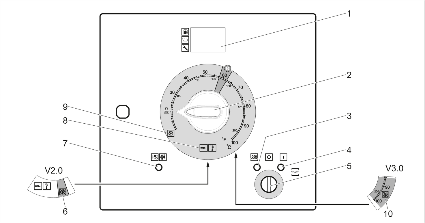
0/OFF = off
The authorisation documents for the device are stored in the electrical device cabinet. The cabinet is locked for transport.
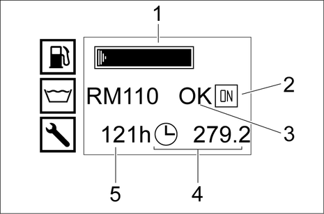
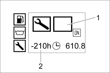
The display of the detergent tank is only present if the detergent tank has been detected as full once before.
In normal operation, the controller display alternates between the following displays:
Normal operation
Service: Due service tasks to be performed by the customer service (see care and service).
If multiple maintenance work is due, these are displayed one after another.
This display is not shown if no maintenance work is due.
Fault: Malfunction occurred (see Troubleshooting).
If several faults have occurred, these are displayed one after another.
This display is not shown if no faults are present.
Risk of injury!
Appliance, accessories, supply lines and connections must be in fault-free condition.
If they are not in a perfect condition, the device must not be used.Overheating of the device
Avoid overheating the device.
Ensure that the installation site is sufficiently ventilated.Risk of malfunctions and damage to the device.
The device must be in a horizontal position during operation.
Choose the installation site in a way that the exhaust gas opening is not covered.
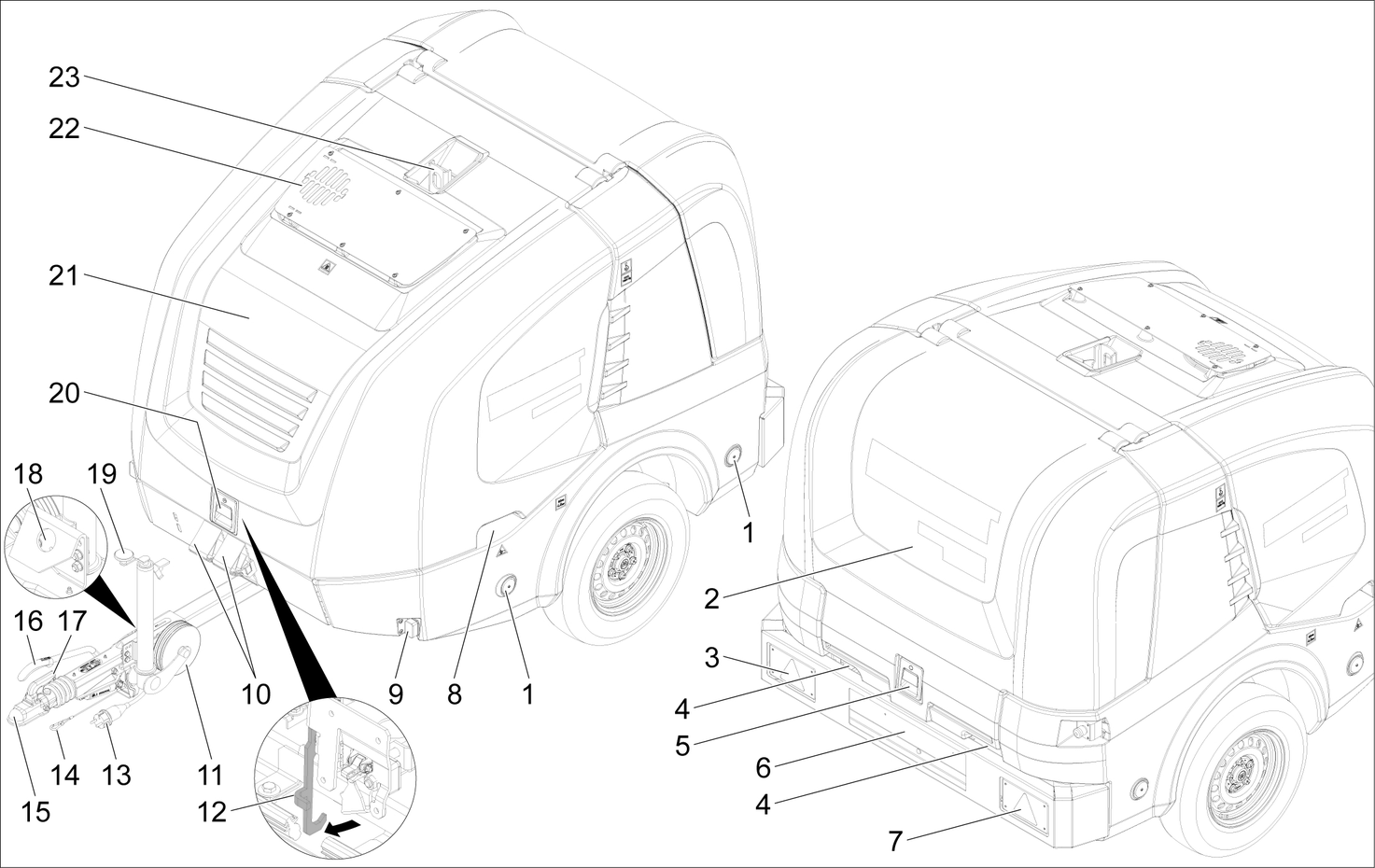
Lock parking brake.
Lower the support wheel by means of the crank.
Remove the tear-off rope from the towing vehicle.
Disconnect the socket plug connection from the vehicle lighting and insert it into the plug storage on the drawbar.
Secure the device with wheel chocks to prevent it from rolling away.
Disconnect the towing vehicle.
Align the device level using the support wheel.
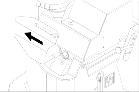
Actuate the front cover lock.
Front cover opens slightly.
Release the hook catch by pulling it out.
The front cover is swung up automatically.
When closing, make sure the hook catch engages.
Check the oil level of the motor. Do not start up the device if the oil level is below the "MIN" mark.
Top up with oil if necessary. (see Care and service)
Check the oil level at the oil-level gauge of the intermediate gearbox.
Top up with oil if necessary. (see Care and service)
Check the oil level on the oil tank or the oil dipstick of the high-pressure pump.
Top up with oil if necessary. (see Care and service)
Check the fill level of the coolant in the equalisation container of the motor coolant with a cooled off motor. The fluid level has to be between MIN and MAX.
Top up with coolant if necessary. (see Care and service)
Check the antifreeze concentration in the expansion tank.
Top up with antifreeze if necessary. (see Care and service)
Check the air filter.
Clean/replace the air filter if necessary. (see Care and service)
The liquid softener highly effectively prevents the calcification of the heating coil during operation with hard tap water. This is drip-fed dosed into the float container.
The dosage is set to medium water hardness at the factory.
A test container of liquid softener is included in the scope of delivery.
Open filling hole for liquid softener.
Fill up the liquid softener.
Close filling hole for liquid softener.
Unsuitable fuel
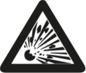
Risk of explosion
Only use diesel fuel or light heating oil. Unsuitable fuels, such as petrol, must not be used.When biodiesel B5 (as per EN 14214 - European Standard) is used, no special operating, service and maintenance conditions need to be observed.
When biodiesel B6 to B20 (as per EN 14214 - European Standard) is used, modification measures of the diesel engine are required. Moreover, special operating, service and maintenance conditions must be observed. Please contact an authorised Yanmar dealer.
Open the tank cap.
Fill in diesel fuel via the filling nozzle of the fuel tank.
Close the tank cap.
Wipe away spilled diesel fuel.
HDS 13/20, HDS 17/20 only:
Unsuitable detergents
Risk of injury
Use only KÄRCHER products.Never fill with solvents (e.g. petrol, acetone, thinners).Avoid contact with eyes and skin.Observe the safety and handling instructions of the detergent manufacturer.Kärcher offers an individual range of cleaning and care products. Your dealer will be happy to advise you.
Refill/replace the detergent.
As standard, the device is equipped with a maintenance-free battery.
Be sure to observe the following warnings when handling the batteries:
 | Observe the notes on the battery, in the instructions and in the vehicle operating instructions! |
 | Wear eye protection! |
 | Keep acids and batteries away from children. |
 | Risk of explosion! |
 | Fire, sparks, open flames and smoking are prohibited! |
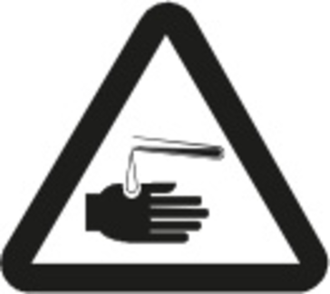 | Risk of acid burns! |
 | First aid! |
 | Warning note! |
 | Disposal! |
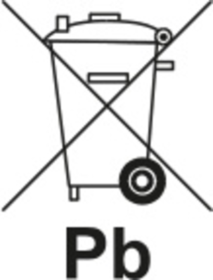 | Do not throw batteries in the bin! |
Risk of explosion!
Do not place tools or similar items on the battery. Short-circuit and risk of explosion.Risk of poisoning!
Never bring wounds into contact with lead. Always clean your hands after working on batteries.Risk of acid burns!
Wear acid-resistant safety goggles, gloves and apronRisk of injury!
Observe the safety regulations when handling batteries and the instruction manual of the charger manufacturer.Only charge the battery using a suitable charger.Disconnect the battery.
Connect the plus cable of the charger to the plus terminal of the battery.
Connect the minus cable of the charger to the minus terminal of the battery.
Insert the mains plug and switch on the charger.
Charge the battery with the lowest possible charging current.
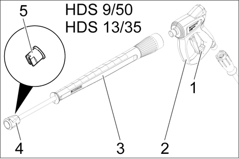
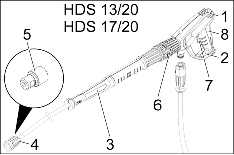
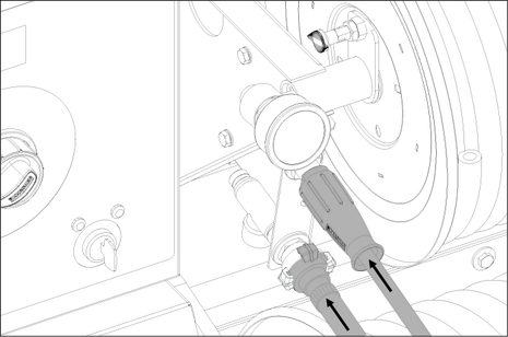
Connect the spray lance to the trigger gun.
Tighten the screw connection of the spray lance fingertight.
Place the high-pressure nozzle into the union nut.
Fit the union nut and hand-tighten.
Connect the high-pressure hose to the high-pressure gun.
Risk of damage!
High-pressure hose is pressurised.
Always unroll the high-pressure hose completely.HDS 13/20, HDS 17/20 only:
The EASY!Lock system connects components quickly and safely via a single turn of the quick-release thread.
See the "Technical data" for the connected loads.
Unroll the water hose from the hose reel and connect it to the water inlet (e.g. tap).
Open the supply tap of the water reservoirs.
Unroll the water hose from the hose reel and connect it to the water inlet (e.g. tap).
Open water inlet.
The water reservoirs are filled via the float container. When the water reservoirs are filled, the float valve in the float container closes.
Close the water inlet.
Disconnect the water hose from the water inlet.
Roll the water hose onto the hose reel.
Flammable fluids
Risk of explosion
Do not spray inflammable liquids.Operation without spray lance
Risk of injury
Never operate the device without the spray lance installed.Before each use, check that the spray lance is firmly seated. The screw connection of the spray lance must be tightened hand tight.High-pressure water jet
Danger of injury
Never fasten the trigger and safety lever in the actuated position.Do not use the high-pressure gun when the safety lever is damaged.Push the safety latch of the high-pressure gun forwards every time before starting work with the device.Hold the high-pressure gun and spray lance with both hands.Operation with an empty fuel tank
Destruction of the fuel pump
Never operate the device with an empty fuel tank.Opening the high-pressure gun: Actuate the safety lever and trigger.
Closing the high-pressure gun: Release the safety lever and trigger.
Risk of injury!
The high-pressure gun is pressurised.
Turn off the device before changing the nozzle and operate the high-pressure gun until the device is depressurised.Switch off the device and operate the high-pressure gun until the device is depressurised.
Secure the high-pressure gun by pushing the safety latch forwards.
Change the nozzle.
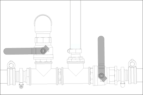
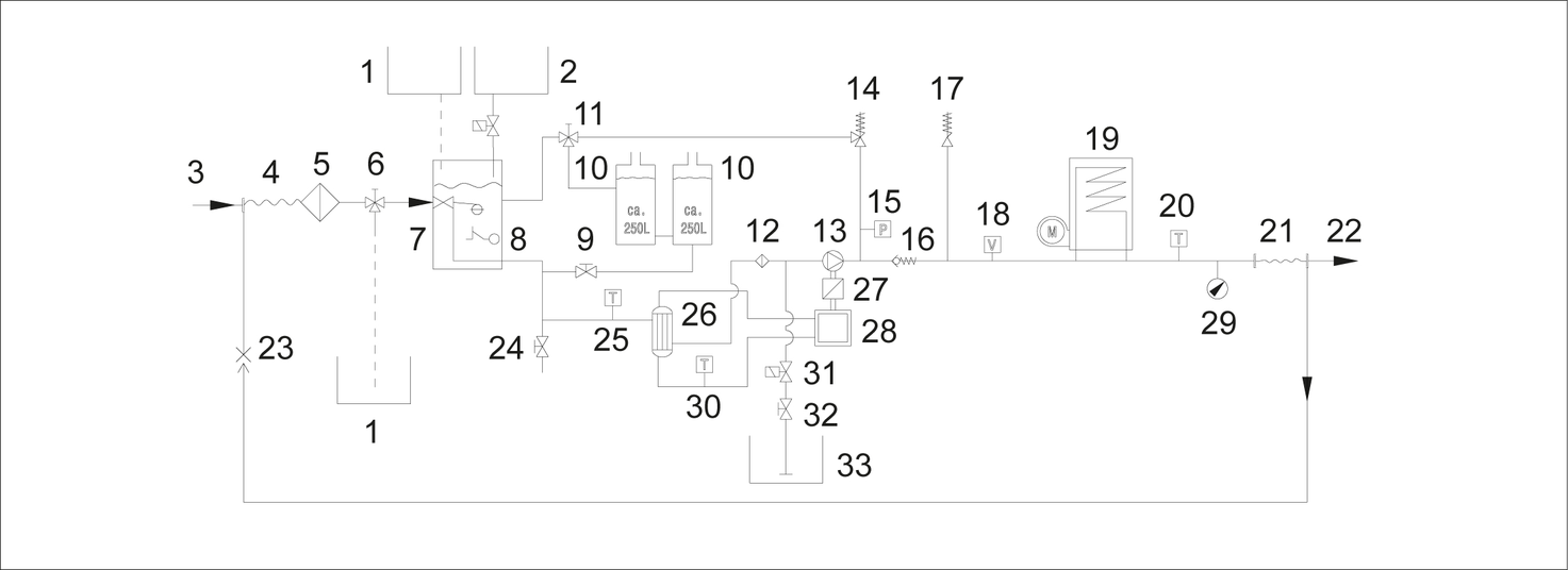
The water supply can either take place via an external water supply or via the internal water reservoirs (2x250 litres).
Position parallel to travel direction: The return water from the high-pressure pump flows into the float tank when the overflow valve is open.
If the trigger gun is closed in this ball tap position, the device may switch off after a few minutes due to too high temperature (see Troubleshooting/ERROR 3).
Position lateral to travel direction: The return water of the high-pressure pump flows into the water reservoirs when the overflow valve is open.
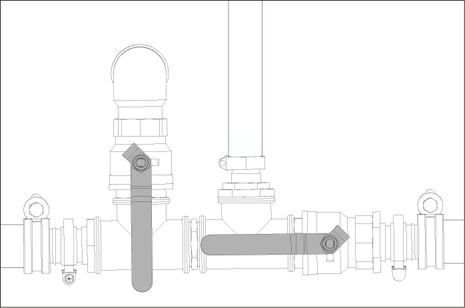
Place the actuation lever of the return flow valve ball tap parallel to the travel direction (20L).
Close the supply tap of the water reservoir.
Set the actuation lever of the return flow valve ball tap lateral to the travel direction (500L).
Open the supply tap of the water reservoirs.
The device can only be operated when the front cover is closed. If the front cover is opened, the device shuts down and the indicator light is on.
Due to the bleeding procedure, the speed of the motor may vary until the final operating pressure has been reached.
Unlock the emergency-stop switch by pulling.
Open rear cover
Establish the water supply.
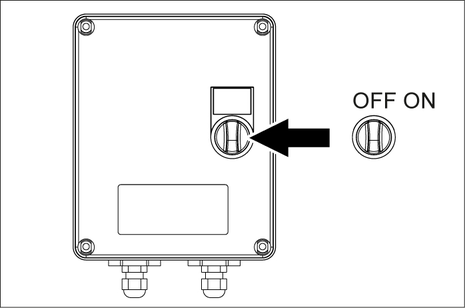
Insert the key into the key switch.
With cold motor only: To preheat the motor, turn the key switch to the left and hold it until the indicator light for preheating goes out.
Turn key switch to position "I".
The standby mode indicator light lights up. The control voltage is switch on and the display shows the operating state.
Turn the key switch to the right until the motor is running.
Set the power switch to operation with cold/hot water.
Unlock the high-pressure gun by pushing the safety latch backwards.
Open the high-pressure gun.
Set the power switch to "0/OFF“ (burner off).
Hot water
Risk of scalding
Avoid contact with hot water.Set the power switch to the desired work temperature (max. 100 °C). The burner is switches on.
HDS 9/50, HDS 13/35 only (optional with HDS 13/20, HDS 17/20):
If the motor speed is increased, the operating pressure also rises. This can be read from the pressure gauge.
Increasing the speed:
Push up the lever of the speed control.
Reducing the speed:
Push down the lever of the speed control.
HDS 13/20, HDS 17/20 only:
Adjust the working pressure and flow rate by turning the pressure/quantity control at the high-pressure gun (+/-).
Risk of injury!
Take care to ensure that the spray lance screw connection does not release when adjusting the pressure/quantity control.HDS 13/20, HDS 17/20 only:
Damage from unsuitable detergents
Unsuitable detergents may damage the device and the object to be cleaned.
Only use the detergent intended for the object.Use detergents sparingly to conserve the environment.
Observe the recommended dosage and instructions provided with the detergents.
Only detergents that have been approved by the device manufacturer may be used.
Kärcher detergents ensure fault-free operation. Ask us for a consultation, request our catalogue or our detergent information sheets.
Place the detergent suction hose in a container filled with detergent and tighten the screw cap.
Set the detergent dosing valve to the desired concentration.
To prevent detergent from flowing back into the float tank or water reservoirs when operating with detergent and a closed trigger gun, the detergent dosing valve must be closed.
HDS 13/20, HDS 17/20 only (option):
The speed control attachment kit (option, ex works: 2.013-086.7, retrofit kit: 2.013-014.0) is absolutely essential for operating the weed removal system! Operation in accordance with the operating instructions for weed removal WR 10, part no. 5.968-256.0 or WR 20/WR 50/WR 100, part no. 5.967-455.0!
The following information must also be observed:
Install WR 10, 20, 50 or 100 onto the spray lance and insert the appropriate nozzle (see corresponding operating instructions).
Turn key switch to position "I".
The standby mode indicator light lights up. The control voltage is switch on and the display shows the operating state.
Push the lever of the speed control down as far possible.
Set the power switch to the "Weed removal V2.0" operating mode.
Turn the key switch to the right until the motor is running.
Unlock the high-pressure gun by pushing the safety latch backwards.
Open the high-pressure gun.
TEMP LOW appears on display: It takes about 2 - 4 minutes before the work temperature has been reached.
TEMP OKAY appears on display:
Perform weed removal.
Set the power switch to the "Weed removal V3.0 & V5.0" operating mode.
Switch on the WR box, set the switch to "ON".
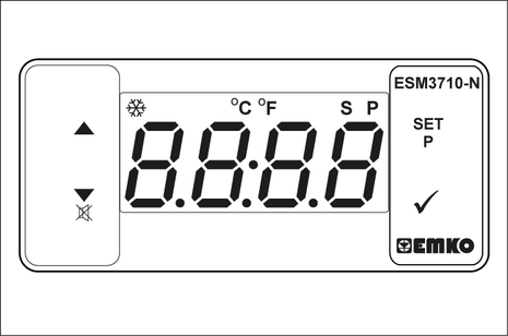
Adjust the temperature using SET and the ˄˅ buttons. Confirm with √ (setting range, 85-105 °C).
Turn the key switch to the right until the motor is running.
Unlock the high-pressure gun by pushing the safety latch backwards.
Open the high-pressure gun.
It takes about 2 - 4 minutes before the work temperature has been reached.
Perform weed removal.
HDS 13/20, HDS 17/20 only (option):
The speed control attachment kit (option, ex works: 2.013-086.7, retrofit kit: 2.013-014.0) is absolutely essential for operation in steam mode!
Risk of scalding!
Increased working pressure due to high work temperature.
Keep in mind that at work temperatures above 105 °C, the working pressure must not exceed 3.2 MPa (32 bar).Operation with 2 spray lances is not possible for steam cleaning.
Steam cleaning: Fit the appropriate steam nozzle to the spray lance (see technical data for part no.).
Disinfection: Mount WR 10, 20, 50, or 100 on the spray lance and insert the appropriate steam nozzle (see Technical Data for part number).
Set the power switch to the "steam mode" operating mode.
Switch on the WR box, set the switch to "ON".
Adjust the temperature using SET and the ˄˅ buttons. Confirm with √ (recommended setting range, 120-155 °C).
Turn the key switch to the right until the motor is running.
Open the bonnet and turn the handwheel on the overflow valve anti-clockwise according to the pressure gauge to 30 bar.
Unlock the high-pressure gun by pushing the safety latch backwards.
Open the high-pressure gun.
It takes about 2 - 4 minutes before the work temperature has been reached.
Carry out steam cleaning or disinfection.
Safety functions
WR-Box indicator light lights up red System pressure too high, burner switches off, see Help with faults.
ERROR 5 appears on the display on the control panel: System pressure too low, the burner does not start, see Help with faults/ERROR 5.
Close the high-pressure gun.
Lock the high-pressure gun by pushing the safety latch of the high-pressure gun to the front.
When the high-pressure gun is closed, the motor continues to run at idling speed. This way the water circulates between the float container and the high-pressure pump and heats up. If the maximum admissible temperature (55 °C) is reached, the motor is switched off by the temperature sensor at the water inlet. After it has cooled down to below 50 °C, the device can be put in operation again.
HDS 13/20, HDS 17/20 only:
Set the detergent dosing valve to "0".
Flush the device clean for at least 1 minute with the high-pressure gun open.
Risk of injury from hot water or steam
Risk of scalding
After operation with hot water or steam, the device must be operated with the gun opened with cold water for at least two minutes to cool it down.Risk of damage!
Risk of damageNever switch off the motor under full load with the trigger gun open.Set the power switch to "0/OFF“ (burner off).
Close the trigger gun.
Motor regulates to idle speed.
Turn key switch to position "0".
The Standby mode indicator light goes out. The control voltage is switched off and the display goes out.
With external water supply: Close the water inlet.
Actuate the high-pressure gun until the device is depressurised.
Secure the high-pressure gun with the safety latch against unintentional opening.
With external water supply: Disconnect the water hose from the water inlet and coil up the water hose onto the hose reel.
Coil the high-pressure hose onto the hose reel.
To protect from freeze damage, the device must be flushed with antifreeze.
Use normal glycol-based anti-freezing agents for automobiles.
Observe the handling instructions of the anti-freeze manufacturer.
This also provides a certain degree of corrosion protection.
Check the coolant circuit of the motor for sufficient antifreeze, refill antifreeze as needed.
See Maintenance Procedures "Check and refill the coolant“.
If the device is not used for an extended period and if there is frost, remove the battery and store it in a location protected from frost.
With external water supply: Disconnect the water hose from the water inlet.
Set the power switch to "0/OFF“ (burner off).
Depressurise the device.
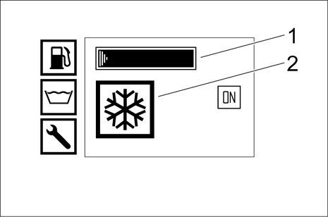
Set the power switch to the operating mode "frost protection".
HDS 13/20, HDS 17/20 only: Set dosing valve for detergent to maximum. Pull the detergent suction hose out of the detergent container and place it in such a way that it can be sucked empty.
Open the supply tap of the water reservoirs and the drain tap in order to completely drain the device.
The filling level indicator of the water reservoirs dips completely.
Close the supply tap of the water reservoirs and the drain tap.
Disconnect the high-pressure gun from the high-pressure hose.
Connect the high-pressure hose to the frost protection inlet.
Connect the water hose to the return flow of the frost protection.
Prepare the antifreeze in the antifreeze container. Select the mixing ratio of the water/antifreeze as per the instructions of the antifreeze manufacturer.
Check the antifreeze concentration with a commercially available antifreeze tester and adapt if necessary.
Open the filling hole of the float container. In order to do so, loosen the wing screw and push the cover to the left.
Fill 20 litres of antifreeze into the float container and close the filling hole.
Align the actuation lever of the ball tap for antifreeze vertically.
Place the actuation lever of the return flow valve ball tap parallel to the travel direction (20L).
With cold motor only: To preheat the motor, turn the key switch to the left and hold it until the indicator light for preheating goes out.
Turn key switch to position "I".
The standby mode indicator light lights up. The control voltage is switch on and the display shows the operating status "Antifreeze".
Turn the key switch to the right until the motor is running.
The antifreeze liquid is pumped through the device in a circuit.
Lead the residual water via the frost protection hose into the anti-freeze container.
As soon as antifreeze exits the antifreeze hose, put the operating lever of the frost protection ball tap in the horizontal position and wait for 5 seconds.
Switch off the engine.
Set the power switch to "0/OFF“ (burner off).
Prior to operation, the antifreeze must be pumped from the high-pressure system back into the antifreeze container
Align the actuation lever of the ball tap for antifreeze vertically.
Connect the high-pressure hose to the frost protection inlet.
Connect the water hose to the return flow of the frost protection.
Open the filling hole of the float container. In order to do so, loosen the wing screw and push the cover to the left.
Fill 20 litres of fresh water into the float container and close the filling hole.
Set the power switch to the operating mode "frost protection".
With cold motor only:
To preheat the motor, turn the key switch to the left and hold it until the indicator light for preheating goes out.Turn key switch to position "I". The standby mode indicator light lights up. The control voltage is switch on and the display shows the operating status "Antifreeze".
Turn the key switch to the right until the motor is running.
The antifreeze fluid is forwarded from the float container into the antifreeze container with fresh water.Rinse for approx. 2 minutes until the antifreeze container is filled.
Switch off the engine.
Set the power switch to "0/OFF“ (burner off).
Risk of injury and damage!
Improper transportation
Mind the weight of the device during transport.Risk of damage!
Improper transportation
Protect the trigger from damage during transport.Note: The driver driving the towing vehicle on public roads must ensure that he/she has the appropriate license for this (driving license class).
Unpredictable driving behaviour
With a partially filled water reservoir, the device can rock up or tip over under extreme steering movements or braking situations.
Drain or fill the water reservoir before driving.With a permissible total weight of 1600 kg, fill or empty the water reservoir completely.
With a permissible total weight of 1100 kg, empty the water reservoir completely.On devices without a hose reel, unscrew the high-pressure hose from the high-pressure outlet and stow it in the device.
Pivot the front bar (option) forwards and lock in place.
Pull the rear tarpaulin (option) down an lock in place.
Use the support wheel to adjust the tow bar to the height of the towing hitch on the towing vehicle.
Attach the tear-off rope to the towing vehicle.
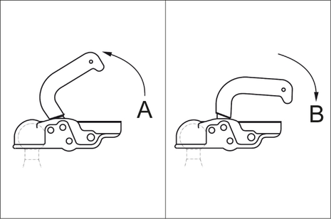
Pull the coupling lever up (open).
Fit the tow bar onto the towing hitch ball.
Press the coupling lever down (close) until it lies parallel to the tow bar.
Plug in the socket plug connection for the vehicle lighting.
Rotate the support wheel up by means of the crank.
Ensure that the support wheel points toward the trailer when fully retracted.
Remove the chocks from the wheels and insert them into the holders.
Release the parking brake.
Check that the trailer lighting system (brake lights, indicator lights, tail lights, license plate light) is functioning correctly.
Check the running surfaces of the tyres for embedded objects.
Check the condition of the tyres.
Check the tyre pressure, see "Maintenance work".
Note: Note the locally applicable speed limits for vehicles with trailers and adhere to these.
Improper crane transport
Risk of injury from a falling device or falling objects
Observe the local regulations for accident prevention and the safety instructions.The device may only be transported with a crane by persons instructed in the operation of the crane.Check the lifting gear for damage before each crane transport.Check the handle for damage before each crane transport.Lift the device only by the handle.Do not use an slinging chains.Secure the lifting gear against unintentional unhooking of the load.Remove the spray lance with high-pressure gun, nozzles, surface cleaner and other loose objects before transporting by crane.Do not transport any objects on the device during the lifting operation.Do not stand under the suspended load.Ensure that no persons are in the hazard zones of the crane.Do not leave the device handing unattended on the crane.Risk of injury or damage due to non-observance of the weight!
When transporting and storing the device, there is a risk of injury and damage due to its weight.
Take into account the weight of the device for transportation and storage, see chapter Technical data.Risk of damage due to frost!
Water that is not completely drained can damage the device and accessories during freezing.
Empty the water completely from the device and accessories.Protect the device and accessories from frost.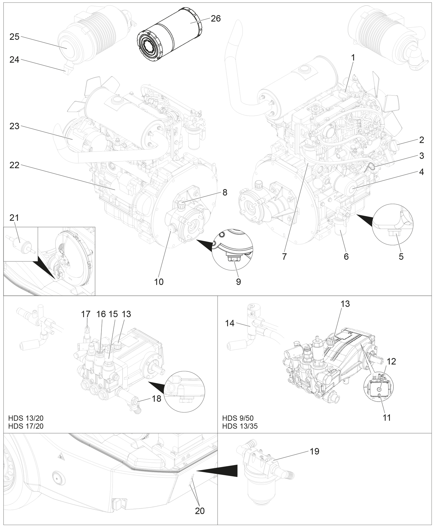
Symbol | Type of Customer Service |
|---|---|
 | Burner service |
 | Motor service |
 | Pump service |
 | High-pressure gun service |
Time & date | Activity | By whom |
|---|---|---|
Before each journey | Check lighting. | Operator |
Check the tyre pressure and condition of the tyres. | Operator | |
Daily | Check the condition of the oil in the high-pressure pump sight glass. Do not start up the device if the oil is milky. Notify Customer Service. ATTENTIONRisk of damage! In case of lacteous oil, inform Kärcher customer service immediately | Operator |
General visual inspection of the device. | Operator | |
Check the high-pressure hose for damage. Do not continue using damage high-pressure hoses. | Operator | |
Check the water inlet filter, clean if necessary | Operator | |
Check the pump prefilter, clean if necessary. | Operator | |
Check oil level on the motor, refill oil if necessary. | Operator | |
Check oil level at the intermediate gearbox, refill oil if necessary. | Operator | |
Check the fuel filter on the motor, inform customer service if necessary. | Operator | |
Check the water separator on the motor, inform customer service if necessary. | Operator | |
Check coolant level in the equalisation container, refill coolant if needed. | Operator | |
Check fuel filter, contact customer service if necessary. | Operator | |
Check the filter on the detergent suction hose, clean if necessary. | Operator | |
Check line system for leaks. | Operator | |
Once after the first 50 operating hours | Check the V-belt tension at the fan, retension if necessary. | Operator |
Replace oil in the motor. | Customer Service department | |
Change the oil in the high pressure pump. | Customer Service department | |
Every 50 operating hours or 3 months | Check the battery. | Customer Service department |
Every 200 operating hours | Check the air filter or air filter inlay, clean if necessary. | Operator |
Check the V-belt tension at the fan, retension if necessary. | Operator | |
Check the intermediate gearbox for leaks. | Customer Service department | |
Clean the sieve on the filling nozzle of the fuel tank. | Customer Service department | |
Replace oil in the motor. | Customer Service department | |
Replace oil filter inlay on motor. | Customer Service department | |
Perform maintenance tasks in accordance with the maintenance plan. | Customer Service department | |
Every 400 operating hours or annually | Replace the air filter insert. | Operator |
Check fuel filter, replace if necessary. | Customer Service department | |
Perform maintenance tasks in accordance with the maintenance plan. | Customer Service department | |
Every 600 operating hours or annually | Change the oil in the high pressure pump. | Customer Service department |
Every 800 operating hours. | Check the blower motor for proper function, replace sliding contacts (carbon brushes) if necessary. | Operator |
Every 1000 operating hours or annually. | Replace coolant. | Customer Service department |
Every 1000 operating hours. | Replace oil in the intermediate gearbox. | Customer Service department |
Replace V-belt on the ventilator. | Customer Service department | |
Check the valve clearance at the cylinder head of the motor, adjust if necessary. | authorized Yanmar dealer | |
Every 1600 operating hours. | Check injectors on the motor, clean if necessary. | authorized Yanmar dealer |
Check the crankshaft casing ventilation on the motor, clean if necessary. | authorized Yanmar dealer | |
Every 2000 operating hours or every 2 years | Replace fuel hoses on the motor. | authorized Yanmar dealer |
Replace cooling system hoses on the motor. | authorized Yanmar dealer | |
Every 2000 operating hours | Check the valves and valve seats on the cylinder head of the motor, lap if necessary. | authorized Yanmar dealer |
Only applies to devices with vapour mode attachment kit: | ||
Recurring every 5 years at the latest | Perform the pressure test according to the manufacturer's specifications. | Customer Service department |
Turn the key-operated switch to off and remove the key before performing any work on the device.
Risk of injury from electric shock
Do not place metallic objects on the alternator or the starter.
Risk of explosion!
Risk of injury and damage
Do not place any tools or objects on the battery, i.e. on the end poles and cell connectors.Naked flames and smoking must be strictly avoided.Ensure the room is well ventilated when charging batteries.Only use batteries and chargers approved by Kärcher (original spare parts).Allow the device to cool down.
Disassemble the water inlet filter and take out the filter inlay.
Clean the filter with clean water or compressed air.
Assemble in the reverse order.
Depressurise the device.
Disassemble the pump prefilter and take out the filter inlay.
Clean the filter with clean water or compressed air.
Assemble in the reverse order.
Unscrew the screw cap of the detergent suction hose.
Take out detergent suck hose.
Clean filter in water and reinstall.
The filling quantity between the MIN and MAX markings on the oil dipstick is 1.6 litres.
Remove the oil dipstick, wipe it and reinsert it.
Remove the oil dipstick one more time and check the oil level.
The oil level is correct if it is within the markings on the oil dipstick.
If the oil level is below the mark, open the filling hole lid and add fresh motor oil.
Wait five minutes, until the oil has collected in the oil pan.
Check the oil level as described above.
Repeat this procedure as often as necessary until the oil level is between the markings on the oil dipstick.
After the check, insert the oil dipstick and close the lid of the filling hole.
The air bubbles must be able to escape.
For oil type refer to technical specifications
Check the oil level at the oil-level gauge of the intermediate gearbox.
The oil level is correct if it is in the middle of the oil-level gauge.
If the oil level is below the middle of the oil-level gauge, open the lid of the filling hole and fill in fresh transmission oil.
Close filling hole.
The air bubbles must be able to escape.
For oil type refer to technical specifications
Remove the oil dipstick, wipe it and insert it again.
Remove the oil dipstick again and check the oil level.
The oil level is correct if it is within the markings on the oil dipstick.If the oil level is below the mark on the oil dipstick, fill up with fresh oil.
Twist in the oil dipstick.
Air bubbles must be able to escape.
For oil type refer to technical specifications
Harmful substances can be produced.
Observe the brand of antifreeze used.The mixture can cause a chemical reaction.Do not mix different types of antifreeze.Risk of motor overheating
A lack of coolant can cause the motor to overheat.
Switch off the motor immediately and allow it to cool down.Risk of motor overheating
A lack of coolant can cause the motor to overheat.
If the motor overheats to the point where steam escapes, turn off the motor and maintain a safe distance until the pressure has decreased.Danger of scalding from motor coolant
The expansion tank is pressurised.
Never open the lid on the expansion tank of the motor coolant at operating temperature.Open the lid on the expansion tank of the motor coolant, fill in fresh clean water and the required antifreeze.
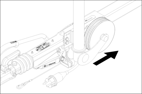
For a coarse cleaning of the air filter, hold the catch pan under the dirt outlet and operate the dirt outlet.
Heavily soiled or defective filter inlays must always be replaced.
Loosen the spring tension bracket, remove the cover and eliminate the dust deposits.
Take out the filter inlay.
Blow out the filter inlay with compressed air (max. 2 bar) from the inside.
Clean the inside of the air filter housing with a cloth.
Insert the filter inlay into the air filter casing.
Attach the cover and fasten it by means of the spring tension bracket.
If the V-belt is not sufficiently tensioned, this can cause overheating of the motor or insufficient battery charge.
Shut off the motor and remove the key from the key switch.
Press the belt with your thumb to check the V-belt tension.
You should be able to push the V-belt in by approx. 7-9 mm.
The defective V-belts must be replaced immediately.
Use a commonly available grease gun to inject the appropriate grease into both grease nipples.
Place the device on a level surface.
Connect the tyre pressure gauge device to the tyre valve.
Check the type pressure (see "Technical data") and correct if necessary.
Risk of fatal injury from moving traffic
Park the device on a level surface and wear high-visibility clothing when carrying out repair work on public roads.
Park the device on a level surface.
Check that the ground is stable. Additionally secure the device against rolling away with a wheel chock.
Lock parking brake.
Check the tyres.
Check the tyre running surfaces for embedded objects.
Remove objects found.
Use suitable, commercially available materials to carry out tyre repairs.
Observe the manufacturer's recommendations. The journey may be resumed providing that the directions supplied by the product manufacturer have been observed. The tyre/wheel change should nonetheless be carried out as soon as possible.
Place the jack at the relevant position point.
Loosen the wheel screws.
Lift the device with a jack.
Unscrew the wheel bolts.
Remove the wheel.
Mount spare wheel.
Apply the wheel bolts.
Lower the device with the jack.
Tighten the wheel screws crosswise.
Tightening torque | 110-120 Nm |
No jack included in the scope of delivery.
Use a suitable, commonly available jack.
Have the brake system and the Chassis and Suspension checked regularly by an authorised dealer workshop.
Inadvertently starting up device
Risk of injury, electric shock
Turn the key-operated switch to "0" and remove the key before performing any work on the device.Inadvertently starting up device, touching live components
Risk of injury, electric shock
Switch off the device before performing any work on the device.Remove the mains plug.Risk of explosion and short-circuit. Do not place any tools or similar on the battery.
Allow the device to cool down.
ERROR 10* Burner temperature Cleaning operation with cold water is possible.
ERROR 11* Flame sensor (no flame) Cleaning operation with cold water is possible.
ERROR 12* Flame sensor (flame does not go out) Cleaning operation with cold water is possible.
HDS 13/20, HDS 17/20 only:Insufficient or no detergent delivery
Overflow valve keeps switching on/off when the trigger gun is opened
ERROR 1
Charging current
Cause:
V-belt tension on the fan too low.
Remedy:
Operator
Retension the V-belt on the fan.
Cause:
Alternator defective.
Remedy:
Customer Service department
Check alternator, replace if necessary.
Cause:
Charging current monitoring defective.
Remedy:
Customer Service department
Check wiring + relay K9.
ERROR 3
Temperature of water inlet or cooling water
Cause:
Water temperature in the float container too high due to circulation mode.
Remedy:
Operator
Allow the water to cool down or drain it. Set the actuation lever of the return flow valve ball tap lateral to the travel direction (500L).
Cause:
Temperature sensor of water inlet has switched off the device
Remedy:
Operator
Turn the device off and back on. If the malfunction occurs repeatedly, notify customer service.
Cause:
Temperature sensor of water inlet defective.
Remedy:
Customer Service department
Replace the temperature sensor.
Cause:
Coolant level too low.
Remedy:
Operator
Fill coolant into the expansion tank.
Cause:
V-belt tension on the fan too low.
Remedy:
Operator
Retension the V-belt on the fan.
Cause:
Temperature sensor for cooling water on the motor defective.
Remedy:
Customer Service department
Replace the temperature sensor.
ERROR 4
Water shortage
Cause:
External water supply: Water inlet pressure too low.
Remedy:
Operator
Check the water inlet.
Cause:
Internal water supply: Water reservoirs empty.
Remedy:
Operator
Fill water reservoirs.
Cause:
Water shortage safeguard in the float container defective.
Remedy:
Customer Service department
Replace the water shortage safeguard.
Cause:
Water inlet filter dirty.
Remedy:
Operator
Clean the water inlet filter.
Cause:
Water hose leaky or kinked.
Remedy:
Customer Service department
Replace water hose.
Cause:
Float valve in the float container is soiled.
Remedy:
Customer Service department
Clean float valve.
Cause:
Float valve in the float container jammed or defective.
Remedy:
Customer Service department
Clean or replace the float valve.
ERROR 5
Flow switch / pressure switch
Cause:
Flow switch defective.
Remedy:
Customer Service department
Replace flow switch.
Cause:
Pressure switch faulty.
Remedy:
Customer Service department
Replace the pressure switch.
Cause:
Overflow valve is defective.
Remedy:
Customer Service department
Replace overflow valve.
Cause:
Check valve in the overflow valve defective.
Remedy:
Customer Service department
Replace the check valve.
Cause:
Pump prefilter dirty.
Remedy:
Operator
Clean the pump prefilter.
Cause:
Steam mode: System pressure too low
Remedy:
Operator
Raise the system pressure in small increments by turning the handwheel on the overflow valve clockwise.
ERROR 6
Fuel sensor
Cause:
Fuel tank empty.
Remedy:
Operator
Refuel.
Cause:
Float of the fuel sensor jammed.
Remedy:
Customer Service department
Check the float.
Cause:
Fuel sensor defective.
Remedy:
Customer Service department
Replace fuel sensor.
ERROR 9*
Emission temperature
Cause:
Exhaust gas thermostat has responded and switched off the burner.
Remedy:
Operator
Switch off the device, allow to cool down and restart. If the malfunction occurs repeatedly, notify customer service.
Cause:
Exhaust gas thermostat defective.
Remedy:
Customer Service department
Replace the exhaust gas thermostat.
Cause:
Burner has been wrongly set.
Remedy:
Customer Service department
Adjust the burner.
Cause:
Heating coil soiled or calcified.
Remedy:
Customer Service department
Decarbonise or descale heating coil.
ERROR 10*
Burner temperature
Cleaning operation with cold water is possible.
Cause:
Temperature sensor for burner (NTC) has switched off the burner.
Remedy:
Operator
Turn the device off and back on. If the malfunction occurs repeatedly, notify customer service.
Cause:
Temperature sensor of the burner is defective.
Remedy:
Customer Service department
Replace the temperature sensor.
ERROR 11*
Flame sensor (no flame)
Cleaning operation with cold water is possible.
Cause:
Nozzle holder soiled.
Remedy:
Customer Service department
Clean the nozzle holder.
Cause:
Ignition electrodes have been set up wrongly or are dirty.
Remedy:
Customer Service department
Properly adjust or clean the ignition electrodes.
Cause:
Photo cell of the flame monitoring defective.
Remedy:
Customer Service department
Replace the photo cell.
Cause:
Fuel pump defective.
Remedy:
Customer Service department
Replace fuel pump.
Cause:
Solenoid valve fuel is defective.
Remedy:
Customer Service department
Replace the solenoid valve.
Cause:
Fuel filter choked.
Remedy:
Customer Service department
Replace fuel filter.
Cause:
Ignition transformer defective.
Remedy:
Customer Service department
Replace the ignition transformer.
ERROR 12*
Flame sensor (flame does not go out)
Cleaning operation with cold water is possible.
Cause:
Photo cell of the flame monitoring defective.
Remedy:
Customer Service department
Replace the photo cell.
Cause:
Burner sooted, "afterglow".
Remedy:
Customer Service department
Have the burner decarbonised.
ERROR 14
Switch-off after 45 minutes continuous break
Cause:
Standby time of 45 minutes exceeded.
Remedy:
Operator
Turn the device off and back on.
ERROR 15
Switch-off after 45 minutes continuous operation
Cause:
Continuous operation exceeds 45 minutes.
Remedy:
Operator
Turn the device off and back on.
Device stops, display switches off
Cause:
Blown fuse.
Remedy:
Operator
Replace fuse.
Cause:
No power supply to inverter because of battery undervoltage or overvoltage.
Remedy:
Operator
Check battery, charge if necessary.
Cause:
Inverter defective.
Remedy:
Customer Service department
Replace inverter.
No display after switching the device on
Cause:
Battery depleted.
Remedy:
Operator
Charge the battery.
Cause:
Blown fuse.
Remedy:
Operator
Replace fuse.
Cause:
Front cover open.
Remedy:
Operator
Close front cover.
Cause:
Emergency stop switch depressed.
Remedy:
Operator
Unlock the emergency-stop switch by pulling.
Cause:
No power supply to inverter because of battery undervoltage or overvoltage.
Remedy:
Operator
Check battery, charge if necessary.
Cause:
Inverter defective.
Remedy:
Customer Service department
Replace inverter.
Engine does not start or stops again immediately
Cause:
Notify Customer Service.
Working pressure fluctuates
Cause:
Leak in the suction section of the high-pressure pump.
Remedy:
Customer Service department
Check line system.
Cause:
Valves worn.
Remedy:
Customer Service department
Replace valves.
Burner emitting sooty smoke
Cause:
Burner incorrectly adjusted or soiled.
Remedy:
Customer Service department
Adjust or clean burner.
Cause:
Solenoid valve fuel defective, diesel fuel is dripping.
Remedy:
Customer Service department
Check the solenoid valve; replace solenoid or solenoid valve if necessary.
White smoke from burner
Cause:
No ignition spark (can be detected through the sight glass in the burner lid).
Remedy:
Operator
Notify Customer Service.
Cause:
Condensation in the nozzle holder.
Remedy:
Customer Service department
Check, clean the nozzle holder.
Cause:
Fuel pressure too low.
Remedy:
Customer Service department
Check the fuel pump.
Indicator light front cover/emergency stop is on
Cause:
The front cover was opened during the operation.
Remedy:
Operator
Close front cover.
Cause:
Safety button of front cover is defective.
Remedy:
Customer Service department
Check safety button.
Cause:
Emergency stop switch depressed.
Remedy:
Operator)
Unlock the emergency-stop switch by pulling.
Water leaks from the bottom of the device.
Cause:
High-pressure pump is leaky.
Remedy:
Customer Service department
Device not building up pressure
Cause:
Nozzle is blocked/ washed out.
Remedy:
Customer Service department
Clean/replace the nozzles.
Cause:
Motor operating speed too low.
Remedy:
Customer Service department
Check the operating speed of the motor.
Cause:
HDS 9/50, HDS 13/35 only (optional with HDS 13/20, HDS 17/20): Speed control defective.
Remedy:
Customer Service department
Check speed control.
Cause:
Safety valve is leaky.
Remedy:
Customer Service department
Check the setting; install new washers, if required.
Cause:
Supply lines to the pump are leaky or clogged.
Remedy:
Customer Service department
Check all supply lines to the pump.
High-pressure pump knocking
Cause:
Supply lines to the pump are leaky.
Remedy:
Customer Service department
HDS 13/20, HDS 17/20 only:Insufficient or no detergent delivery
Cause:
Detergent dosing valve is closed or leaking/clogged
Remedy:
Operator
Open or check/clean detergent dosing valve.
Cause:
Detergent suction hose with filter leaking or blocked
Remedy:
Operator
Check/clean detergent suction hose with filter.
Cause:
Detergent solenoid valve leaky or clogged.
Remedy:
Customer Service department
Check, clean detergent solenoid valve.
Cause:
Electronics or detergent solenoid valve is defective.
Remedy:
Customer Service department
Replace electronics or detergent solenoid valve.
Overflow valve keeps switching on/off when the trigger gun is opened
Cause:
Nozzle is clogged.
Remedy:
Operator
Clean the nozzles.
Cause:
Device is scaled.
Remedy:
Customer Service department
Descale the device.
Cause:
Overflow valve is defective.
Remedy:
Customer Service department
Replace overflow valve.
Cause:
The switching point of the overflow valve has become misaligned
Remedy:
Customer Service department
Adjust the overflow valve.
WR-Box indicator light lights up red
Cause:
Steam mode: System pressure too high
Remedy:
Operator
If the malfunction cannot be corrected, the device must be checked by the Customer Service department.
ERROR 10* Burner temperature Cleaning operation with cold water is possible.
ERROR 11* Flame sensor (no flame) Cleaning operation with cold water is possible.
ERROR 12* Flame sensor (flame does not go out) Cleaning operation with cold water is possible.
HDS 13/20, HDS 17/20 only:Insufficient or no detergent delivery
Overflow valve keeps switching on/off when the trigger gun is opened
ERROR 1
Charging current
Cause:
V-belt tension on the fan too low.
Remedy:
Operator
Retension the V-belt on the fan.
Cause:
Alternator defective.
Remedy:
Customer Service department
Check alternator, replace if necessary.
Cause:
Charging current monitoring defective.
Remedy:
Customer Service department
Check wiring + relay K9.
ERROR 3
Temperature of water inlet or cooling water
Cause:
Water temperature in the float container too high due to circulation mode.
Remedy:
Operator
Allow the water to cool down or drain it. Set the actuation lever of the return flow valve ball tap lateral to the travel direction (500L).
Cause:
Temperature sensor of water inlet has switched off the device
Remedy:
Operator
Turn the device off and back on. If the malfunction occurs repeatedly, notify customer service.
Cause:
Temperature sensor of water inlet defective.
Remedy:
Customer Service department
Replace the temperature sensor.
Cause:
Coolant level too low.
Remedy:
Operator
Fill coolant into the expansion tank.
Cause:
V-belt tension on the fan too low.
Remedy:
Operator
Retension the V-belt on the fan.
Cause:
Temperature sensor for cooling water on the motor defective.
Remedy:
Customer Service department
Replace the temperature sensor.
ERROR 4
Water shortage
Cause:
External water supply: Water inlet pressure too low.
Remedy:
Operator
Check the water inlet.
Cause:
Internal water supply: Water reservoirs empty.
Remedy:
Operator
Fill water reservoirs.
Cause:
Water shortage safeguard in the float container defective.
Remedy:
Customer Service department
Replace the water shortage safeguard.
Cause:
Water inlet filter dirty.
Remedy:
Operator
Clean the water inlet filter.
Cause:
Water hose leaky or kinked.
Remedy:
Customer Service department
Replace water hose.
Cause:
Float valve in the float container is soiled.
Remedy:
Customer Service department
Clean float valve.
Cause:
Float valve in the float container jammed or defective.
Remedy:
Customer Service department
Clean or replace the float valve.
ERROR 5
Flow switch / pressure switch
Cause:
Flow switch defective.
Remedy:
Customer Service department
Replace flow switch.
Cause:
Pressure switch faulty.
Remedy:
Customer Service department
Replace the pressure switch.
Cause:
Overflow valve is defective.
Remedy:
Customer Service department
Replace overflow valve.
Cause:
Check valve in the overflow valve defective.
Remedy:
Customer Service department
Replace the check valve.
Cause:
Pump prefilter dirty.
Remedy:
Operator
Clean the pump prefilter.
Cause:
Steam mode: System pressure too low
Remedy:
Operator
Raise the system pressure in small increments by turning the handwheel on the overflow valve clockwise.
ERROR 6
Fuel sensor
Cause:
Fuel tank empty.
Remedy:
Operator
Refuel.
Cause:
Float of the fuel sensor jammed.
Remedy:
Customer Service department
Check the float.
Cause:
Fuel sensor defective.
Remedy:
Customer Service department
Replace fuel sensor.
ERROR 9*
Emission temperature
Cause:
Exhaust gas thermostat has responded and switched off the burner.
Remedy:
Operator
Switch off the device, allow to cool down and restart. If the malfunction occurs repeatedly, notify customer service.
Cause:
Exhaust gas thermostat defective.
Remedy:
Customer Service department
Replace the exhaust gas thermostat.
Cause:
Burner has been wrongly set.
Remedy:
Customer Service department
Adjust the burner.
Cause:
Heating coil soiled or calcified.
Remedy:
Customer Service department
Decarbonise or descale heating coil.
ERROR 10*
Burner temperature
Cleaning operation with cold water is possible.
Cause:
Temperature sensor for burner (NTC) has switched off the burner.
Remedy:
Operator
Turn the device off and back on. If the malfunction occurs repeatedly, notify customer service.
Cause:
Temperature sensor of the burner is defective.
Remedy:
Customer Service department
Replace the temperature sensor.
ERROR 11*
Flame sensor (no flame)
Cleaning operation with cold water is possible.
Cause:
Nozzle holder soiled.
Remedy:
Customer Service department
Clean the nozzle holder.
Cause:
Ignition electrodes have been set up wrongly or are dirty.
Remedy:
Customer Service department
Properly adjust or clean the ignition electrodes.
Cause:
Photo cell of the flame monitoring defective.
Remedy:
Customer Service department
Replace the photo cell.
Cause:
Fuel pump defective.
Remedy:
Customer Service department
Replace fuel pump.
Cause:
Solenoid valve fuel is defective.
Remedy:
Customer Service department
Replace the solenoid valve.
Cause:
Fuel filter choked.
Remedy:
Customer Service department
Replace fuel filter.
Cause:
Ignition transformer defective.
Remedy:
Customer Service department
Replace the ignition transformer.
ERROR 12*
Flame sensor (flame does not go out)
Cleaning operation with cold water is possible.
Cause:
Photo cell of the flame monitoring defective.
Remedy:
Customer Service department
Replace the photo cell.
Cause:
Burner sooted, "afterglow".
Remedy:
Customer Service department
Have the burner decarbonised.
ERROR 14
Switch-off after 45 minutes continuous break
Cause:
Standby time of 45 minutes exceeded.
Remedy:
Operator
Turn the device off and back on.
ERROR 15
Switch-off after 45 minutes continuous operation
Cause:
Continuous operation exceeds 45 minutes.
Remedy:
Operator
Turn the device off and back on.
Device stops, display switches off
Cause:
Blown fuse.
Remedy:
Operator
Replace fuse.
Cause:
No power supply to inverter because of battery undervoltage or overvoltage.
Remedy:
Operator
Check battery, charge if necessary.
Cause:
Inverter defective.
Remedy:
Customer Service department
Replace inverter.
No display after switching the device on
Cause:
Battery depleted.
Remedy:
Operator
Charge the battery.
Cause:
Blown fuse.
Remedy:
Operator
Replace fuse.
Cause:
Front cover open.
Remedy:
Operator
Close front cover.
Cause:
Emergency stop switch depressed.
Remedy:
Operator
Unlock the emergency-stop switch by pulling.
Cause:
No power supply to inverter because of battery undervoltage or overvoltage.
Remedy:
Operator
Check battery, charge if necessary.
Cause:
Inverter defective.
Remedy:
Customer Service department
Replace inverter.
Engine does not start or stops again immediately
Cause:
Notify Customer Service.
Working pressure fluctuates
Cause:
Leak in the suction section of the high-pressure pump.
Remedy:
Customer Service department
Check line system.
Cause:
Valves worn.
Remedy:
Customer Service department
Replace valves.
Burner emitting sooty smoke
Cause:
Burner incorrectly adjusted or soiled.
Remedy:
Customer Service department
Adjust or clean burner.
Cause:
Solenoid valve fuel defective, diesel fuel is dripping.
Remedy:
Customer Service department
Check the solenoid valve; replace solenoid or solenoid valve if necessary.
White smoke from burner
Cause:
No ignition spark (can be detected through the sight glass in the burner lid).
Remedy:
Operator
Notify Customer Service.
Cause:
Condensation in the nozzle holder.
Remedy:
Customer Service department
Check, clean the nozzle holder.
Cause:
Fuel pressure too low.
Remedy:
Customer Service department
Check the fuel pump.
Indicator light front cover/emergency stop is on
Cause:
The front cover was opened during the operation.
Remedy:
Operator
Close front cover.
Cause:
Safety button of front cover is defective.
Remedy:
Customer Service department
Check safety button.
Cause:
Emergency stop switch depressed.
Remedy:
Operator)
Unlock the emergency-stop switch by pulling.
Water leaks from the bottom of the device.
Cause:
High-pressure pump is leaky.
Remedy:
Customer Service department
Device not building up pressure
Cause:
Nozzle is blocked/ washed out.
Remedy:
Customer Service department
Clean/replace the nozzles.
Cause:
Motor operating speed too low.
Remedy:
Customer Service department
Check the operating speed of the motor.
Cause:
HDS 9/50, HDS 13/35 only (optional with HDS 13/20, HDS 17/20): Speed control defective.
Remedy:
Customer Service department
Check speed control.
Cause:
Safety valve is leaky.
Remedy:
Customer Service department
Check the setting; install new washers, if required.
Cause:
Supply lines to the pump are leaky or clogged.
Remedy:
Customer Service department
Check all supply lines to the pump.
High-pressure pump knocking
Cause:
Supply lines to the pump are leaky.
Remedy:
Customer Service department
HDS 13/20, HDS 17/20 only:Insufficient or no detergent delivery
Cause:
Detergent dosing valve is closed or leaking/clogged
Remedy:
Operator
Open or check/clean detergent dosing valve.
Cause:
Detergent suction hose with filter leaking or blocked
Remedy:
Operator
Check/clean detergent suction hose with filter.
Cause:
Detergent solenoid valve leaky or clogged.
Remedy:
Customer Service department
Check, clean detergent solenoid valve.
Cause:
Electronics or detergent solenoid valve is defective.
Remedy:
Customer Service department
Replace electronics or detergent solenoid valve.
Overflow valve keeps switching on/off when the trigger gun is opened
Cause:
Nozzle is clogged.
Remedy:
Operator
Clean the nozzles.
Cause:
Device is scaled.
Remedy:
Customer Service department
Descale the device.
Cause:
Overflow valve is defective.
Remedy:
Customer Service department
Replace overflow valve.
Cause:
The switching point of the overflow valve has become misaligned
Remedy:
Customer Service department
Adjust the overflow valve.
WR-Box indicator light lights up red
Cause:
Steam mode: System pressure too high
Remedy:
Operator
The warranty conditions issued by our relevant sales company apply in all countries. We shall remedy possible malfunctions on your appliance within the warranty period free of cost, provided that a material or manufacturing flaw is the cause. In a warranty case, please contact your dealer (with the purchase receipt) or the next authorised customer service site.
Further information can be found at: www.kaercher.com/dealersearch
Further warranty information (if available) can be found in the service area of your local Kärcher website under "Downloads".
If the device is connected to a chimney or if the device cannot be seen, we recommend installing a flame monitor (option).
Only use original accessories and original spare parts. They ensure that the appliance will run safely and fault-free.
Information on accessories and spare parts can be found at www.kaercher.com.
EU Declaration of Conformity |
We hereby declare that the machine described below complies with the relevant basic safety and health requirements in the EU Directives, both in its basic design and construction as well as in the version placed in circulation by us. This declaration is invalidated by any changes made to the machine that are not approved by us.
Product: High-pressure cleaner
Type: 1.524-xxx
Type: 1.999-380.0
Currently applicable EU Directives2006/42/EC (+2009/127/EC)
2000/14/EC
2014/30/EU
2014/68/EU (optional)
Harmonised standards usedEN 60335-1
EN 60335-2-79
EN 1829-1
EN 1829-2
EN ISO 12100
EN 13309: 2010
EN 55012: 2007 + A1: 2009
EN 62233: 2008
Applied conformity evaluation method2000/14/EG: Annex V
Sound power level dB(A)HD 9/23 GeTr1 + HD 9/23 DeTr1
Measured: 105
Guaranteed: 107
HDS 13/20 DeTr1
Measured: 97
Guaranteed: 100
HDS 13/35 DeTr1 + HDS 9/50 DeTr1
Measured: 100
Guaranteed: 102
HDS 17/20 DeTr1
Measured: 100
Guaranteed: 102
OPTIONALProduct: ABS steam HDS 1000
Type: 2.013-093.0
Category of the assemblyII
Conformity processModule H1
Heating coilModule H1 conformity evaluation
Control blockModule H1 conformity evaluation
Various pipelinesConformity evaluation Art. 4 Para. 3
Applied specifications:AD 2000 based on
TRD 801 based on
Name of stated position:2014/68/EU
TÜV Rheinland Industrie Service GmbH
Am Grauen Stein 51105 Cologne
ID no. 0035
The signatories act on behalf of and with the authority of the company management.

Documentation supervisor:
S. Reiser
Alfred Kärcher SE & Co. KG
Alfred-Kärcher-Str. 28 - 40
71364 Winnenden (Germany)
Ph.: +49 7195 14-0
Fax: +49 7195 14-2212
Winnenden, 2023/01/01
Declaration of ConformityUK |
We hereby declare that the product described below complies with the relevant provisions of the following UK Regulations, both in its basic design and construction as well as in the version put into circulation by us. This declaration shall cease to be valid if the product is modified without our prior approval.
Product: High-pressure cleaner
Type: 1.524-xxx
Type: 1.999-380.0
Currently applicable UK RegulationsS.I. 2008/1597 (as amended)
S.I. 2001/1701 (as amended)
S.I. 2016/1091 (as amended)
S.l. 2016/1105 (as amended)
Designated standards usedEN 60335-1
EN 60335-2-79
EN 1829-1
EN 1829-2
EN ISO 12100
EN 13309: 2010
EN 55012: 2007 + A1: 2009
EN 62233: 2008
Applied conformity assessment procedureS.I. 2001/1701 (as amended): Schedule 8
Sound power level dB(A)HD 9/23 GeTr1 + HD 9/23 DeTr1
Measured: 105
Guaranteed: 107
HDS 13/20 DeTr1
Measured: 97
Guaranteed: 100
HDS 13/35 DeTr1 + HDS 9/50 DeTr1
Measured: 100
Guaranteed: 102
HDS 17/20 DeTr1
Measured: 100
Guaranteed: 102
OPTIONALProduct: ABS steam HDS 1000
Type: 2.013-093.0
Category of the assemblyII
Conformity processModule H1
Heating coilModule H1 conformity evaluation
Control blockModule H1 conformity evaluation
Various pipelinesConformity evaluation Art. 4 Para. 3
Applied specifications:AD 2000 based on
TRD 801 based on
Name of stated position:S.I. 2016/1105 (as amended)
TÜV Rheinland UK
Friars Gate (Third Floor)
1011 Stratford Road
Shirley
Solihull
B90 4BN
United Kingdom
The signatories act on behalf of and with the authority of the company management.
Documentation supervisor:
S. Reiser
Alfred Kärcher SE & Co. KG
Alfred-Kärcher-Str. 28 - 40
71364 Winnenden (Germany)
Ph.: +49 7195 14-0
Fax: +49 7195 14-2212
Winnenden, 2023/01/01
Water connection | |
Input temperature (max.) | 30 °C |
Input amount (min.) | 1000 (16,7) l/h (l/min) |
Feed pressure (max.) | 0,05-1 (0,5-10) MPa (bar) |
Device performance data | |
Water flow rate | 500-900 (8,3-15) l/h (l/min) |
Water operating pressure with standard nozzle | 15-50 (150-500) MPa (bar) |
Excess operating pressure safety valve (maximum) | 64 (640) MPa (bar) |
Steam operation flow rate | -- l/h (l/min) |
Steam flow rate for disinfection | -- l/h (l/min) |
Steam operation operating pressure with steam nozzle (max.) | -- MPa (bar) |
Part no. Steam nozzle (nozzle size) for steam cleaning | -- |
Part no. Steam nozzle (nozzle size) for disinfection | -- |
Drive motor performance | 15,5 kW |
Engine speed | 3100 1/min |
Battery | 12/41 V/Ah |
Hot water operating temperature (maximum) | 30-98 °C |
Steam operation working temperature | -- °C |
Detergent flow rate | -- l/h (l/min) |
Burner output | 65 kW |
Fuel consumption (max.) | 11,7 l/h |
Fuel consumption in cold-water-mode | 5,2 l/h |
High-pressure gun recoil force | 79 N |
Nozzle size of standard nozzle | 030 |
Operating materials | |
Fuel | Diesel |
Oil quantity of Intermediate transmission | 0,35 l |
Oil grade of intermediate transmission | SAE90 |
Pump oil volume | 1,2 l |
Pump oil type | 15W40 |
Engine oil volume | 3,5 l |
Motor oil type | 15W40 |
Dimensions and weights | |
Length x width x height | 3646 x 1747 x 1735 mm |
Weight without operating fuels | 860-1020 kg |
Total weight including consumables and standard accessories | 1440-1600 kg |
Permitted axle load | 1600 kg |
Permissible support load (max.) | 1100/1600 kg |
Approved total weight (max.) | 100 kg |
Fuel tank | 100 l |
Water reservoir | 500 l |
Cooling system | 5 l |
Liquid softener | 1 l |
Antifreeze | 20 l |
Detergent tank | -- l |
Tires | Type approval according to ECE R 30, ECE R 54, ECE R 108 or ECE R 109 as well as ECE R 117 |
Tyre size | 185 R 14 C |
Load capacity index | 104 |
Speed rating | N |
Wheel size/rim shape | 5,5 J x 14 |
Offset | 30 |
Tyre pressure | 0,45 (4,5) MPa (bar) |
Braking system | Inertia brake |
Determined values in acc. with EN 60335-2-79 | |
Sound level LpA | 82 dB(A) |
Uncertainty KpA | 3 dB(A) |
Sound power level LWA+ Uncertainty KWA | 103 dB(A) |
High-pressure gun hand-arm vibration value | 4,2 m/s2 |
Spray lance hand-arm vibration value | 4,2 m/s2 |
Uncertainty K | 2,1 m/s2 |
Water connection | |
Input temperature (max.) | 30 °C |
Input amount (min.) | 1500 (25) l/h (l/min) |
Feed pressure (max.) | 0,1-1 (1-10) MPa (bar) |
Device performance data | |
Water flow rate | 650-1300 (10,8-21,7) l/h (l/min) |
Water operating pressure with standard nozzle | 10-35 (100-350) MPa (bar) |
Excess operating pressure safety valve (maximum) | 44 (440) MPa (bar) |
Steam operation flow rate | -- l/h (l/min) |
Steam flow rate for disinfection | -- l/h (l/min) |
Steam operation operating pressure with steam nozzle (max.) | -- MPa (bar) |
Part no. Steam nozzle (nozzle size) for steam cleaning | -- |
Part no. Steam nozzle (nozzle size) for disinfection | -- |
Drive motor performance | 15 kW |
Engine speed | 3300 1/min |
Battery | 12/41 V/Ah |
Hot water operating temperature (maximum) | 30-98 °C |
Steam operation working temperature | -- °C |
Detergent flow rate | -- l/h (l/min) |
Burner output | 97 kW |
Fuel consumption (max.) | 15 l/h |
Fuel consumption in cold-water-mode | 5,1 l/h |
High-pressure gun recoil force | 96 N |
Nozzle size of standard nozzle | 051 |
Operating materials | |
Fuel | Diesel |
Oil quantity of Intermediate transmission | 0,35 l |
Oil grade of intermediate transmission | SAE90 |
Pump oil volume | 1,2 l |
Pump oil type | 15W40 |
Engine oil volume | 3,5 l |
Motor oil type | 15W40 |
Dimensions and weights | |
Length x width x height | 3646 x 1747 x 1735 mm |
Weight without operating fuels | 860-1020 kg |
Total weight including consumables and standard accessories | 1440-1600 kg |
Permitted axle load | 1600 kg |
Permissible support load (max.) | 100 kg |
Approved total weight (max.) | 1100/1600 kg |
Fuel tank | 100 l |
Water reservoir | 500 l |
Cooling system | 5 l |
Liquid softener | 1 l |
Antifreeze | 20 l |
Detergent tank | -- l |
Tires | Type approval according to ECE R 30, ECE R 54, ECE R 108 or ECE R 109 as well as ECE R 117 |
Tyre size | 185 R 14 C |
Load capacity index | 104 |
Speed rating | N |
Wheel size/rim shape | 5,5 J x 14 |
Offset | 30 |
Tyre pressure | 0,45 (4,5) MPa (bar) |
Braking system | Inertia brake |
Determined values in acc. with EN 60335-2-79 | |
Sound level LpA | 82 dB(A) |
Uncertainty KpA | 3 dB(A) |
Sound power level LWA+ Uncertainty KWA | 103 dB(A) |
High-pressure gun hand-arm vibration value | 4,2 m/s2 |
Spray lance hand-arm vibration value | 4,2 m/s2 |
Uncertainty K | 2,1 m/s2 |
Water connection | |
Input temperature (max.) | 30 °C |
Input amount (min.) | 1500 (25) l/h (l/min) |
Feed pressure (max.) | 0,1-1 (1-10) MPa (bar) |
Device performance data | |
Water flow rate | 900-1300 (15-21,7) l/h (l/min) |
Water operating pressure with standard nozzle | 6-20 (60-200) MPa (bar) |
Excess operating pressure safety valve (maximum) | 24 (240) MPa (bar) |
Steam operation flow rate | 460 (7,7) l/h (l/min) |
Steam flow rate for disinfection | WR 10, WR 20: 360 (6)WR 50, WR 100: 460 (7,7) l/h (l/min) |
Steam operation operating pressure with steam nozzle (max.) | 3,2 (32) MPa (bar) |
Part no. Steam nozzle (nozzle size) for steam cleaning | 2.113-026.0 (060) |
Part no. Steam nozzle (nozzle size) for disinfection | WR 10, WR 20: 2.113-022.0 (045)WR 50, WR 100: 2.113- 026.0 (060) |
Drive motor performance | 9 kW |
Engine speed | 2700 1/min |
Battery | 12/41 V/Ah |
Hot water operating temperature (maximum) | 30-98 °C |
Steam operation working temperature | 155 °C |
Detergent flow rate | 0-50 (0-0,8) l/h (l/min) |
Burner output | 105 kW |
Fuel consumption (max.) | 13,7 l/h |
Fuel consumption in cold-water-mode | 3,1 l/h |
High-pressure gun recoil force | 72 N |
Nozzle size of standard nozzle | 075 |
Operating materials | |
Fuel | Diesel |
Oil quantity of Intermediate transmission | 0,35 l |
Oil grade of intermediate transmission | SAE90 |
Pump oil volume | 1,3 l |
Pump oil type | 15W40 |
Engine oil volume | 3,5 l |
Motor oil type | 15W40 |
Dimensions and weights | |
Length x width x height | 3646 x 1747 x 1735 mm |
Weight without operating fuels | 860-1020 kg |
Total weight including consumables and standard accessories | 1440-1600 kg |
Permitted axle load | 1600 kg |
Permissible support load (max.) | 100 kg |
Approved total weight (max.) | 1100/1600 kg |
Fuel tank | 100 l |
Water reservoir | 500 l |
Cooling system | 5 l |
Liquid softener | 1 l |
Antifreeze | 20 l |
Detergent tank | -- l |
Tires | Type approval according to ECE R 30, ECE R 54, ECE R 108 or ECE R 109 as well as ECE R 117 |
Tyre size | 185 R 14 C |
Load capacity index | 104 |
Speed rating | N |
Wheel size/rim shape | 5,5 J x 14 |
Offset | 30 |
Tyre pressure | 0,45 (4,5) MPa (bar) |
Braking system | Inertia brake |
Determined values in acc. with EN 60335-2-79 | |
Sound level LpA | 80 dB(A) |
Uncertainty KpA | 3 dB(A) |
Sound power level LWA+ Uncertainty KWA | 100 dB(A) |
High-pressure gun hand-arm vibration value | 3,6 m/s2 |
Spray lance hand-arm vibration value | 3,6 m/s2 |
Uncertainty K | 0,85 m/s2 |
Water connection | |
Input temperature (max.) | 30 °C |
Input amount (min.) | 1800 (30) l/h (l/min) |
Feed pressure (max.) | 0,15-1 (1,5-10) MPa (bar) |
Device performance data | |
Water flow rate | 900-1700 (15-28,3) l/h (l/min) |
Water operating pressure with standard nozzle | 6-20 (60-200) MPa (bar) |
Excess operating pressure safety valve (maximum) | 24 (240) MPa (bar) |
Steam operation flow rate | 460 (7,7) l/h (l/min) |
Steam flow rate for disinfection | WR 10, WR 20: 360 (6)WR 50, WR 100: 460 (7,7) l/h (l/min) |
Steam operation operating pressure with steam nozzle (max.) | 3,2 (32) MPa (bar) |
Part no. Steam nozzle (nozzle size) for steam cleaning | 2.113-026.0 (060) |
Part no. Steam nozzle (nozzle size) for disinfection | WR 10, WR 20: 2.113-022.0 (045)WR 50, WR 100: 2.113- 026.0 (060) |
Drive motor performance | 11 kW |
Engine speed | 3300 1/min |
Battery | 12/41 V/Ah |
Hot water operating temperature (maximum) | 30-98 °C |
Steam operation working temperature | 155 °C |
Detergent flow rate | 0-70 (0-1,2) l/h (l/min) |
Burner output | 105 kW |
Fuel consumption (max.) | 14,3 l/h |
Fuel consumption in cold-water-mode | 3,7 l/h |
High-pressure gun recoil force | 94 N |
Nozzle size of standard nozzle | 090 |
Operating materials | |
Fuel | Diesel |
Oil quantity of Intermediate transmission | 0,35 l |
Oil grade of intermediate transmission | SAE90 |
Pump oil volume | 1,3 l |
Pump oil type | 15W40 |
Engine oil volume | 3,5 l |
Motor oil type | 15W40 |
Dimensions and weights | |
Length x width x height | 3646 x 1747 x 1735 mm |
Weight without operating fuels | 860-1020 kg |
Total weight including consumables and standard accessories | 1440-1600 kg |
Permitted axle load | 1600 kg |
Permissible support load (max.) | 100 kg |
Approved total weight (max.) | 1100/1600 kg |
Fuel tank | 100 l |
Water reservoir | 500 l |
Cooling system | 5 l |
Liquid softener | 1 l |
Antifreeze | 20 l |
Detergent tank | -- l |
Tires | Type approval according to ECE R 30, ECE R 54, ECE R 108 or ECE R 109 as well as ECE R 117 |
Tyre size | 185 R 14 C |
Load capacity index | 104 |
Speed rating | N |
Wheel size/rim shape | 5,5 J x 14 |
Offset | 30 |
Tyre pressure | 0,45 (4,5) MPa (bar) |
Braking system | Inertia brake |
Determined values in acc. with EN 60335-2-79 | |
Sound level LpA | 82 dB(A) |
Uncertainty KpA | 3 dB(A) |
Sound power level LWA+ Uncertainty KWA | 103 dB(A) |
High-pressure gun hand-arm vibration value | 3,3 m/s2 |
Spray lance hand-arm vibration value | 3,3 m/s2 |
Uncertainty K | 0,8 m/s2 |