HD 9/23 Ge Tr1HD 9/23 De Tr1
59696870 (10/21)
59696870 (10/21)
Read these original operating instructions and the enclosed safety instructions before using the device for the first time. Proceed accordingly.
Keep both books for future reference or for future owners.
Use this high-pressure cleaner only for the following types of work:
Clean machines, vehicles, buildings, tools and similar objects using the low-pressure jet and detergent.
Clean façades, terraces, gardening equipment and similar objects using the high-pressure jet without detergent.
We recommend using a rotary nozzle as a special accessory for stubborn soiling.
The device may not be operated while driving.
Dirty water leads to premature wear or deposits in the device.
Clean the device using only clean water, or recycled water that does not exceed the following limits:
pH value: 6.5...9.5
Electrical conductivity: Conductivity of fresh water + 1200 µS/cm, maximum conductivity 2000 µS/cm
Settleable particles (sample volume 1 l, settling time 30 minutes): < 0.5 mg/l
Filterable particles: < 50 mg/l, no abrasive substances
Hydrocarbons: < 20 mg/l
Chloride: < 300 mg/l
Sulphate: < 240 mg/l
Calcium: < 200 mg/l
Total hardness: < 28 °dH, < 50° TH, < 500 ppm (mg CaCO3/l)
Iron: < 0.5 mg/l
Manganese: < 0.05 mg/l
Copper: < 2 mg/l
Active chloride: < 0.3 mg/l
Free of unpleasant odours
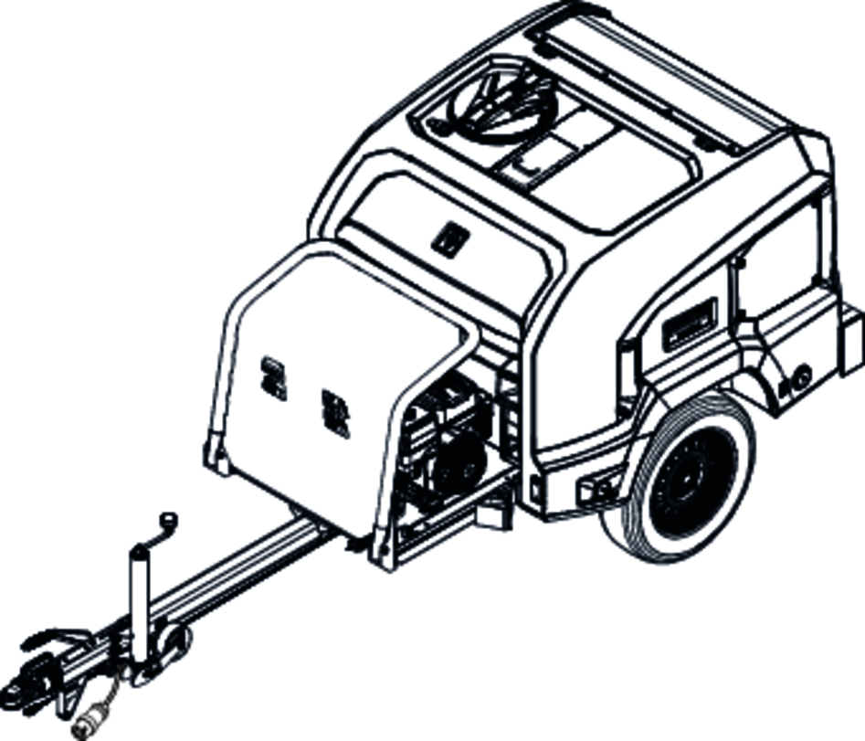
The device is specially designed for use in locations where an electrical power supply is not available.
The device is only intended for mobile (not stationary) operation.
 The packing materials can be recycled. Please dispose of packaging in accordance with the environmental regulations.
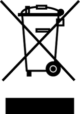 Electrical and electronic devices contain valuable, recyclable materials and often components such as batteries, rechargeable batteries or oil, which - if handled or disposed of incorrectly - can pose a potential danger to human health and the environment. However, these components are required for the correct operation of the device. Devices marked by this symbol are not allowed to be disposed of together with the household rubbish.
Current information on content materials can be found at: www.kaercher.de/REACH
Please do not allow engine oil, heating oil, diesel and petrol to enter the environment. Please protect the ground and dispose of old oil in an environmentally friendly manner.
Only use original accessories and original spare parts. They ensure that the appliance will run fault-free and safely.
Information on accessories and spare parts can be found at www.kaercher.com.
Check the contents for completeness when unpacking. If any accessories are missing or in the event of any shipping damage, please notify your dealer.
Observe the respectively applicable national regulations for liquid jet cleaners and accident prevention.
Liquid jet cleaners must be tested regularly. The results of the inspection must be recorded in writing.
Do not modify the device or accessories.
Danger of explosion.
Only fill the fuel specified in the operating instructions.
Only refuel with the engine switched off.
Do not refuel in confined spaces.
Smoking and open flames are prohibited.
Ensure that no fuel gets on hot surfaces during refuelling.
Close the fuel tank cap after refuelling.
Do not operate the device if fuel has been spilt. Move the device to another location and avoid generating sparks.
Store fuel only in approved containers.
Do not store fuel in the vicinity of open flames or devices having an ignition flame or that generate sparks (e.g. oven, heating boiler or water heater).
Do not spray start spray into the air filter.
Risk of fire.
Maintain a minimum distance of 2 m between inflammable objects and the muffler.
Do not operate the device in forests, bushy or grassy areas unless the exhaust pipe has been equipped with a spark catcher.
Keep grass and other soiling substances away from the cooling fins.
Do not operate the device if the fuel system is damaged or leaking. Check the fuel system regularly.
Allow the device to cool down before storing in closed rooms.
Danger of electric shock
Do not touch the spark plug or ignition lead when the device is in operation.
Danger of accident
Replace the tyres every 6 years at the latest if the vehicle is approved for speeds of up to 100 km/h.
Replace the tyres immediately if bulges or cracks are visible in the side wall or if the tread has become detached.
Health risk
Exhaust gases are toxic. Never breathe in the exhaust gases. Never operate the device in confined spaces. Ensure sufficient ventilation and extraction of the exhaust gases.
Make sure that no exhaust gases are emitted close to air vents.
Avoid repeated or prolonged contact with fuel or engine oil and do not inhale the fuel vapours.
Danger of burns
Do not touch any hot parts such as the muffler, cylinder or cooling fins.
Danger of hearing damage
Do not operate the device without a muffler. Check the muffler regularly and have a damaged muffler replaced.
Risk of damage
Use only spare parts from the original manufacturer.
Old fuel can lead to deposits in the carburettor and impair the engine performance. Use only new fuel.
Do not adjust any control springs or linkages that might increase the speed of the engine.
Do not operate the device with the air filter removed.
Do not pull the starter cord while the device is running.
Ensure adequate ventilation so that the device does not overheat.
Risk of fire, risk of explosion
Risk of asphyxiation
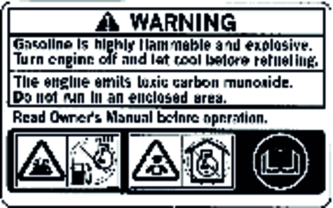
Petrol is highly inflammable and explosive.
The engine exhaust gas contains poisonous carbon monoxide.
Switch off the engine and allow it to cool down before refuelling.
Never allow the device to run in a confined space.
Read the operating instructions before starting the device.
Safety devices protect the user and may not be disabled or functionally circumvented.
The safety latch on the high-pressure gun prevents the high pressure water jet from being triggered unintentionally.
The pressure relief valve opens when the high-pressure gun is closed. This causes water to be returned from the high-pressure outlet to the suction side of the high-pressure pump. This prevents the maximum permissible working pressure from being exceeded.
The pressure relief valve is set and sealed at the factory. Only the Customer Service department is authorised to adjust the pressure relief valve.
The safety valve opens when the maximum permissible operating pressure is exceeded and the water flows into the open.
The safety valve is set and sealed at the factory. Only the Customer Service department is authorised to adjust the safety valve.
Only the Advanced version has this function.
The thermostat valve protects the high-pressure pump from overheating in circulation mode when the high-pressure gun is closes. The thermostat valve opens when the water temperature exceeds 80 °C and channels the hot water into the open.
At the three-way cock
 | Draining/filling the water reservoir |
 | Internal water supply, 1000 l |
 | External water supply |
 | Frost protection flushing position |
At the lifting eyelet (option)
 | DANGERRisk of injury The device can fall down and injure or kill persons. Read the safety instructions in thee operating instructions before slinging the device on a crane. Drain the reservoir before slinging the device on a crane, to avoid overloading the lifting eyelet. |

Risk of injury, risk of damage
Be aware of the weight of the device during transport.
Risk of damage
Protect the trigger of the high-pressure gun during transport.
Note: The driver driving the towing vehicle on public roads must ensure that he/she has the appropriate license for this (driving license class).
Unpredictable driving behaviour
With a partially filled water reservoir, the device can rock up or tip over under extreme steering movements or braking situations.
Drain or fill the water reservoir before driving.
Completely fill or completely drain the water reservoir.
On devices without a hose reel, unscrew the high-pressure hose from the high-pressure outlet and stow it in the device.
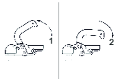
Pivot the front bar (option) forwards and lock in place.
Pull the rear tarpaulin (option) down an lock in place.
Use the support wheel to adjust the tow bar to the height of the towing hitch on the towing vehicle.
Attach the safety line to the towing vehicle.
Pull the coupling lever up (open).
Fit the tow bar onto the towing hitch ball.
Press the coupling lever down (close) until it lies parallel to the tow bar.
Plug in the connector for the vehicle lighting.
Use the crank to wind up the support wheel.
Ensure that the support wheel points toward the trailer when fully retracted.

Remove the chocks from the wheels and insert them into the holders.
Release the parking brake.
Check that the trailer lighting system (brake lights, indicator lights, tail lights, license plate light) is functioning correctly.
Check the running surfaces of the tyres for embedded objects.
Check the condition of the tyres.
Check the tyre pressure, see "Maintenance work".
Note: Note the locally applicable speed limits for vehicles with trailers and adhere to these.
Risk of injury
The device or objects placed on top can fall down and injure persons.
Observe the local regulations for accident prevention and the safety instructions.
Drain the water reservoir before transporting by crane.
Check the lifting gear for damage before each crane transport.
Lift the device only by the lifting eyelet.
Secure the lifting gear against unintentional unhooking of the load.
Do not transport any objects on the device during the lifting operation.
Transport the device only when you have been instructed in operation of the crane.
Do not stand under the suspended load.
Ensure that no persons are in the hazard zones of the crane.
Do not leave the device handing unattended on the crane.
Risk of injury
Check that the device, accessories, supply lines and connections are in a correct condition. Do not use the device if it is not in a correct condition.
Risk of damage
Malfunctions can occur and the device can be damaged if the device is not standing level.
Ensure that the device is standing level before starting up.
Apply the parking brake.
Use the crank to lower the support wheel.
Release the safety line from the towing vehicle.
Unplug the vehicle lighting connecting and plug it into the holder on the tow bar.
Use the chocks to secure the device against rolling away.
Uncouple the towing vehicle.
Align the device level using the support wheel.
Release and unhook both locks.
Pivot the front bar upwards.
Note: The EASY!Lock system connects components quickly and safely via a single turn of the quick-release thread.
Plug the high-pressure nozzle onto the spray lance.
Tighten the union nut hand-tight (EASY!Lock).
Connect the spray lance with the pressure and quantity control to the high-pressure gun and hand-tighten (EASY!Lock).
Connect the high-pressure hose to the high-pressure gun and hand-tighten (EASY!Lock).
Connect the high-pressure hose to the high-pressure outlet of the high-pressure pump or the hose reel (option) device and tighten hand-tight (EASY!Lock).
Clean the oil level in the engine.
Do not start up the device if the oil level is below the "MIN" mark.
Top up with oil if necessary, see "Care and maintenance".
Check the oil level at the high-pressure pump oil sight glass. Do not start up the device if the oil level is below the middle of the oil sight glass.
Top up with oil if necessary, see "Care and maintenance".
Refuel only outdoors.
See the "Technical data" for the fuel specification.
Shut down the engine.
Allow the motor to cool down.
Unscrew the fuel tank cap.
Fill petrol up a maximum of the lower edge of the filling nozzle.
Fit the fuel tank cap and screw tight.
Immediately wipe up any spilt petrol.
Fill the diesel fuel up to a maximum of the red ring in the filling nozzle.
Use diesel fuel conforming to EN 590 or diesel fuel with a maximum sulphur content of 5000 ppm.
Fit the fuel tank cap and screw tight.
Immediately wipe up any spilt diesel fuel.
Unsuitable detergents
Risk of injury
Use only KÄRCHER products.
Never fill with solvents (e.g. petrol, acetone, thinners).
Avoid contact with eyes and skin.
Observe the safety and handling instructions of the detergent manufacturer.
Health risk through incorrect handling of detergents
Adhere to the safety instructions stated on the detergent packaging.
Unsuitable detergents can damage the device and the object to be cleaned.
Use only detergents approved by KÄRCHER.
Observe the dosing recommendations and notes provided with the detergent.
Use detergents sparingly to help conserve the environment.
KÄRCHER detergents ensure fault-free operation. Ask us for a consultation, request our catalogue or our detergent information sheets.
Place the detergent canister in front of the device.
Insert the detergent suction filter into the detergent canister and lower it to the bottom.
Observe the following warnings when handling the batteries:
 | Observe notes in the instructions for the battery, on the battery and in these operating instructions. |
 | Wear eye protection. |
 | Keep acids and batteries away from children. |
 | Risk of explosion |
 | Fire, sparks, open flames and smoking are prohibited. |
 | Risk of acid burns |
 | First aid. |
 | Warning |
| Disposal |
| Do not throw batteries in the bin. |
Risk of explosion, risk of injury
Observe the safety instructions on the handling of batteries.
Observe the operating instructions of the charger manufacturer.
Remove the battery cover.
Disconnect the battery from the device.
Connect the plus cable of the charger to the plus terminal of the battery.
Connect the minus cable of the charger to the minus terminal of the battery.
Plug the mains plug of the charger into the socket.
Switch on the charger.
Charge the battery with the lowest possible charging current.
See the "Technical data" for the connection values.
Connect the water inlet to the water supply (e.g. a water tap) using a hose.
The device can be supplied with water from the water reservoir (internal water supply) or water from the water supply network (external water supply).
Turn the three-way cock to the "External water supply" position.
Open the water inlet.
Turn the three-way cock to the "Drain/fill water reservoir" position.
Open the water inlet.
Observe the filling level at the water reservoir filling level indicator.
Shut off the water supply when the desired filling level has been reached.
Unscrew the water supply hose from the device.
The water reservoir can also be filled via the filler opening.
Turn the filler opening cap anticlockwise and pivot it up.
Check that the sieve basket is fitted in the filler opening.
Fill the water reservoir with water via the filler opening. The water hose can be secured at the lashing eyelet.
Pivot the filler opening cap down and lock by turning it clockwise.
Turn the three-way cock to the "Internal water supply" position.
Risk of explosion
Do not spray inflammable liquids.
Risk of injury
Never operate the device without the spray lance installed. Check that the spray lance is firmly connected each time before use. The screw connection of the spray lance must be tightened hand tight.
Hold the high-pressure gun and spray lance firmly with both hands when working.
Never fasten the trigger and safety lever in the actuated position.
Do not use the high-pressure gun when the safety lever is damaged.
Actuate the safety lever and trigger.
The high-pressure gun opens.
Release the safety lever and trigger.
The high-pressure gun closes.
Risk of injury!
Switch off the device and actuate the trigger gun until the device is depressurised before changing the nozzle.
Lock the trigger gun by pushing the safety latch forward.
Change the nozzle.
Turn the fuel cock to the "ON" position.
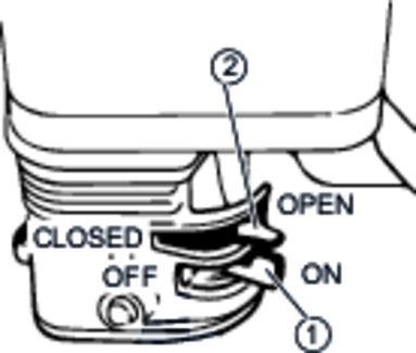
Push the choke lever to the "CLOSED" position if the engine is cold.
Turn the key-operated switch to the START position and hold in this position until the engine starts.
If the engine does not start within 5 seconds, release the key-operated switch and allow it to move to the "1/ON" position. Wait for 10 seconds before trying to start again.
When the engine starts, release the key-operated switch and allow it to move to the "1/ON" position.
Slowly move the choke lever to the "OPEN" position as the engine warms up.
Pivot the fuel cock down.
Turn the key-operated switch to the START position and hold in this position until the engine starts.
When the engine starts, release the key-operated switch and allow it to move to the "ON" position
If the engine does not start, wait for 30 seconds before trying to start again.
Unscrew the high-pressure nozzle from the spray lance.
Allow the device to run until the escaping water is free of air bubbles.
In the case of venting problems, allow the device to run for 10 seconds and then switch it off. Repeat the procedure several times.
Switch off the device.
Screw the high-pressure nozzle onto the spray lance.
Unlock the high-pressure gun by pushing the safety latch to the rear.
Open the trigger gun.
Risk of injury
If the spray lance detaches from the pressure/quantity control, a danger of injury to the operator exists due to a sharp high-pressure water jet.
Take care to ensure that the spray lance screw connection does not release when adjusting the pressure/quantity control.
Adjust the working pressure and flow rate by turning the pressure/quantity control at the high-pressure gun.
Replace the high-pressure nozzle in the spray lance with the low-pressure nozzle.
Set the detergent dosing valve to the desired concentration.
Spray the detergent sparingly on the dry surface and let it work for a while (do not let it dry).
Replace the low-pressure nozzle in the spray lance with the high-pressure nozzle.
Set the detergent dosing valve to "0".
Rinse off the loosened dirt with the high-pressure jet.
Release the lever of the high-pressure gun.
Note: The engine continues running at idling speed when the trigger of the high-pressure gun is released.
Switch off the engine if the interruption lasts more than a few minutes.
Actuate the high-pressure gun until the device is completely depressurised.
Push the safety latch of the high-pressure gun forward.
This secures the high-pressure gun against being unintentionally opened.
Set the detergent dosing valve to "0".
Flush the device clean with a running engine and opened high-pressure gun for at least 1 minute.
After operating with salty water (seawater) flush the device clean with tap water and an opened high-pressure gun for at least 2...3 minutes.
Close the high-pressure gun.
Turn the key-operated switch to "0/OFF".
Turn the fuel cock to the "OFF" position.
If using an external water supply, shut off the water supply.
Open the trigger gun until the device is completely depressurised.
Push the safety latch of the high-pressure gun forward.
This secures the high-pressure gun against being unintentionally opened.
If using an external water supply, disconnect the water supply hose from the device.
Risk of damage
Do not pull up the shutdown lever when the high-pressure gun is open.
Pull up the red shutdown lever until the engine stops.
Turn the key-operated switch to "0".
Pivot the fuel cock upwards.
If using an external water supply, shut off the water supply.
Open the trigger gun until the device is completely depressurised.
Push the safety latch of the high-pressure gun forward.
This secures the high-pressure gun against being unintentionally opened.
If using an external water supply, disconnect the water supply hose from the device.
Remove the water supply hose from the water inlet.
Turn the three-way cock to the "Drain/fill water reservoir" position.
Drain the water reservoir.
Remove the frost protection hose from the holder.
Connect the frost protection hose to the water inlet.
Insert the other end of the frost protection hose into a canister with anti-freeze liquid.
Turn the three-way cock to the "Frost protection flushing" position.
Remove the nozzle from the spray lance.
Start the engine.
Open the high-pressure gun and wait until anti-freeze escapes from the spray lance (water jet changes colour).
Insert the spray lance into the canister and flush the device in circulation mode for approximately 1 minute.
Pull the frost protection hose out of the canister.
Allow the device to continue running briefly until most of the anti-freeze has been expelled from the device. Do not run the device dry for longer than 1 minute.
Danger of injury from electric shock.
You can be injured by moving parts. The electrical voltage generated by the device can kill or injure you.
Remove the spark plug connector and disconnect the battery before performing any maintenance work.
Danger of burns.
Hot device components cause burns if touched.
Allow the device to cool down before working on it.
* See "Startup" for a description.
** See "Maintenance work" for a description.
Time & date | HD 9/23 Ge Tr1 | HD 9/23 De Tr1 | Activity | By whom |
|---|---|---|---|---|
Before each journey | X | X | Check the lighting. | Operator |
X | X | Check the tyre pressure and condition of the tyres. | Operator | |
Daily before startup | X | X | Check the condition of the oil in the high-pressure pump sight glass. Do not start up the device if the oil is milky. Notify Customer Service. | Operator |
X | X | Check the level of the oil in the high-pressure pump sight glass. Top up the oil if necessary. | Operator | |
X | X | Check the high-pressure hose for damage. Do not continue using damage high-pressure hoses. | Operator | |
X | X | Check the oil level in the engine and top up if necessary. | Operator | |
X | Check the engine for oil leaks | Operator | ||
X | Check the spark catcher (not included in the scope of delivery) for clogging. | Operator | ||
X | Check the fuel system for leaks. | Operator | ||
X | Check the air filter. | Operator | ||
X | X | Perform a general visual inspection of the device. | Operator | |
X | X | Check the piping system for leaks. | Operator | |
X | X | Check the water filter, clean if necessary. | Operator | |
X | X | Check the sieve basket in the filler opening of the water reservoir and clean if necessary. | Operator | |
X | X | Check the detergent suction filter, clean if necessary. | Operator | |
After the first 20 operating hours | X | Change the engine oil. | Operator | |
After the first 50 operating hours | X | Change the engine oil. | Operator | |
X | Check the engine oil filter, clean if necessary. | Operator | ||
X | X | Change the oil in the high-pressure pump. | Operator | |
Monthly | X | X | Clean the water filter. | Operator |
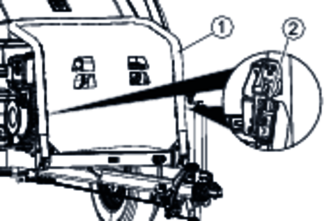
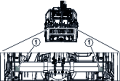
X | X | Check the fasteners between the engine and chassis for cracks. Have damaged fasteners replaced by Customer Service. | Operator | |
Every 50 operating hours or 3 months | X | Clean the fuel sieve in the fuel tank filling nozzle. | Operator | |
X | Clean the air filter. | Operator | ||
Every 100 operating hours or half-yearly | X | Change the engine oil. | Operator | |
X | X | Clean the air filter. | Operator | |
X | Clean the settling cup. | Operator | ||
X | Check the spark plug and adjust if necessary. | Operator | ||
X | Clean the spark catcher (not included in the scope of delivery). | Operator | ||
X | Clean the fuel tank and fuel filter. | Customer Service | ||
Every 200 operating hours | X | Change the engine oil. | Operator | |
X | Clean the fuel tank. | Operator | ||
X | Replace the fuel filter. | Operator | ||
Every 300 operating hours or annually | X | Replace the air filter insert. | Operator | |
X | Replace the spark plug. | Operator | ||
X | Check the idling speed and adjust if necessary. | Customer Service | ||
X | Check the valve play in the engine and adjust if necessary. | Customer Service | ||
Every 400 operating hours | X | Check the valve play in the engine and adjust if necessary. | Customer Service | |
X | Check the engine oil filter, clean if necessary. | Operator | ||
Every 500 operating hours | X | Clean the engine combustion chamber. | Customer Service | |
X | Replace the air filter insert. | Operator | ||
Every 600 operating hours | X | X | Lubricate the inertia brake on the tow bar. | Operator |
Annually | X | X | Change the oil in the high-pressure pump. | Operator |
X | X | Have the annual inspection for high-pressure cleaners performed by the Customer Service department. | Customer Service | |
Every 1000 operating hours | X | Check the engine compression. | Customer Service | |
Every 1500 operating hours | X | Check and clean the fuel injection nozzle. | Customer Service | |
Every 2000 operating hours or 2 years | X | X | Replace the fuel hoses. | Customer Service |
Shut off the water inlet.
Unscrew the filter cup.
Pull the filter insert downwards and off.
Clean the filter insert and filter cup.
Re-install the filter insert.
Screw on the filter cup again and tighten.
Provide a catch pan for at least 1 litre of oil.
Remove the oil reservoir cap
Unscrew the oil drain plug.
Drain the oil into the catch pan.
Dispose of the old oil in accordance with the environmental regulations.
Clean the oil drain screw, then screw it in again and tighten.
Fill with new oil slowly so that air bubbles can escape, until the level is in the middle of the oil sight glass.
Note: The oil type and filling quantity are specified in the section "Technical data".
Fit the oil reservoir cap.
Use a commonly available grease gun to inject the appropriate grease into both grease nipples.

Place the device on a level surface.
Connect the tyre pressure gauge device to the tyre valve.
Check the type pressure (see "Technical data") and correct if necessary.
Danger of accident
Danger through poor recognisability.
Be sure to always wear warning clothing when performing repairs in the danger zone of flowing traffic.
Place the device on a level surface.
Check that the ground is stable.
Use both chocks to secure the device against rolling away.
Apply the parking brake.
Check the tyres:
Check the tyre running surfaces for embedded objects.
Remove any objects found.
Seal the tyres with a commonly available tyre repair kit.
Note: Observe the recommendations of the respective manufacturer. Driving can only be continued when the stipulations of the product manufacturer are adhered to. Change the wheel or tyre as soon as possible.
Fit the jack (not included in the scope of delivery) under the lifting point.
Loosen the wheel nuts slightly.
Lift the device with the jack.
Unscrew the wheel nuts.
Remove the wheel.
Fit the spare wheel.
Screw in the wheel nuts and tighten slightly.
Lower the device with the jack.
Tighten the wheel nuts in a diagonal sequence, tightening torque 110...120 Nm.
Position the device on a level surface.
Unscrew the oil dipstick.
Wipe off the oil dipstick.
Insert the oil dipstick as far as it will go, but do not screw in.
Pull out the oil dipstick. The oil level must lie in the marked section of the oil dipstick.
Top up the engine oil if the level is too low.
Screw in and tighten the oil dipstick.
Unscrew the wing nut.
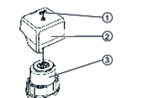
Remove the cover.
Check the air filter for soiling, clean if necessary.
Fit the cover.
Screw on the wing nuts and tighten.
Unscrew the wing nuts on the cover.

Remove the cover.
Unscrew the air filter wing nuts.
Remove the air filter insert.
Remove the foam filter insert from the paper filter insert.
Check both air filter inserts for damage.
Replace any damaged air filter inserts.
Clean any reused air filter inserts.
Knock the paper filter insert a few times on a hard surface to clean it or blow it out from the inside with compressed air (maximum 0.2 MPa).
Foam filter insert:
Clean in warm soapy water.
Rinse with clear water.
Or clean in a non-inflammable solvent.
Allow to dry.
Immerse in clean engine oil.
Press out the excess oil.
Wipe off the inner side of the cover and air filter housing with a damp cloth. Take care to ensure that no dirt enters the engine.
Fit the foam filter insert on the paper filter insert.
Fit the air filter insert into the air filter housing.
Ensure that the seal is correctly fitted between the air filter housing and the engine.
Fit the air filter wing nuts and tighten.
Fit the cover.
Fit the cover wing nuts and tighten.
Perform the oil change on a warm engine so that the oil drains better.
Shut down the engine.
Position the device on a level surface.
Place a suitable catch pan for the old oil under the engine.
Unscrew the oil dipstick.
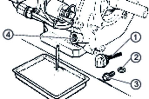
Unscrew the oil drain plug and remove together with the seal.
Allow the oil to drain completely.
Screw in and tighten the oil drain screw with a new seal.
Dispose of the old oil in accordance with the environmental regulations.
Fill new engine oil (see "Technical data") up to the lower edge of the filler opening.
Screw in and tighten the oil dipstick.
Turn the fuel cock to the "OFF" position.
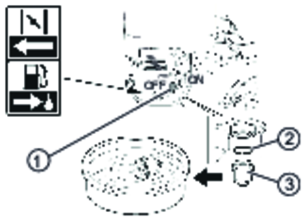
Unscrew the settling cup.
Remove the O-ring.
Clean the settling cup in a non-inflammable solvent.
Thoroughly dry the settling cup.
Fit the O-ring into the housing.
Screw in and tighten the settling cup.
Turn the fuel cock to the "ON" position.
Check that the settling cup is tightly seated.
Turn the fuel cock to the "OFF" position.
Pull off the spark plug connector.
Clean the region around the spark plug to prevent dirt from entering the engine when the spark plug is removed.
Unscrew the spark plug with a 13/16" spark plug wrench.
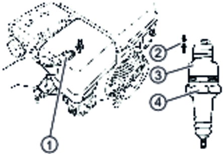
Replace a spark plug that has worn electrodes or a broken insulator.
Check the electrode gap of the spark plug. Target value 0.7...0.8 mm.
Check the spark plug seal for damage.
Risk of damage
A loose spark plug can overheat and damage the engine. An overtightened spark plug can damage the thread in the engine.
Observe the following instructions for tightening the spark plug.
Carefully screw the spark plug in by hand. Do not cross the thread.
Screw the spark plug all the way in using the plug spanner and the tighten as follows.
Tighten a used spark plug by an additional 1/8...1/4 turn.
Tighten a new spark plug by an additional 1/2 turn.
Plug on the spark plug connector.
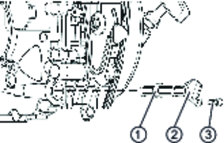
Unscrew both nuts from the silencer.
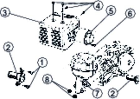
Remove the silencer from the engine.
Unscrew the 3 screws at the baffle plate.
Unscrew the 4 screws at the heat shield.
Remove the cover heat shield.
Unscrew both screws at the spark catcher.
Remove the spark catcher from the silencer.
Brush any deposits off the spark catcher.
Do not damage the spark catcher.
Replace the spark catcher if it has cracks or holes.
Install the parts again in the reverse sequence.
Position the device on a level surface.
Unscrew the oil dipstick.
Wipe off the oil dipstick.
Insert the oil dipstick as far as it will go, but do not screw in.
Pull out the oil dipstick. The oil level must lie in the marked section of the oil dipstick.
Top up the engine oil if the level is too low.
Screw in and tighten the oil dipstick.
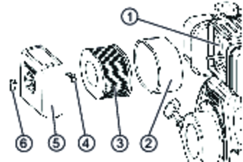
The spark catcher must be cleaned when the diffusor discs are coated with soot.
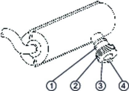
Unscrew the nuts.
Remove the end cap and diffusor discs from the spark catcher.
Remove soot deposits from all parts.
Reassemble the spark catcher again.
Perform the oil change on a warm engine so that the oil drains better.
Shut down the engine.
Position the device on a level surface.
Place a suitable catch pan for the old oil under the engine.
Unscrew the oil dipstick.
Unscrew and remove the oil drain plug.
Allow the oil to drain completely.
Screw in and tighten the oil drain plug (19,6...23,5 Nm).
Dispose of the old oil in accordance with the environmental regulations.
Fill new engine oil (see "Technical data") up to the lower edge of the filler opening.
Screw in and tighten the oil dipstick.
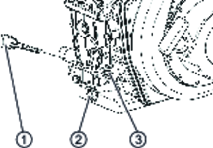
Unscrew the screw.
Pull out the cover together with the oil filter.
Separate the oil filter from the cover.
Clean the oil filter and replace it if damaged.
Fit the oil filter in the engine.
Fit the cover and check it for a correct fit.
Screw in and tighten the screw.
Check the oil level and top up with oil if necessary.
Start the engine and allow it to warm up for 5 minutes.
Check the engine for oil leaks.
Allow the engine to stand for 10 seconds.
Check the oil level again.
Unscrew the wing nuts on the cover.
Remove the cover.
Unscrew the air filter wing nuts.
Remove the air filter insert.
Remove the foam filter insert from the paper filter insert.
Check both air filter inserts for damage.
Replace any damaged air filter inserts.
If reusing, blow out the air filter insert from the inside with compressed air (0.29...0.49 MPa). Keep the air pressure as low as possible to avoid damaging the insert.
Wipe off the inner side of the cover and air filter housing with a damp cloth. Take care to ensure that no dirt enters the engine.
Fit the paper filter insert into the air filter housing.
Fit the foam filter insert on the paper filter insert.
Fit the air filter wing nuts and tighten.
Fit the cover.
Fit the cover wing nuts and tighten.
Place a suitable collection container under the fuel tank for catching the fuel from the fuel tank.
Unscrew the fuel tank cap.
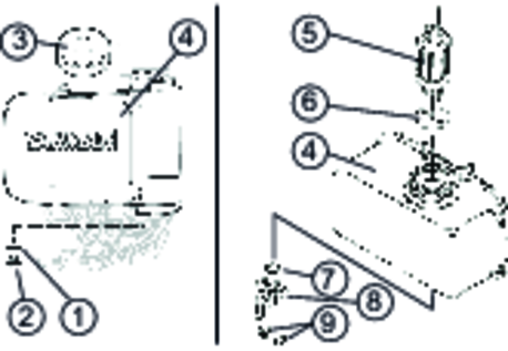
Unscrew fuel oil drain plug and remove together with the seal.
Dispose of the seal.
Collect the fuel in the placed container.
Unscrew both nuts.
Remove the fuel cock together with the O-ring.
Dispose of the O-ring.
Pull the fuel filter and seal out of the fuel tank filler opening and dispose of these.
Fit a new fuel filter with a new seal in the fuel tank.
Fit a new O-ring in the fuel cock.
Fit the fuel cock on the fuel tank and fasten with both nuts.
Screw the fuel drain plug together with a new seal into the fuel tank and tighten it.
Fill the tank with fuel.
Fit the cap and screw into place.
Have all checks and work on electrical parts performed by an expert.
In case of any malfunctions not mentioned in this chapter, contact the authorised Customer Service.
The engine does not start.
Remedy:
Open the fuel cock.
Fill the tank with fuel.
Check the oil level and top up if necessary.
Pivot the choke lever to the "CLOSED" position if the engine is cold (only for HD 9/23 Ge Tr1).
Check the spark plug (only for HD 9/23 Ge Tr1).
Check the settling cup (only for HD 9/23 Ge Tr1).
Check the fuel filter. Replace the filter if the fuel filter is dirty (only for HD 9/23 De Tr1).
The electric starter does not turn or turns too slowly
Remedy:
Charge the battery.
Check the battery connection, clean the connection terminals and battery terminals if necessary.
Check the fuse (only for HD 9/23 Ge Tr1), see "Checking the fuse".
Low engine performance
Remedy:
Check the air filter.
Drain the fuel tank and carburettor (only for HD 23 Ge Tr1). Refuel with fresh fuel.
High soot content in the exhaust gas (only for HD 9/12 De Tr1)
Remedy:
Check the air filter for soiling, clean if necessary.
Refuel with the prescribe fuel (see "Technical data").
High-pressure pump not building up pressure
Remedy:
Check the engine speed (see "Technical data").
Fit the high-pressure nozzle to the spray lance.
Set the detergent dosing valve to "0".
Adjust the pressure/quantity control.
Clean or replace the high-pressure nozzle.
Clean the water filter.
Vent the high-pressure pump (see chapter "Startup/device").
If using the internal water supply, check the water reservoir filling level.
If using an external water supply, check the water supply volume (see "Technical data").
Check the supply lines to the high-pressure pump for leaks.
The pump is leaking
.Up to 3 drops of water per minute are permissible.
Remedy:
In case of more serious leaks, have the device checked by Customer Service.
Detergent is not sucked in
Remedy:
Fit the low-pressure nozzle to the spray lance.
Open, check and clean the detergent dosing valve.
Clean the detergent suction filter.
Unscrew the screw.
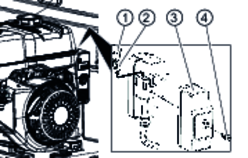
Remove the housing cover.
Pull off the fuse cover.
Pull out the fuse and check it.
Risk of damage, risk of fire
Installing a fuse of a higher rating than prescribed can lead to severe damage to the electronics and possibly also cause a fire.
Always replace the fuse with a fuse of the same rating.
The warranty conditions issued by our relevant sales company apply in all countries. We shall remedy possible malfunctions on your appliance within the warranty period free of cost, provided that a material or manufacturing defect is the cause. In a warranty case, please contact your dealer (with the purchase receipt) or the next authorised customer service site.
(See overleaf for the address)
Internal combustion engine | |
Engine type | Honda GX 390 |
Cylinder | 1 |
Cycles | 4 |
Engine capacity | 389 cm3 |
Engine performance | 9,5/13 kW/PS |
Engine speed | 3250 1/min |
Fuel type | Petrol, unleaded |
Fuel tank capacity | 6,1 |
Fuel consumption at full load | 3,5 l/h |
Engine oil volume | 0,9 l |
Oil type | 15W40 |
Spark plug type | BPR6ES, W20EPR-U |
Battery | |
Battery capacity | 41 Ah |
Working voltage of the battery | 12 V |
Water connection | |
Feed pressure (max.) | 1 MPa |
Input temperature (max.) | 60 °C |
Input amount (min.) | 16,7 l/min |
Suction height (max.) | 1 m |
Minimum water supply hose length | 7,5 m |
Minimum water supply hose diameter | 3/4 in |
Water reservoir capacity | 1000 l |
Device performance data | |
Nozzle size of standard nozzle | 050 |
Nozzle size of low-pressure nozzle | 250 |
Operating pressure | 4...23 MPa |
Operating pressure (max.) | 27 MPa |
Water flow rate | 6,7...15,5 l/min |
Thermostat valve opening temperature | 80 °C |
Detergent flow rate | 0...0,8 l/min |
High-pressure gun recoil force | 55 N |
Dimensions and weights | |
Typical operating weight, tank empty | 440...570 kg |
Typical operating weight, tank full | 1390...1520 kg |
Length | 3380 mm |
Width | 1500 mm |
Height | 1435 mm |
Pump oil volume | 0,35 l |
Oil type | 15W40 Type |
Tyre size | 185 R 14 C |
Load capacity index | 104 |
Speed rating | N |
Wheel size/rim shape | 5,5 J x 14 |
Offset | 30 |
Tyre pressure | 0,45 MPa |
Inertia brake | X |
Determined values in acc. with EN 60335-2-79 | |
Hand-arm vibration value | <2,5 m/s2 |
Uncertainty K | 0,7 m/s2 |
Sound pressure level | 90 dB(A) |
Uncertainty KpA | 3 dB(A) |
Sound power level LWA + uncertainty KWA | 107 dB(A) |
Internal combustion engine | |
Engine type | Yanmar L100V |
Cylinder | 1 |
Cycles | 4 |
Engine capacity | 435 cm3 |
Engine performance | 7,4/10 kW/PS |
Engine speed | 3250 1/min |
Fuel type | Diesel |
Fuel tank capacity | 5,4 |
Fuel consumption at full load | 2,0 l/h |
Engine oil volume | 1,2 l |
Oil type | 15W40 |
Spark plug type | - |
Battery | |
Battery capacity | 41 Ah |
Working voltage of the battery | 12 V |
Water connection | |
Feed pressure (max.) | 1 MPa |
Input temperature (max.) | 60 °C |
Input amount (min.) | 16,7 l/min |
Suction height (max.) | 1 m |
Minimum water supply hose length | 7,5 m |
Minimum water supply hose diameter | 3/4 in |
Water reservoir capacity | 1000 l |
Device performance data | |
Nozzle size of standard nozzle | 050 |
Nozzle size of low-pressure nozzle | 250 |
Operating pressure | 4...23 MPa |
Operating pressure (max.) | 27 MPa |
Water flow rate | 6,7...15,5 l/min |
Thermostat valve opening temperature | 80 °C |
Detergent flow rate | 0...0,8 l/min |
High-pressure gun recoil force | 55 N |
Dimensions and weights | |
Typical operating weight, tank empty | 440...570 kg |
Typical operating weight, tank full | 1390...1520 kg |
Length | 3380 mm |
Width | 1500 mm |
Height | 1435 mm |
Pump oil volume | 0,35 l |
Oil type | 15W40 Type |
Tyre size | 185 R 14 C |
Load capacity index | 104 |
Speed rating | N |
Wheel size/rim shape | 5,5 J x 14 |
Offset | 30 |
Tyre pressure | 0,45 MPa |
Inertia brake | X |
Determined values in acc. with EN 60335-2-79 | |
Hand-arm vibration value | <2,5 m/s2 |
Uncertainty K | 0,7 m/s2 |
Sound pressure level | 90 dB(A) |
Uncertainty KpA | 3 dB(A) |
Sound power level LWA + uncertainty KWA | 107 dB(A) |
Declaration of Conformity |
We hereby declare that the machine described below complies with the relevant basic safety and health requirements in the EU Directives, both in its basic design and construction as well as in the version placed in circulation by us. This declaration is invalidated by any changes made to the machine that are not approved by us.
Product: High-pressure cleaner
Type: 1.524-xxx
Currently applicable EU Directives2006/42/EC (+2009/127/EC)
2000/14/EC
2014/30/EU
Harmonised standards usedEN 60335-1
EN 60335-2-79
EN 1829-1
EN 1829-2
EN ISO 12100
EN 13309: 2010
EN 55012: 2007 + A1: 2009
EN 62233: 2008
Conformity evaluation procedure used2000/14/EC: Appendix V
Sound power level dB(A)Measured: 105
Guaranteed: 107
The signatories act on behalf of and with the authority of the company management.

Documentation supervisor:
S. Reiser
Alfred Kärcher SE & Co. KG
Alfred-Kärcher-Str. 28 - 40
71364 Winnenden (Germany)
Ph.: +49 7195 14-0
Fax: +49 7195 14-2212
Winnenden, 2021/02/01
Declaration of Conformity (UK) |
We hereby declare that the product described below complies with the relevant provisions of the following UK Regulations, both in its basic design and construction as well as in the version put into circulation by us. This declaration shall cease to be valid if the product is modified without our prior approval.
Product: High-pressure cleaner
Type: 1.524-xxx
Currently applicable UK RegulationsS.I. 2008/1597 (as amended)
S.I. 2001/1701 (as amended)
S.I. 2016/1091 (as amended)
S.l. 2016/1105 (as amended)
Designated standards usedEN 60335-1
EN 60335-2-79
EN 1829-1
EN 1829-2
EN ISO 12100
EN 13309: 2010
EN 55012: 2007 + A1: 2009
EN 62233: 2008
Applied conformity assessment procedureS.I. 2001/1701 (as amended): Schedule 8
Sound power level dB(A)Measured: 105
Guaranteed: 107
The signatories act on behalf of and with the authority of the company management.
Documentation supervisor:
S. Reiser
Alfred Kärcher SE & Co. KG
Alfred-Kärcher-Str. 28 - 40
71364 Winnenden (Germany)
Ph.: +49 7195 14-0
Fax: +49 7195 14-2212
Winnenden, 2021/02/01

2-2-NN-A4-GS-03323