BD 70/75 W Classic BpBD 80/100 W Classic BpBR 75/75 W Classic BpBR 85/100 W Classic Bp
59685040 (07/22)
59685040 (07/22)
 Read these original operating instructions and the enclosed safety instructions before using the device for the first time. Proceed accordingly.
Keep both books for future reference or for future owners.
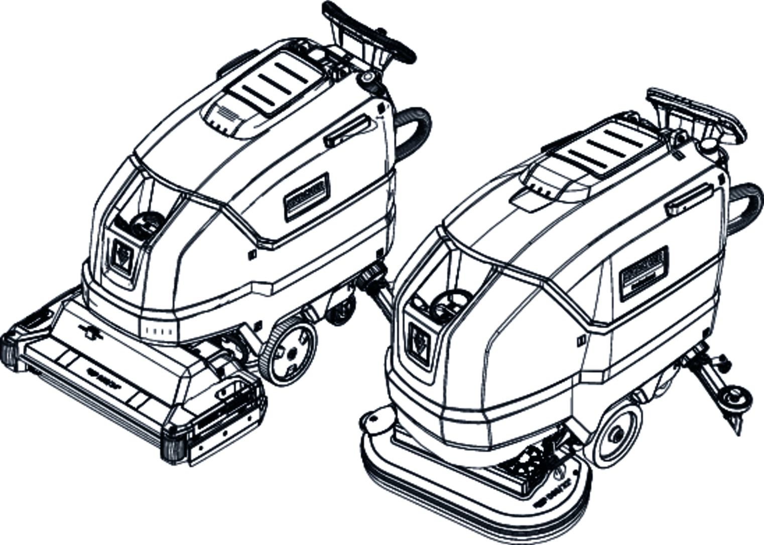
This scouring and vacuum machine is used for wet cleaning of level floors.
The device can be adjusted to suit the respective cleaning task by setting the water volume and detergent volume appropriately. The detergent dosing is adjusted via the amount added to the tank.
The working width and the capacity of the fresh and waste water tanks (see chapter "Technical data) enable effective cleaning with a long working time.
The device has a drive motor.
The device can be equipped with various accessories to suit the respective cleaning task. Request a copy of our catalogue or visit our Internet website at www.kaercher.com.
This device is suitable for commercial and industrial use, e.g. in hotels, schools, hospitals, factories, shops, offices, and rental companies. Use the device only in accordance with the information in these operating instructions.
The device may only be used for cleaning smooth surfaces that are insensitive to water and polishing.
The device is not suitable for cleaning frozen floors (e.g. in cold stores).
The device is not suitable for use in potentially explosive environments.
The device is approved for operation on surfaces with a maximum slope (see chapter
 The packing materials can be recycled. Please dispose of packaging in accordance with the environmental regulations.
 Electrical and electronic appliances contain valuable, recyclable materials and often components such as batteries, rechargeable batteries or oil, which - if handled or disposed of incorrectly - can pose a potential threat to human health and the environment. However, these components are required for the correct operation of the appliance. Appliances marked by this symbol are not allowed to be disposed of together with the household rubbish.
Current information on content materials can be found at: www.kaercher.com/REACH
The warranty conditions issued by our relevant sales company apply in all countries. We shall remedy possible malfunctions on your appliance within the warranty period free of cost, provided that a material or manufacturing defect is the cause. In a warranty case, please contact your dealer (with the purchase receipt) or the next authorised customer service site.
(See overleaf for the address)
Only use original accessories and original spare parts. They ensure that the appliance will run fault-free and safely.
Information on accessories and spare parts can be found at www.kaercher.com.
Check the contents for completeness when unpacking. If any accessories are missing or in the event of any shipping damage, please notify your dealer.
Before using the device for the first time, read and observe these operating instructions and the accompanying brochure: Safety information for brush cleaning units spray retraction devices, No. 5.956-251.0.
The device is approved for operation on surfaces with a specified limited slope (see Chapter
Risk of injury!
Device may tip over on sloping surfaces.
Do not operate the device on sloping surfaces.
The device may only be operated when the hood and all covers are closed.
Missing or modified safety devices!
Safety devices are provided for your own protection.
Do not bypass, remove or render ineffective any safety devices.
The device switches off when the safety switch is released.
Pulling the key out of the key-operated switch secures the device against unauthorised use.
Observe the following warnings when handling the batteries:
 | Observe notes in the instructions for the battery, on the battery and in these operating instructions. |
 | Wear eye protection. |
 | Keep acids and batteries away from children. |
 | Risk of explosion |
 | Fire, sparks, open flames and smoking are prohibited. |
 | Risk of acid burns |
 | First aid. |
 | Warning |
| Disposal |
| Do not throw batteries in the bin. |
** Not in scope of delivery
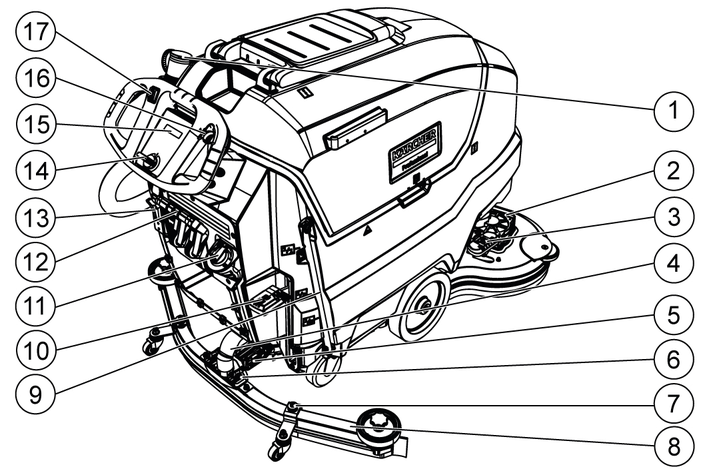
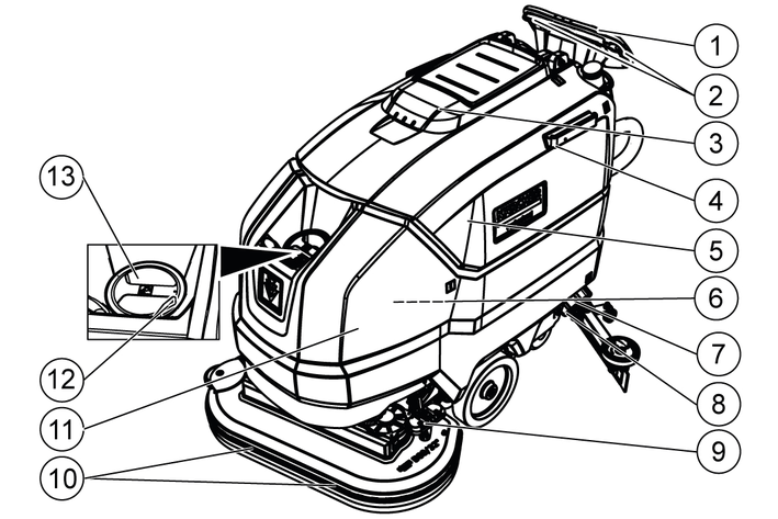
Control elements for the cleaning process are yellow.
Control elements for maintenance and servicing are light grey.
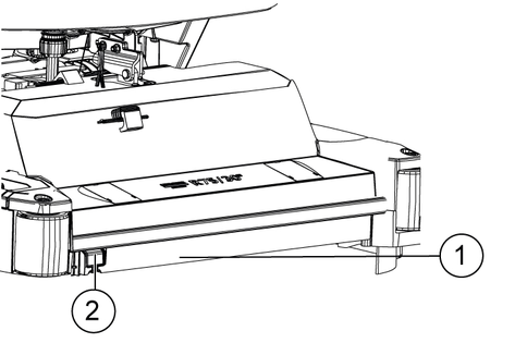
 | Fresh water tank drain opening |
 | Waste water tank drain opening |
 | Increased cleaning head contact pressure |
 | Battery access |
 | Fresh water tank filling level (50%) |
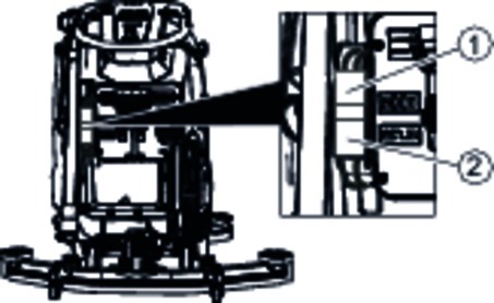
 | Insert the charger plug here |
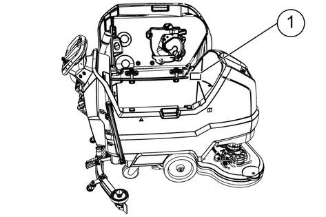
 | Lashing point |
 | * Mop holder |
 | ATTENTIONIncorrect socket Risk of damage DO NOT insert the charger plug here |
 | Normal cleaning head contact pressure |
 | Raise the cleaning head |
 | Pedal for raising/lowering the cleaning head |
 | Brush replacement pedal |
* optional
Remove the carton.
Remove the straps.
Remove the wooden blocks fastened to the pallet by screws.
Using the 3 upper reinforcing boards of the carton packaging and the securing board screwed laterally on the pallet, place a ramp in front of the pallet and secure it using board pallet screws.
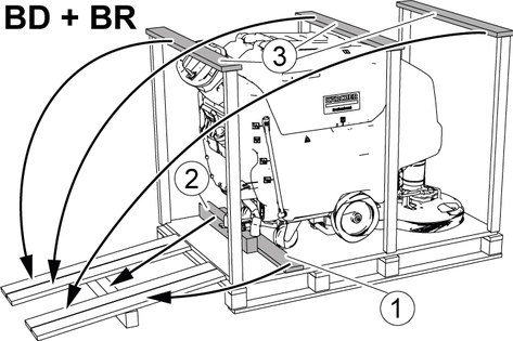
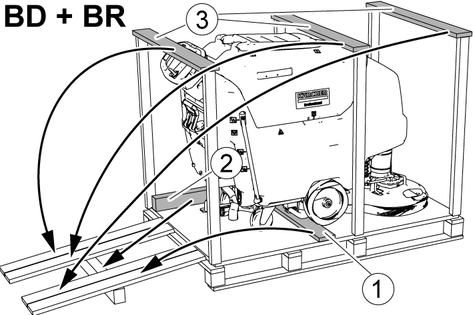
Push the beam which has been unscrewed from the pallet under the ramp for support and screw into place.
Press the cleaning head lever down and latch it in place.
Only for BD 80/100 and BR 85/100: Press the brake lever down.
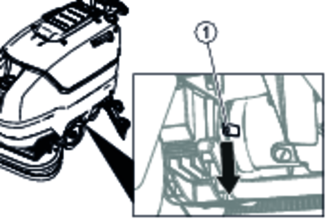
For BD 70/75 and BR 75/75, there is no brake. Releasing the brake is not necessary with this device.
Pull the device backwards off the pallet.
Only for BD 80/100 and BR 85/100: Press the brake lever up.
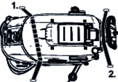
Insert the suction bar in the suction bar mount.
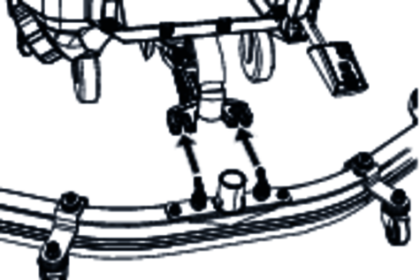
Tighten the wing nuts.
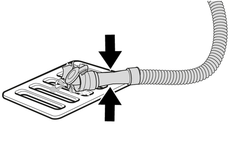
Fit the suction hose.
Description | Order no. | Volume (m3)* | Airflow (m3/h)** |
|---|---|---|---|
Only BD 70/75 W 115 Ah - maintenance-free | 2.815-091.0 1) | 1.98 | 0.792 |
170 Ah - maintenance-free | 2.815-092.0 2) | 2.31 | 0.924 |
180 Ah - maintenance-free | 2.815-101.0 3) | 4.785 | 1.914 |
* Minimum volume of the battery charging room
** Minimum airflow between battery charging room and environment
For initial installation, an additional battery installation kit is required:
2638-198.0
2638-162.0
2638-106.0
Description | Order no. | Volume (m3)* | Airflow (m3/h)** |
|---|---|---|---|
170 Ah - maintenance-free | 2.815-092.0 1) | 2.31 | 0.924 |
180 Ah - maintenance-free | 2.815-101.0 2) | 4.785 | 1.914 |
240 Ah - maintenance-free | 2.815-102.0 2) | 6.27 | 2.508 |
285 Ah - maintenance-free | 2.815-095.0 3) | 11.88 | 4.752 |
* Minimum volume of the battery charging room
** Minimum airflow between battery charging room and environment
For initial installation, an additional battery installation kit is required:
2638-162.0
2638-106.0
2638-197.0
Danger of burns due to acid leakage!
Only fill the battery with water when it is discharged.
When handling battery acid, use safety goggles and immediately rinse out any acid splashes on the skin or clothing with water.
Risk of damage to the batteries!
Using water with additives will void the battery's warranty.
Top up the batteries using only distilled or desalinated water (EN 50272-T3).
Do not use any foreign additives or touch-up agents.
Add distilled water one hour before the charging process comes to an end. Observe the correct acid level according to the battery label.
All cells must produce gas at the end of the charging process.
Risk of damage from AGM and gel batteries!
Opening or drilling the battery housing will damage an AGM or gel battery. It must then be replaced.
Do not open the battery housing and do not drill any holes.
Do not cover the pressure relief valve and do not change it.
Only charge AGM and gel batteries using the specified chargers, see chapter: Charging the battery.
Risk of injury due to the device tipping over!
Device may tip over when removing and installing batteries.
Ensure that the device is positioned stably when removing and installing the batteries.
Risk of damage to the control electronics!
The control electronics can be destroyed by reversing the polarity of the battery connections.
Take care to ensure the correct polarity when connecting the batteries.
Danger to life from fire or explosion if batteries are deeply discharged!
Incorrect charging of deeply discharged batteries can cause a fire.
Do not start the device if the battery is deeply discharged.
Make sure that the battery is charged before starting the system.
Drain the waste water.
Pivot the waste water tank upwards.
Place the battery in the device as shown. Important: Push the batteries all the way back!
BD 80/100 and BR 85/100
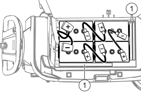
170 Ah, 2.815-092.0
180 Ah, 2.815-101.0
240 Ah, 2.815-105.0
285 Ah, 2.815-095.0
BD 70/75 and BR 75/75
115 Ah, 2.815-091.0
170 Ah, 2.815-092.0
180 Ah, 2.815-101.0
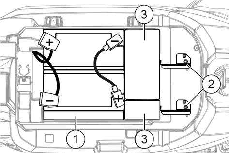
Insert a spacer between the right batteries and the fresh water tank,
for 115 Ah battery set: 1 piece lengthwise flat.
for battery sets other than 115 Ah: 2 pieces lengthwise upright on top of each other.
For BD 70/75 with 115 Ah battery set: Insert the 4 additional weights.
Attach the battery fastener, to do so
for BD 70/75: Install the 2 battery holders and for 115 Ah: Tighten at the left and middle threaded holes.For BR 75/75 and BD 70/75: 170 Ah / 180 Ah: Tighten at the right and middle threaded holes.
For BD 80/100 and BR 85/100: Insert one or two spacers flat lengthwise or vertically between the front batteries and the fresh water tank so that the batteries cannot slip forward.
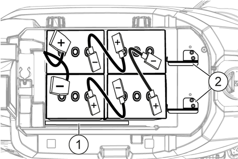
Connect the poles to the connection cables from the battery installation kit.
Clamp the connecting cables on the (+) and (‑) battery terminals that are still free.
Connect the device-side battery connector to the battery-side battery connector.
Pivot the waste water tank downwards.
Risk of injury due to the device tipping over!
Device may tip over when removing and installing batteries.
Ensure that the device is positioned stably when removing and installing the batteries.
Turn the key-operated switch to "0" and remove the key.
Disconnect the battery plug.
Drain the waste water.
Pivot the waste water tank upwards.
Disconnect the device-end cable from the negative terminal of the battery.
Disconnect the remaining cables from the batteries.
For BD 80/100: Remove the spacer(s) between the front batteries and the fresh water tank.
For 115 Ah battery set: Take out the additional weights.
Remove the batteries.
Dispose of the used batteries in accordance with statutory provisions.
Risk of injury from charger!
Electric shock due to improper use of the charger!
Adhere to the mains voltage and fuse values specified on the device type plate.
Only use the charger in dry rooms with sufficient ventilation.
Danger of explosion due to battery!
Gases accumulate under the tank during the charging process.
Pivot the waste water tank upwards before charging low-maintenance batteries.
Risk of damage due to unsuitable charger!
Do not connect the charger to the device-side battery connector.
Use only a charger suitable for the type of battery installed.
Read the operating instructions of the charger manufacturer and observe the safety instructions in particular.
Battery set | Capacity | Charger |
|---|---|---|
2.815-091.0 | 115 Ah | 6654-367.0 |
2815-092.0 | 170 Ah | 6654-436.0 |
2815-101.0 | 180 Ah | 6654-434.0 |
2815-105.0 | 240 Ah | 6654-437.0 |
2815-095.0 | 285 Ah | 6654-419.0 |
The average charging time is approx. 10-15 hours.
The device cannot be used during the charging process.
The device has deep discharge protection, i.e. the brush motor and turbine are switched off automatically when the permitted minimum capacity level is reached.
Drive the device directly to the charger and do not drive on slopes.
Pull out the device-side battery connector.
Connect the battery-side battery connector to the charger.
Plug the mains plug of the charger into the socket.
Carry out the charging process in accordance with the operating instructions for the charger.
Connect the device-side battery connector to the battery-side battery connector.
Risks during operation
Danger of injury
Release the safety switch in the case of danger.
Risk of damage to the device!
If unsuitable detergents are used, the device may get damaged.
Use only recommended detergents. The operator carries all increased risks relating to operational safety and increased risk of accidents if using other detergents.
Use only detergents free of solvents, salt and hydrofluoric acid.
Adhere to the safety instructions stated on the detergent packaging.
Do not use heavily foaming detergent.
Application | Detergent |
|---|---|
Floor maintenance cleaner extra low foaming with EU Ecolabel | APPROX. 50 C |
Highly wetting universal cleaner | RM 756 |
Intensive alcohol cleaner for floors and surfaces. Well-suited for hard rock such as granite | RM 755 |
Fine stone cleaner, surfactant-free | RM 753 |
Universal decoater, suitable for linoleum | RM 754 |
| Acidic vending machine basic cleaner. Suitable for sanitary areas and construction cleaning | RM 751 |
Industrial maintenance cleaner | RM 69 |
Industrial basic cleaner and alkaline decoater | RM 752 |
Surface disinfectant cleaner | RM 732 |
Fill the detergent into the fresh water tank.
Note: The cap for the fresh water tank filling hole can be used for measuring the correct quantity of detergent. It has a measuring scale marked on the inner side.
Adjust the water volume via the regulating knob to suit the degree of soiling of the floor covering.
Perform initial cleaning tests with a low water volume. Increase the water volume step by step until achieving the desired cleaning result.
The cleaning head continues operating without a liquid supply if the fresh water tank is empty.
The inclination must be adjusted so that the suction lips of the suction bar make even contact with the floor over the entire length of the suction bar.
Loosen the screw.
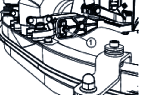
Adjust the inclination of the suction bar.
Tighten the screw.
The height adjustment affects the bending of the suction lips on contact with the floor.
Push the device a small distance forwards.
Compare the bending of the suction lips with the figure below.
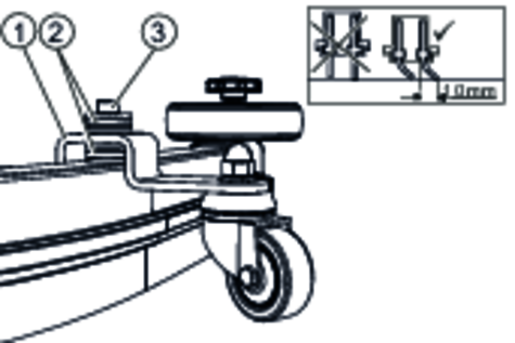
Unscrew the screw.
Insert a sufficient number of washers between the suction bar and spacer roller to create the correct bending of the suction lip.
Fit the remaining unused washers above the spacer roller.
Screw in and tighten the screw.
Repeat the entire procedure at the second spacer roller.
Push the device a small distance forwards.
Check the bending of the suction lips over the entire length.
Repeat the adjustment procedure if necessary.
Turn the key-operated switch to "1".
The display shows the following one after the other:
Period of time until the next after-sales Customer Service
Software version, control panel
Charging state of the battery and number of operating hours
The inclination and height of the suction bar can be adjusted to improve the vacuuming results (see chapter Adjusting the suction bar).
When the waste water tank is full, the float switch closes the suction opening and the suction turbine runs at a higher speed. In this case, raise the suction bar and drive to the location for emptying the waste water tank.
Turn the working speed rotary knob to the desired value.
The speed is shown on the display during the adjustment. The display is shown in percentage of the maximum speed.
Set the water volume at the regulating valve.
Press the suction bar lever downwards.
The suction bar lowers.
Vacuuming begins.
Press the cleaning head lever downwards, unlatch it and allow it to move upwards.
Pull the safety switch towards the push handle.
The cleaning head starts up and the device moves at the set speed.
Let go of the safety switch.
Lift the cleaning head lever up with your hand and latch it towards the right.
Let go of the safety switch.
Press the cleaning head lever down and latch it in place.
Continue moving a short distance.
The residual water is vacuumed up.
Lift the suction bar.
The suction continues to run for 10 seconds.
Turn the key-operated switch to "0".
Charge the battery if necessary.
Environmental pollution!
Environmental pollution due to improper disposal in waste water.
Observe the local waste water treatment regulations.
Remove the drain hose from the support and lower it over a suitable collecting device.
Press the dosing unit together or kink the hose.
Open the dosing unit cover.
Drain the waste water. Regulate the water volume by pressing or kinking.
Rinse the waste water tank with clear water.
Pull off the filling level indicator hose and swivel it down.
Unscrew the fresh water tank cap.
Allow the fresh water to drain away.
Fit the fresh water tank cap and screw into place.
Note: Take care to ensure that the hose connection in the fresh water tank cap is positioned at the lowest point in the tank after screwing the cap in place.
Driving on slopes
Risk of injury
Observe the maximum permissible inclination when driving the device on slopes for loading and unloading purposes (see chapter “Technical data”).
Drive slowly.
Failure to observe the weight
Risk of injury and damage
Be aware of the weight of the device during transport.
Only load the device with the assistance of another person or by using the drive.
Press the cleaning head lever down and latch it in place.
Raise the suction bar.
Turn the key-operated switch to "1".
Select the travel direction at the travel direction switch.
Pull the safety switch towards the push handle.
When transporting in vehicles, secure the device against slipping and tipping over according to the applicable guidelines.
First fit the strap under the waste water tank.
Risk of injury and damage!
The device may tip over on sloping surfaces.
Be aware of the weight of the device during storage.
Frost
Destruction of the device through freezing water
Drain all water from the device.
Store the device in a frost-free location.
This device may only be stored indoors.
Fully charge the batteries before storing them for a long period.
Fully charge the batteries at least every month during storage.
Risk of injury!
The device may start moving unexpectedly and cause injury.
Turn the key-operated switch to "0" and remove the key before performing any work on the device.
Pull out the charger mains plug.
Drain and dispose of the waste water and fresh water.
You can agree on regular safety inspections or close a maintenance contract with your dealer. Please seek advice on this.
Risk of damage!
Risk of damage to the device due to improper cleaning.
Do not spray the device with water and do not use aggressive detergents.
A detailed description of the individual maintenance work is provided in Chapter Maintenance work.
Drain the waste water.
Rinse the waste water tank with clear water.
Clean the exterior of the device using a damp cloth, wetted with a mild washing lye.
Check the fluff filter and clean if required.
Clean the coarse dirt filter.
Clean the coarse dirt filter.
Only BR variants: Remove and empty the coarse dirt receptacle.
Only BR variants: Clean the water distribution channel.
Clean the suction lips, check for wear and adjust the height or replace if necessary.
Check the disc brushes for wear and replace if necessary.
Charge the battery.
If the charging state of the battery is below 50%, charge the battery fully and without interruption.
If the charging state of the battery is above 50%, only recharge the battery if the entire operating duration will be required when next used.
When used regularly, charge the battery fully and without interruption at least once a week.
A detailed description of the individual maintenance work is provided in Chapter Maintenance work.
Drain the fresh water tank and flush out deposits.
Clean the fresh water filter.
Clean the float and fluff filter.
Check battery poles for oxidation, brush off if necessary. Make sure the connection cables are firmly in place.
Clean the seals between the waste water tank and the cover, check for leaks and replace if necessary.
Check the acid density of the cells if the batteries are not maintenance-free.
If the device is not used for a longer period of time, shut down the device when the batteries are fully charged. Fully charge the battery at least once a month.
Have the prescribed inspection performed by Customer Service.
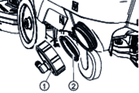
The suction lips must be turned over or replace when they have worn down to the wear mark.
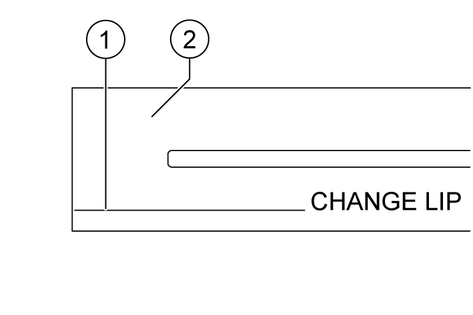
Remove the suction bar.
Unscrew the star handles.
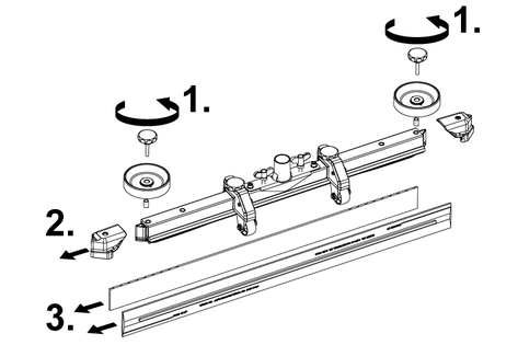
Pull off the plastic parts.
Pull off the suction lips.
Push in the turned over or new suction lips.
Push on the plastic parts.
Screw in and tighten the star handles.
Open the waste water tank cover.
Pull the coarse dirt filter upwards and off.
Rinse off the coarse dirt filter under running water.
Reinsert the coarse dirt filter into the waste water tank.
Drain the fresh water (see Chapter Draining fresh water).
Unscrew the fresh water tank lock.
Pull out the fresh water filter and rinse with clean water.
Insert the fresh water filter.
Fit the fresh water tank lock.
Note: Take care to ensure that the hose connection in the fresh water tank cap is positioned at the lowest point in the tank after screwing the cap in place.
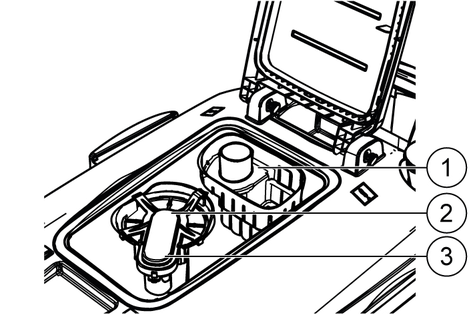
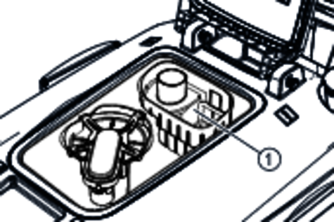
Open the waste water tank cover.
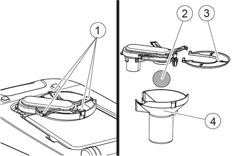
Release the latching hooks.
Pull the float housing downwards and off.
Remove the float from the float housing and clean it.
Remove the fluff filter and clean it.
Assemble all parts in the reverse order.
Raise the cleaning head.
Press the brush replacement pedal down, beyond the zone of resistance.
Pull the 1st disc brush sideways and out from underneath the cleaning head.
Hold the new disc brush under the cleaning head, then press upwards and latch it into position.
Repeat the procedure for the 2nd disc brush.
Raise the cleaning head.
Pull out the brush replacement handle.
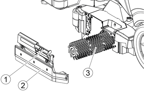
Remove the bearing cover including the squeegee blade.
Pull out the roller brush.
Fit the new roller brush and centre it on the driver.
Install the bearing cover with the squeegee blade.
Make sure the roller brush sits on the mounting mandrel and not underneath.
Pivot the brush replacement handle upwards and latch it into place.
Repeat the entire procedure at the other side.
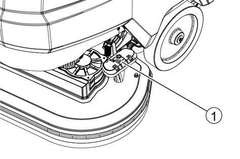
Press lock in the direction of the arrow and hold it there.
Pivot water distribution strip forward.
Pull out water distribution strip lengthways.
Clean the water distribution strip.
Fit water distribution strip back into the cleaning head and snap the lock into place.
Risk of injury!
The device may start moving unexpectedly and cause injury.
Turn the key-operated switch to "0" and remove the key before performing any work on the device.
Pull out the charger mains plug.
Drain and dispose of the waste water and fresh water.
Contact Customer Service in the case of malfunctions that cannot be corrected using this table.
Description | BD 70/75 part no. | BD 80/100 part no. | Description |
|---|---|---|---|
Disc brush, white (soft) | 4.905-011.0 | 4905-030.0 | For cleaning lightly soiled or sensitive floors |
Disc brush, natural colour (soft) | 4905-012.0 | 4905-031.0 | Made of natural fibres for cleaning and polishing |
Disc brush, red (medium, standard) | 4905-010.0 | 4.905-000.0 | For use in all common cleaning tasks |
Disc brush, black (hard) | 4905-013.0 | 4905-032.0 | For heavy soiling and basic cleaning, only for non-sensitive surfaces |
Pad drive board | 4762-590.0 | 4762-447.0 | For cleaning with pads, with quick-change coupling and centre-lock |
Pad, white | – | 6.371-331.0 | For polishing floors |
Pad, red (medium soft) | 6.369-003.0 | 6371-147.0 | For cleaning all floors |
Pad, green (medium hard) | 6.369-002.0 | 6371-148.0 | For cleaning heavily soiled floors and for basic cleaning |
Pad, black (hard) | 6.369-001.0 | 6371-169.0 | For stubborn soiling and for basic cleaning |
Pad, brown (SPP) | 2.639-290.0 | 2639-288.0 | For protective film application on hard and elastic surfaces |
Description | BR 75/75 part no. | BR 85/100 part no. | Description |
|---|---|---|---|
Roller brush, white | 6.907-771.0 | 6907-772.0 | For polishing and maintenance cleaning of sensitive floors. |
Roller brush, red | 4.035-605.0 | 4.035-606-0 | For maintenance cleaning of heavily soiled floors. |
Roller brush, orange | 6.907-730.0 | 6907-734.0 | For scrubbing structural floors (safety tiles, etc.). |
Roller brush, green | 6.907-732.0 | 6907-735.0 | For basic cleaning of heavily soiled floors and for coating removal (e.g. waxes, acrylates). |
Roller brush, black | 6.907-732.0 | 6907-736.0 | |
Pad roller shaft | 4762-627.0 | 4762-628.0 | For holding roller pads. |
| Microfiber roller | 4114-007.0 | 4114-008.0 | For maintenance cleaning of smooth floors. |
Description | BD 70/75 + BR 75/75 part no. | BD 80/100 + BR 85/100 part no. | Description |
|---|---|---|---|
Suction bar, 1030 mm, curved | 4.777-108.0 | – | Standard |
Suction bar, 1160 mm, curved | – | 4.777-102.0 | Standard |
Suction lip set, natural rubber | 4.037-144.0 | 4037-138.0 | Standard |
Suction lip set, PU (oil resistant) | 4.037-145.0 | 4037-140.0 | Oil-proof |
Suction lip set, Linatex | 4181-011.0 | 4181-006.0 | Tear-proof |
Device performance data | |
Nominal voltage | 24 V |
Battery capacity | 115 / 170 / 180 Ah (5 h) |
Mean power input | 1270 W |
Driving motor power | 250 W |
Suction turbine power | 500 W |
Brush drive power | 2 x 500 W |
Theoretical surface performance | 3500 m2/h |
Fresh water tank capacity | 75 l |
Waste water tank capacity | 75 l |
Water temperature max. | 50 °C |
Water pressure max. | 0,06 bar |
Aisle turning width | 1550 mm |
Max. working area slope | 2 % |
Vacuuming | |
Suction performance, air quantity | 24 l/s |
Suction performance, vacuum | 16 (160) kPa (mbar) |
Cleaning brushes | |
Working width | 700 mm |
Brush diameter | 356 mm |
Brush speed | 140 1/min |
Brush contact pressure | 300 / 500 N |
Dimensions and weights | |
Approved total weight | 325 kg |
Net weight (transport weight) | 251 kg |
Battery compartment dimensions | 575 x 380 mm |
Determined values in acc. with EN 60335-2-72 | |
Overall vibration value | <2,5 m/s2 |
Uncertainty K | 0,2 dB(A) |
Sound pressure level LpA | 65 dB(A) |
Uncertainty KpA | 2 dB(A) |
Sound power level LWA + K uncertaintyWA | 81 dB(A) |
Device performance data | |
Nominal voltage | 24 V |
Battery capacity | 170 / 180 Ah (5 h) |
Mean power input | 800 W |
Driving motor power | 250 W |
Suction turbine power | 500 W |
Brush drive power | 2 x 600 W |
Theoretical surface performance | 3.750 m2/h |
Fresh water tank capacity | 75 l |
Waste water tank capacity | 75 l |
Water temperature max. | 50 °C |
Water pressure max. | 0,06 bar |
Aisle turning width | 1550 mm |
Max. working area slope | 2 % |
Vacuuming | |
Suction performance, air quantity | 24 l/s |
Suction performance, vacuum | 16 (160) kPa (mbar) |
Cleaning brushes | |
Working width | 750 mm |
Brush length | 700 mm |
Brush diameter | 105 mm |
Brush speed | 1200 1/min |
Brush contact pressure | 400 N |
Dimensions and weights | |
Approved total weight | 330 kg |
Net weight (transport weight) | 225 kg |
Battery compartment dimensions | 575 x 380 mm |
Determined values in acc. with EN 60335-2-72 | |
Overall vibration value | <2,5 m/s2 |
Uncertainty K | 0,2 dB(A) |
Sound pressure level LpA | 65 dB(A) |
Uncertainty KpA | 2 dB(A) |
Sound power level LWA + K uncertaintyWA | 81 dB(A) |
Device performance data | |
Nominal voltage | 24 V |
Battery capacity | 170 / 180 / 240 / 285 Ah (5 h) |
Mean power input | 1320 W |
Driving motor power | 300 W |
Suction turbine power | 500 W |
Brush drive power | 2 x 500 W |
Theoretical surface performance | 4000 m2/h |
Fresh water tank capacity | 100 l |
Waste water tank capacity | 100 l |
Water temperature max. | 50 °C |
Water pressure max. | 0,06 bar |
Aisle turning width | 1650 mm |
Max. working area slope | 2 % |
Vacuuming | |
Suction performance, air quantity | 24 l/s |
Suction performance, vacuum | 16 (160) kPa (mbar) |
Cleaning brushes | |
Working width | 800 mm |
Brush diameter | 410 mm |
Brush speed | 140 1/min |
Brush contact pressure | 400 / 680 N |
Dimensions and weights | |
Approved total weight | 435 kg |
Net weight (transport weight) | 325 kg |
Battery compartment dimensions | 622 x 384 mm |
Determined values in acc. with EN 60335-2-72 | |
Overall vibration value | <2.5 m/s2 |
Uncertainty K | 0,2 dB(A) |
Sound pressure level LpA | 65 dB(A) |
Uncertainty KpA | 2 dB(A) |
Sound power level LWA + K uncertaintyWA | 81 dB(A) |
Device performance data | |
Nominal voltage | 24 V |
Battery capacity | 170 / 180 / 240 / 285 Ah (5 h) |
Mean power input | 1150 W |
Driving motor power | 300 W |
Suction turbine power | 500 W |
Brush drive power | 2 x 750 W |
Theoretical surface performance | 4.250 m2/h |
Fresh water tank capacity | 100 l |
Waste water tank capacity | 100 l |
Water temperature max. | 50 °C |
Water pressure max. | 0,06 bar |
Aisle turning width | 1650 mm |
Max. working area slope | 2 % |
Vacuuming | |
Suction performance, air quantity | 24 l/s |
Suction performance, vacuum | 16 (160) kPa (mbar) |
Cleaning brushes | |
Brush length | 800 mm |
Working width | 850 mm |
Brush diameter | 105 mm |
Brush speed | 1200 1/min |
Brush contact pressure | 490 N |
Dimensions and weights | |
Approved total weight | 440 kg |
Net weight (transport weight) | 340 kg |
Battery compartment dimensions | 622 x 384 mm |
Determined values in acc. with EN 60335-2-72 | |
Overall vibration value | <2.5 m/s2 |
Uncertainty K | 0,2 dB(A) |
Sound pressure level LpA | 65 dB(A) |
Uncertainty KpA | 2 dB(A) |
Sound power level LWA + K uncertaintyWA | 81 dB(A) |
EU Declaration of Conformity |
We hereby declare that the machine described below complies with the relevant basic safety and health requirements in the EU Directives, both in its basic design and construction as well as in the version placed in circulation by us. This declaration is invalidated by any changes made to the machine that are not approved by us.
Product: Floor cleaner
Type: 1.127-xxx, 1.515-xxx
Currently applicable EU Directives2006/42/EC (+2009/127/EC)
2014/30/EU
2014/53/EU (TCU)
Harmonised standards usedEN 60335-1
EN 60335-2-72
EN 55012: 2007 + A1: 2009
EN 61000-6-2: 2005
EN 62233: 2008
TCUEN 301 511 V12.5.1
EN 300 440 V2.1.1
EN 300 328 V2.2.2
EN 300 330 V2.1.1
National standards used-
The signatories act on behalf of and with the authority of the company management.

Documentation supervisor:
S. Reiser
Alfred Kärcher SE & Co. KG
Alfred-Kärcher-Str. 28 - 40
71364 Winnenden (Germany)
Ph.: +49 7195 14-0
Fax: +49 7195 14-2212
Winnenden, 2021/02/01
Declaration of Conformity (UK) |
We hereby declare that the product described below complies with the relevant provisions of the following UK Regulations, both in its basic design and construction as well as in the version put into circulation by us. This declaration shall cease to be valid if the product is modified without our prior approval.
Product: Floor cleaner
Type: 1.127-xxx, 1.515-xxx
Currently applicable UK RegulationsS.I. 2008/1597 (as amended)
S.I. 2016/1091 (as amended)
S.I. 2017/1206 (as amended) (TCU)
Designated standards usedEN 60335-1
EN 60335-2-72
EN 55012: 2007 + A1: 2009
EN 61000-6-2: 2005
EN 62233: 2008
TCUEN 301 511 V12.5.1
EN 300 440 V2.1.1
EN 300 328 V2.2.2
EN 300 330 V2.1.1
National standards used-
The signatories act on behalf of and with the authority of the company management.
Documentation supervisor:
S. Reiser
Alfred Kärcher SE & Co. KG
Alfred-Kärcher-Str. 28 - 40
71364 Winnenden (Germany)
Ph.: +49 7195 14-0
Fax: +49 7195 14-2212
Winnenden, 2021/02/01

2-2-SC-A4-GS-aw19869