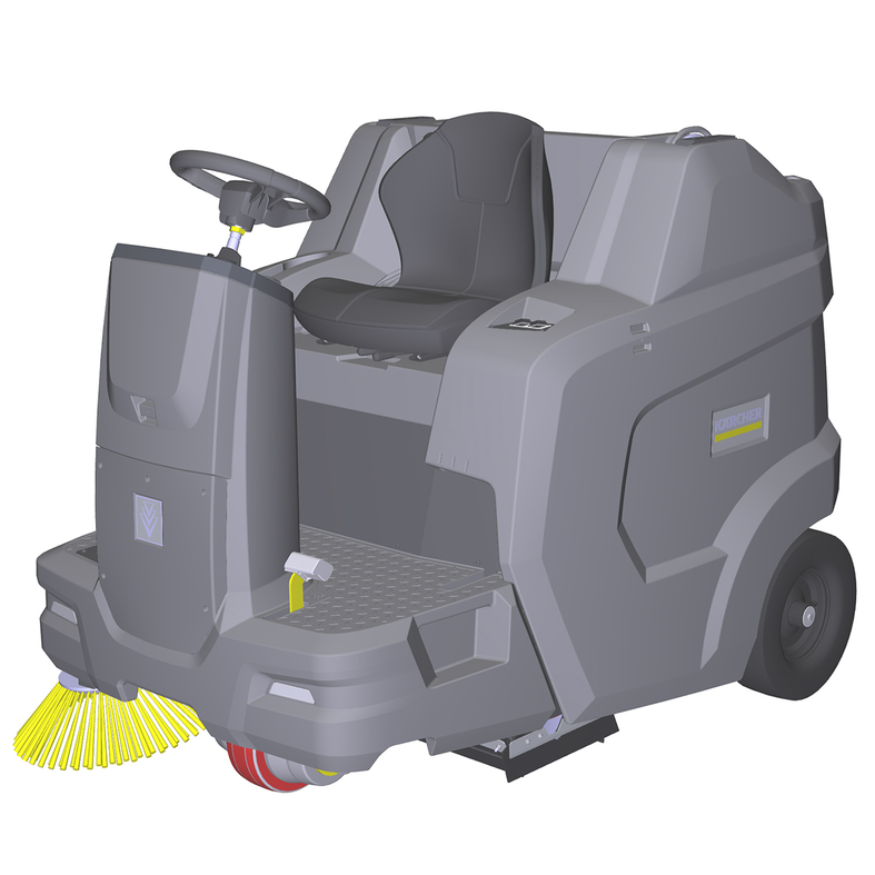
KM 100/120 R BpKM 100/120 R Bp Pack
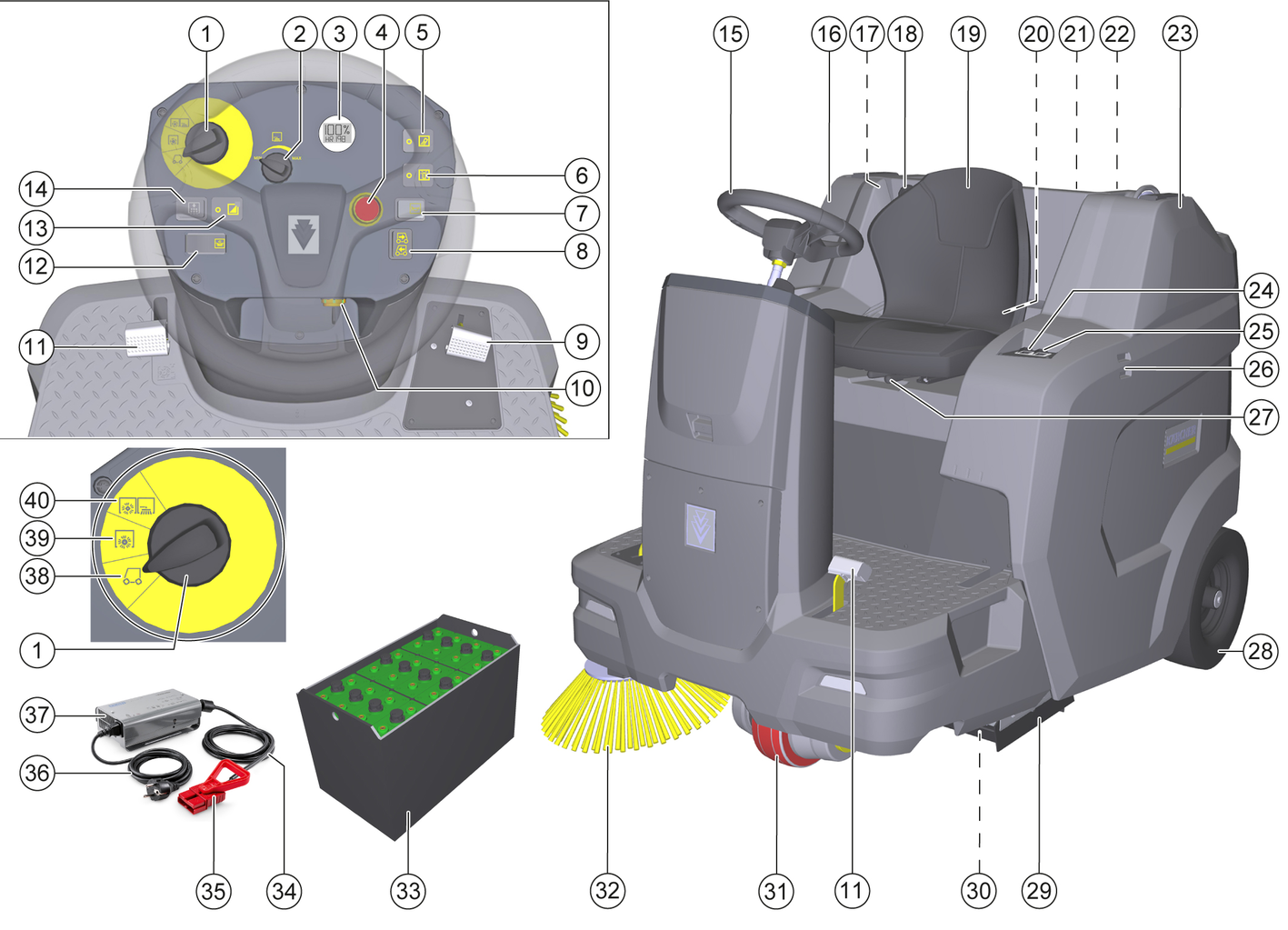
59800500 (02/23)
59800500 (02/23)
 Read and observe these original instructions and the operating instructions accompanying the battery and charger before using the machine for the first time. Keep the operating instructions for future reference or for future owners.
Indication of an imminent threat of danger that will lead to severe injuries or even death.
Indication of a potentially dangerous situation that may lead to severe injuries or even death.
Indication of a potentially dangerous situation that may lead to minor injuries.
Indication of a potentially dangerous situation that may lead to damage to property.
Never leave the device unattended unless the device is secured against unintentional movement. Always apply the parking brake before leaving the device.
Only use the device for its proper use. Take into account the local conditions and beware of third parties, in particular children, when working with the device.
Check that the machine, the working devices and the safety devices are in good working order, check the functionality and operational safety before using the machine. If the condition is not perfect or safe to operate, do not use the machine.
Adhere to the respective safety regulations in hazard zones (e.g. service stations). Never operate the device in explosive spaces.
The device is not intended for use by persons with restricted physical, sensory or mental abilities or those lacking in experience and / or lacking in knowledge.
Only people who have been instructed on how to use the device, or have proven their ability to operate it, and have been explicitly instructed to use it, must use the device.
Wear tight-fitting clothing and solid footwear when operating or maintaining the machine.
Do not use the machine in areas in which there is a possibility of being struck by falling objects.
Children must be supervised to prevent them from playing with the appliance.
Children and minors must not use the device.
Do not look directly into the light source on devices equipped with Blue Spot lighting.
The person operating the machine is responsible for accidents with other people and their property.
Check the immediate area before you start up, e.g. for children and animals. Make sure you always have a good view.
Remove the key from the key switch or remove the Kärcher Intelligent Key (KIK) from the holder on the machine to prevent unauthorised use of the machine.
The list on the risk of overturning is not necessarily comprehensive.
Danger of tipping over on excessively steep slopes and gradients! When driving on uphill and downhill slopes, observe the maximum permissible values in the Technical data chapter.
Danger of tipping over if sideways inclination is too great! On uphill and downhill slopes, when driving across the fall line, observe the maximum permissible values in the Technical data chapter.
Danger of tipping on unstable surfaces! Only drive the machine on stable ground.
Danger of accidents due to inappropriate speed. Drive slowly in curves.
Risk of explosion! Only charge batteries with a suitable charger
Highly explosive gas is produced when charging batteries in confined spaces. Only charge batteries in well ventilated spaces.
Keep naked flames away from the battery or the battery charging room, and do not generate sparks or smoke in the vicinity of a battery of a battery charging room.
Risk of explosion and short circuits. Do not place tools or similar items on the battery.
Risk of injury from battery acid. Adhere to the respective safety regulations.
Adhere to the operating instruction of the manufacturer of the battery and charger. Adhere to the recommendations of the legislature regarding the handling of batteries.
Never leave batteries in a discharged state. Charge batteries again as soon as possible.
Keep batteries clean and dry in order to avoid leakage currents. Protect batteries from contamination, e.g. from metal dust.
Dispose of used batteries in an environmentally friendly manner in accordance with the EC Directive 91/157/EEC or the respective national regulations.
In order to prevent accidents or injuries, you must take into account the weight of the device, see chapter Technical data in the operating instructions.
Shut the motor down prior to transportation. Secure the device, taking into account its weight. See chapter Technical data in the operating instructions.
Disconnect the battery before working on the electrical system.
Before cleaning, maintenance, replacing parts and resetting to another function, you must switch off the device and remove the ignition key.
Repairs may only be carried out by approved customer service sites or staff qualified in this area who are familiar with all relevant safety instructions.
Adhere to the safety inspection requirements for mobile devices for industrial use in accordance with the locally applicable regulations (e.g. in Germany: VDE 0701).
Short-circuits or other damage. Do not clean the device with a hose or high-pressure water jet.
Always wear suitable gloves when working on the device.
Safety devices protect the user and may not taken out of operation or functionally circumvented.
Adhere to the safety instructions in the chapters!
The left and right panels contain safety switch-off circuits that switch off the machine if the left or right panel is not closed correctly.
The driving and cleaning functions are only active when the left and right panels are closed correctly.
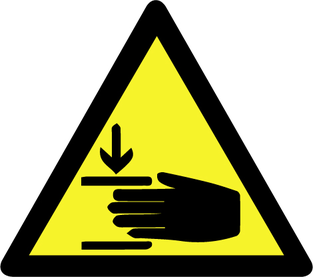
To prevent persons from reaching into the emptying mechanism and the swivel range of the waste container, lifting, lowering and emptying the waste container is only possible with two-handed operation.
It is not permitted to stand under the waste container unless it is fully raised and secured against lowering with the supplied, correctly fitted safety brace.
The seat contact switch means that the driving and cleaning functions are only active when a person is sitting in the driver's seat.
In the case of danger, all driving and cleaning functions can be switched off immediately by pressing the emergency stop switch.
To unlock, turn the red button of the emergency stop switch.
 | DANGERRisk of fire Do not sweep up burning or glowing objects such as cigarettes, matches or similar objects. |
 | DANGERRisk of accident from tipping Only use high dumping on level ground. |
 | WARNINGRisk of injury Risk of being squeezed or hurt at the belts, side-brushes, waste container, cover. |
 | WARNINGRisk of injury Cut and crush injuries from moving vehicle parts inside. Do not reach into openings in the device. |
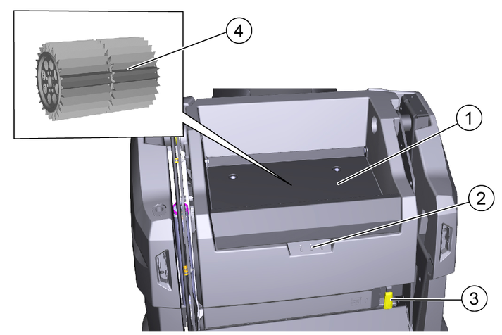
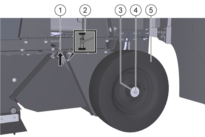
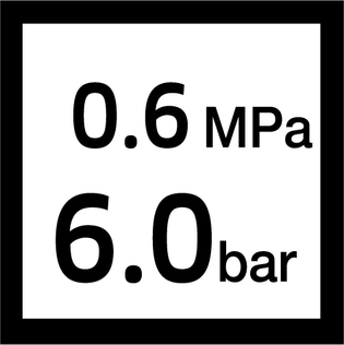 | Tyre pressure |
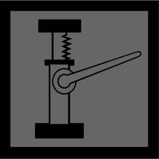 | Jacking point |
 | Fastening point |
 | Max. load of the storage area 20 kg |
 | Max. load 150 kg |
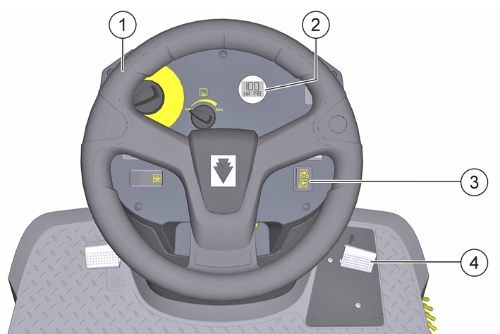
 | Coarse dirt flap pedal |
 | Wet sweeping flap |
 | Releasing/fastening the dust filter |
Use the battery-operated sweeper for cleaning indoor and outdoor floor areas.
The sweeper is designed for commercial use.
Use the sweeper for the following intended areas of application:
Parking spaces
Footpaths
Production systems
Logistics areas
Hotels
Retail trade
Storage areas
Only use the sweeper in accordance with the information in these operating instructions. Any other use is considered as improper use. The manufacturer assumes no liability for any resultant damage. The user is solely responsible for the risk.
No modifications must be made to the sweeper.
Only the areas approved by the company or the company's representatives must be driven on and cleaned.
Never sweep or suction up explosive liquids, gases, non-diluted acids or solvents (e.g. petrol, paint thinner, heating oil) because they form explosive vapours or mixtures in conjunction with the suction air.
Never sweep or suction up acetone, non-diluted acids or solvents, as they will corrode and damage the materials used on the device.
Never sweep or suction up reactive metal dusts (e.g. aluminium, magnesium, zinc). They form explosive gases in conjunction with highly alkaline or acidic cleaning agents.
Do not sweep or suction up burning or smouldering objects. There is a risk of fire.
Do not sweep up any harmful substances.
Standing in hazard zones is prohibited. Operation in explosive spaces is prohibited.
Carrying passengers is prohibited.
This device must not be used to push/pull or transport objects.
Asphalt
Industrial floor
Screed
Concrete
Paving stones
 The packing materials can be recycled. Please dispose of packaging in accordance with the environmental regulations.
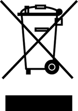 Electrical and electronic devices contain valuable, recyclable materials and often components such as batteries, rechargeable batteries or oil, which - if handled or disposed of incorrectly - can pose a potential danger to human health and the environment. However, these components are required for the correct operation of the device. Devices marked by this symbol are not allowed to be disposed of together with the household rubbish.
Current information on content materials can be found at: www.kaercher.de/REACH
Vehicles that are no longer fit for service contain valuable recyclable materials. We recommend you cooperate with a waste management company with regard to the disposal of your vehicle.
Only use original accessories and original spare parts. They ensure that the appliance will run fault-free and safely.
Information on accessories and spare parts can be found at www.kaercher.com.
Please report any defects or shipping damage identified on the vehicle when it is handed over directly to your dealer or department store.
The sweeper operates using the direct-throw principle.
The rotating side brushes clean corners and edges of the sweeping surface and convey the waste into the path of the roller brush.
The rotating roller brush conveys the waste directly into the waste container.
The dust swirled up in the waste container is separated by a dust filter, and the suction fan sucks away the filtered air.
Cleaning of the dust filter occurs automatically during operation.
* For a description of this, see chapter Program selection switch
** For a description of this, see chapter Display
*** only KM 100/120 R Bp pack
Not shown are special options that are already fitted when ordered ex works or can be retrofitted by the service department, see chapter Accessories/wear parts.
The functions are only active when the key-operated switch is in position "I".
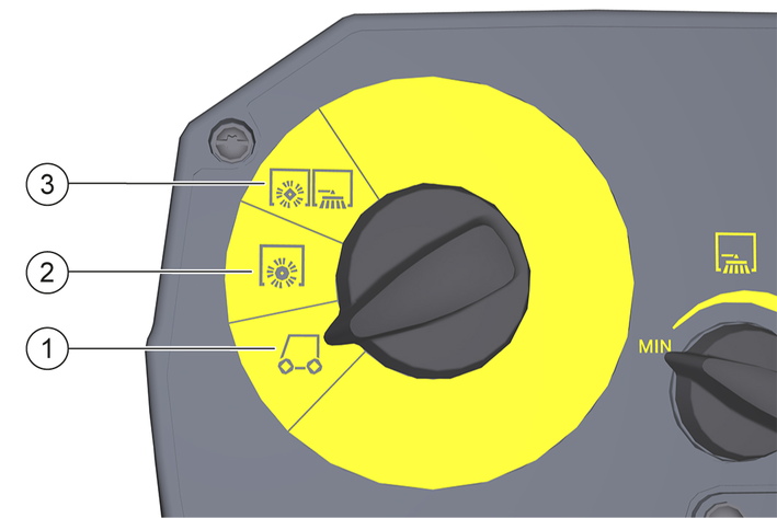
The machine can be driven to the operating location.
The roller brush and side brushes are raised and switched off.
The roller brush is lowered and switched on.
The roller brush and right and left (optional) side brushes are lowered and switched on.
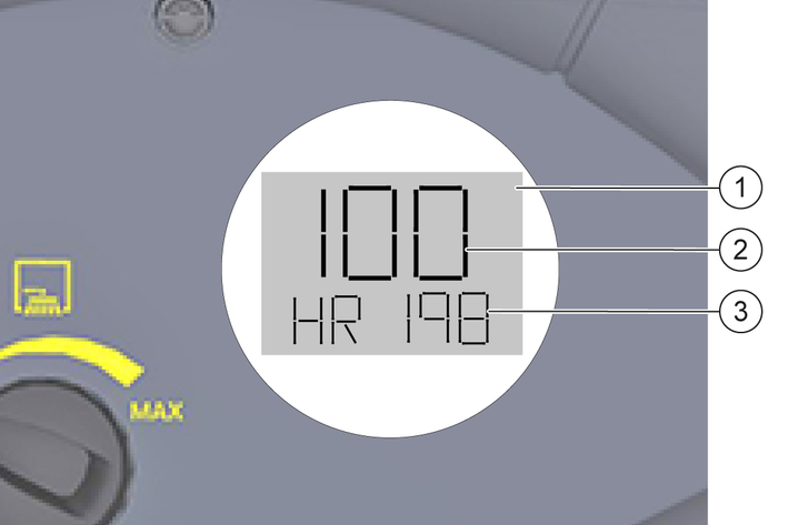
If the key switch is in position "I", the display shows the following:
the battery charge status in %
the operating hours counter
If the display shows one of the following messages, release the corresponding button or the accelerator pedal:
W 1 (The unlock waste container button is pressed)
W 2 (The raise waste container button is pressed)
W 3 (The lower waste container button is pressed)
W 4 (The accelerator pedal is depressed)
If the message is still displayed, contact the service department.
If the following message appears on the display, contact the service department:
E ...,
If the battery charge status is < 20%, a warning tone sounds every 2 min. Charge the battery as soon as possible, see chapter Charging the battery.
If the battery charge status is < 10%, the roller brush and side brushes are switched off. Charge the battery immediately, see chapter Charging the battery.
Malfunction due to open panels
Only open the panels when the key switch is on <0> and the key has been removed.
Opening during operation is prohibited.
Open the left-hand cladding for the following operations:
Remove/check /install the roller brush, see chapter Removing/checking/installing the roller brush
Clean the inside of the machine, see chapter Cleaning the interior of the machine
Remove/install the left rear wheel, see chapter Removing/installing the rear wheel
Replace the fuse, see chapter Removing/installing the fuse
Open the right-hand cladding for the following operations:
Disconnect/connect the power supply, see chapter Disconnecting/connecting the power supply
Charge the battery, see chapter Charging the battery
Clean the inside of the machine, see chapter Cleaning the interior of the machine
Remove/install the right rear wheel, see chapter Removing/installing the rear wheel
Switch off the machine, see chapter Switching off the machine.
Open the left/right cladding:
Grasp the recessed grip at the front of the left/right-hand cladding, lift slightly and swing the left/right-hand cladding to the side.
Shown on the left-hand cladding of a KM 100/120 R G
Close the left/right cladding:
Swing back the left/right-hand cladding until it audibly engages on the machine.
The maximum permissible load on the storage compartments is 20 kg.
Ensure that the load is securely fastened.
Risk of injury and damage when loading the machine!
When loading the machine, there is a risk of injury from the machine rolling away, tipping over and falling.
When loading, take into account the weight and dimensions of the machine and use a suitable ramp.
When loading, secure the machine against rolling away, tipping over and falling.
Do not use a forklift for loading.
Load the machine only on level, horizontal ground.
On uphill and downhill slopes, move the machine only with the machine's own travel drive, never by pushing.
Dimensions, weights and maximum climbing ability see chapter Technical data.
Figure: Installing the ramp
Cut the plastic packing tapes and remove the packing films.
Make the machine ready to drive:
KM 100/120 R Bp: Install and connect a battery, see chapter Installing/connecting/removing the battery.
KM 100/120 R Bp pack: Connect the power supply, see chapter Disconnecting/connecting the power supply.
If necessary, charge the battery, see chapter Charging the battery.
Remove the tensioning strap fastening at the eyelet points.
Unscrew the three boards shown and the squared timber on the pallet.
Position the boards on the edge of the pallet; align the boards so that they are flush with the wheels of the machine. Screw the boards tightly to the pallet.
Place the squared timber under the boards as a support.
Remove the wooden blocks on the wheels.
Carefully drive the machine off the pallet via the ramp created, see chapter Driving the machine.
Risk of injury and damage when releasing or activating the parking brake due to the machine rolling away!
When releasing or activating the parking brake, the machine can roll away and roll over or jam/crush people, animals or body parts.
Before releasing or activating the parking brake, secure the machine against rolling away with chocks.
Only release the parking brake when the machine is standing on level and horizontal ground.
Only push the machine on level ground, never on uphill and downhill slopes.
Only move the machine on uphill and downhill slopes using the machine's own drive.
Immediately after each push, secure the machine again with chocks to prevent it from rolling away.
When pushing, take into account the weight and dimensions of the machine, enlist help if necessary.
Before pushing the machine, read the chapter Releasing/activating the parking brake read!
Only use the batteries and chargers recommended by the manufacturer
Only replace batteries with batteries of the same type.
Before disposing of the vehicle, remove the battery and dispose of it in accordance with national or local regulations.
Observe the following warnings when handling the batteries:
 | Observe notes in the instructions for the battery, on the battery and in these operating instructions. |
 | Wear eye protection. |
 | Keep acids and batteries away from children. |
 | Risk of explosion |
 | Fire, sparks, open flames and smoking are prohibited. |
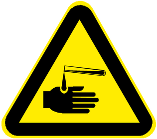 | Risk of acid burns |
 | First aid |
 | Warning |
| Disposal |
| Do not throw batteries in the bin. |
Risk of fire and explosion
Do not place tools or other objects on the battery.
Naked flames and smoking must be strictly avoided.
Ensure the room is well ventilated when charging batteries.
Only use batteries and chargers approved by Kärcher (original spare parts).
Environmental risk due to improper disposal of batteries
Ensure that defect or used batteries are disposed of safely (contact a waste management company or Kärcher Service).
When used normally, and when observing the instructions, lead-acid batteries do not pose any risk.
However, keep in mind that lead-acid batteries contain sulphuric acid which can cause serious chemical burns and corrosion.
If there is spillage or, if the battery is leaking, acid is escaping, lay down a binding agent such as sand. Do not let it reach the sewer system, soil or a body of water.
Neutralise the acid with lime/baking soda and dispose of it according to local regulations.
Contact a waste management company to dispose of faulty batteries.
Rinse out your eyes or rinse off your skin with copious amounts of fresh water if acid splashes into your eyes or onto your skin.
Then consult a doctor immediately.
Wash any contaminated clothing with water.
Change clothes.
Risk of injury and damage due to short-circuit!
When working in the area of the battery, there is a risk of injury and damage due to short-circuits.
Do not place any tools or other objects on the battery.
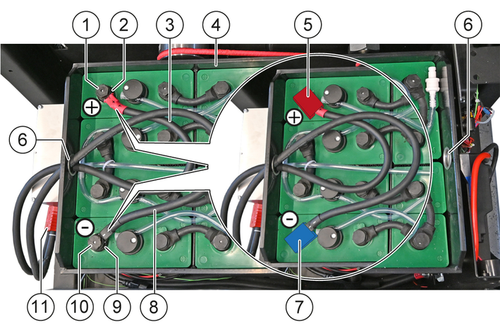
Installation: Always fit the positive cable onto the plus terminal first and then the minus cable to the minus terminal.
Removal: Always remove the minus cable at the minus terminal first and then the positive cable at the plus terminal.
Take care to ensure the correct assignment: Positive cable to plus terminal and minus cable to minus terminal.
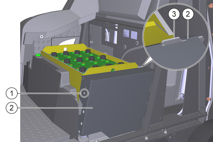
The battery and charger are part of the scope of delivery for the KM 100/120 R Bp Pack.
Switch off the machine, see chapter Switching off the machine.
Installation:
Open the left and right panels, see chapter Open/close the left/right cladding.
Remove the positive and negative cables with the battery-side battery plug from the battery holder of the machine.
Attach a suitable hoist to the left and right lifting eyes of the battery.
For the battery weight, see chapter Technical data.
Carefully place the battery into the battery holder of the machine using the hoist.
The unused positive and negative terminals must be on the right-hand side of the machine.
Remove the hoist at the left and right lifting eyes.
Connection:
First connect the positive cable to the positive terminal of the battery and fit the positive terminal cover, see chapter Installing/removing the positive/negative cable on the battery.
Connect the negative cable to the negative terminal of the battery and fit the negative terminal cover, see chapter Installing/removing the positive/negative cable on the battery.
Connect the power supply, see chapter Disconnecting/connecting the power supply.
Turn the key in the key-operated switch to position "I".
Read the battery charge status on the display and charge the battery if necessary, see chapter Charging the battery.
Removing:
Removal is performed in the reverse sequence.
Risk of injury and damage due to short-circuit!
When working in the area of the battery, there is a risk of injury and damage due to short-circuits.
Do not place any tools or other objects on the battery.
Installation: Always fit the positive cable onto the plus terminal first and then the minus cable to the minus terminal.
Removal: Always remove the minus cable at the minus terminal first and then the positive cable at the plus terminal.
Take care to ensure the correct assignment: Positive cable to plus terminal and minus cable to minus terminal.
Installing:
Disconnect the power supply, see chapter Disconnecting/connecting the power supply.
Route the positive cable through the right-hand lifting eye of the battery to the positive terminal as shown.

Remove the transport cover on the positive terminal and store it.
Screw the positive cable to the positive terminal with the positive terminal screw.
Tightening torque: 25 Nm.
Fit the positive terminal cover on the positive terminal.
Route the negative cable through the right-hand lifting eye of the battery to the negative terminal as shown.
Remove the cover on the negative terminal and store it.
Screw the negative cable to the negative terminal with the negative terminal screw.
Tightening torque: 25 Nm.
Fit the negative terminal cover on the negative terminal.
Connect the power supply, see chapter Disconnecting/connecting the power supply.
Removing:
Removal is performed in the reverse sequence.
Switch off the machine, see chapter Switching off the machine.
Open the right-hand cladding, see chapter Open/close the left/right cladding.
Disconnecting:
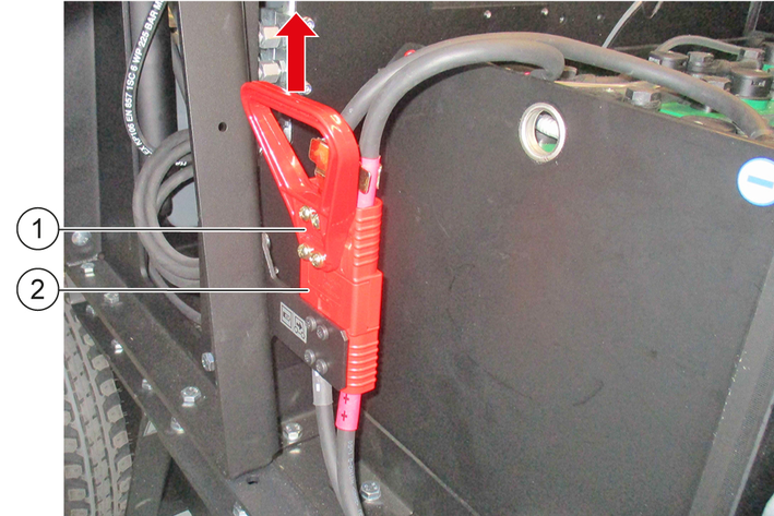
Disconnect the machine-side battery connector from the battery-side battery connector.
The machine is de-energised.
Connecting:
Plug the machine-side battery connector into the battery-side battery connector until the two connector housings are against each other.
The power supply to the machine is established.
Close the right-hand cladding, see chapter Open/close the left/right cladding.
Risk of injury and damage due to short-circuit!
When working in the area of the battery, there is a risk of injury and damage due to short-circuits.
Do not place any tools or other objects on the battery.
Installation: Always fit the positive cable onto the plus terminal first and then the minus cable to the minus terminal.
Removal: Always remove the minus cable at the minus terminal first and then the positive cable at the plus terminal.
Take care to ensure the correct assignment: Positive cable to plus terminal and minus cable to minus terminal.
Move the machine to a dry, well-ventilated interior.
Switch off the machine, see chapter Switching off the machine.
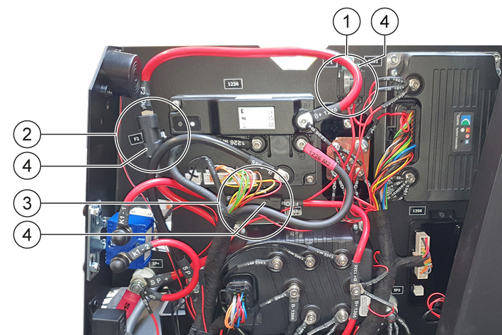
Connecting the charger:
Disconnect the power supply, see chapter Disconnecting/connecting the power supply.
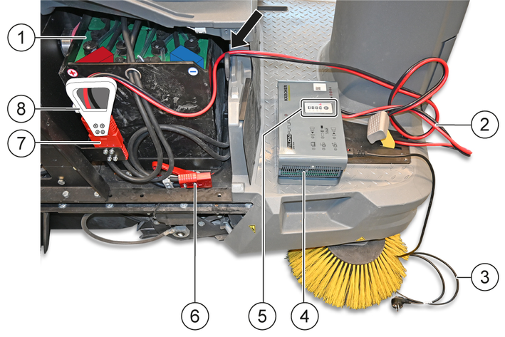
Battery
Charging cable
Mains cable
Portable charger
LED display
Machine-side battery connector
Battery-side battery connector
Charging plug
Place the portable charger on the step surface of the machine.
The feet must point downwards.
Do not place the portable charger on the battery!
Do not cover the portable charger with objects and do not place any objects on it!
Route the charging cable through the cable inlet (arrow) on the separating wall to the battery-side battery connector.
Plug the charging plug into the battery-side battery connector until the two connector housings are against each other.
Place the machine-side battery connector and the charging cable in such a way that they are not damaged when closing the right-hand cladding!
Plug the mains cable into the portable charger.
Plug the mains cable into an earthed socket outlet.
The charging process starts and ends automatically.
The LED display shows the current status:
yellow = battery charging
flashes green = battery is > 80% charged
lights up green = battery is fully charged
red = there is a fault
For charging time, see chapter Technical data.
Towards the end of the charging time, check the electrolyte level according to the battery manufacturer's operating instructions and correct it if necessary.
Disconnecting the charger:
After charging, disconnect the charger from the machine in reverse order.
Check the battery charge status, charge the battery if necessary, see chapter Charging the battery.
Check the switch-off function of the left and right cover, see chapter Left and right panels, if necessary, inform the service department.
Check the switch-off function of the seat contact switch, see chapter Seat contact switch, inform the service department if necessary.
Check the tyre inflation pressure of the rear wheels and correct if necessary. For the tyre inflation pressure, see chapter Technical data.
Check the roller brushes and side brushes for foreign bodies and long, flexible objects such as ribbons or strings, remove foreign bodies and flexible objects if necessary.
Turn the key switch to the "O" position, and check the accelerator pedal for ease of movement when the machine is at a standstill, inform the service department if necessary.
Danger of accident
Only adjust the driver’s seat when the device is standing.
Pull the seat adjustment lever to the right and move the driver's seat to the desired position.
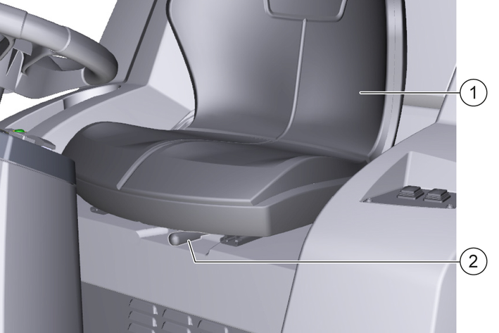
Release the seat adjustment lever.
Move the driver's seat back and forth to check that it is properly latched in place.
Risk of injury and damage when releasing or activating the parking brake due to the machine rolling away!
When releasing or activating the parking brake, the machine can roll away and roll over or jam/crush people, animals or body parts.
Before releasing or activating the parking brake, secure the machine against rolling away with chocks.
Only release the parking brake when the machine is standing on level and horizontal ground.
Only push the machine on level ground, never on uphill and downhill slopes.
Only move the machine on uphill and downhill slopes using the machine's own drive.
Immediately after each push, secure the machine again with chocks to prevent it from rolling away.
When pushing, take into account the weight and dimensions of the machine, enlist help if necessary.
The parking brake is automatically activated when the machine is at a standstill and automatically released when the machine is started.
The parking brake acts on the front wheel.
To be able to push the machine, the parking brake must be released mechanically.
For dimensions and weights, see chapter Technical data.
Release the parking brake:
Park the machine on level, horizontal ground and switch it off, see chapter Switching off the machine.
Secure the machine against rolling away with wheel chocks.
Lift off the lever on the parking brake and insert an object (e.g. wedge) between the lever and the parking brake.
The parking brake is released.
Remove the chocks and push the machine.
Activate the parking brake:
Use chocks to secure the machine against rolling away.
Remove the inserted object (e.g. wedge) between the lever and the wheel hub motor.
The parking brake is activated.Remove the chocks.
To start the machine, the left and right panels must be closed and the driver must be seated in the driver's seat.
Sit in the driver's seat.
The seat contact switch is actuated.
Insert the key into the key-operated switch and turn it to position "I".
Turn the program selection switch to the desired position, for functions see chapter Program selection switch.
Risk of injury due to abrupt stopping!
The machine comes to an abrupt stop as soon as the driver's seat is not occupied.
Do not stand up from the driver's seat while driving.
Risk of accidents when reversing!
There is an increased risk of accidents when reversing.
Before reversing, make sure that you do not endanger anyone, pay particular attention to children. Have a person brief you if necessary.
When reversing, observe the entire surroundings.
Risk of accident when driving with raised waste container!
When driving with the waste container raised, there is an increased risk of accidents due to a change in the machine's centre of gravity.
Do not drive with the waste container raised.
Risk of damage to the drive!
Jerky operation of the accelerator pedal can damage the drive.
Always operate the accelerator pedal slowly and carefully.
Bring the machine to a standstill before changing from forward to reverse or vice versa.
The lever on the parking brake in the front wheel must be in the driving position, see chapter Releasing/activating the parking brake.
Start the machine, see chapter Starting the machine.
Check the battery charge status on the display, charge the battery if necessary, see chapter Charging the battery.
Press the travel direction switch to the "Forward travel" or "Reverse travel" position.
Press the accelerator pedal carefully and adjust the travel speed steplessly.
Do not jerk the accelerator pedal.
Steer the travel direction using the steering wheel.
Release the accelerator pedal to reduce speed.
Adjust the travel speed to the circumstances and drive forwards for optimum cleaning results.
Sweeping is only possible with the waste container retracted.
The container flap is automatically closed when the program selection switch is set to "Drive".
The waste container flap is automatically opened and sweeping is possible when the program selection switch is set to "Sweeping with roller brush" or "Sweeping with roller brush and side brush".
The dust filter is automatically cleaned at regular intervals. In case of very high dust accumulation between the intervals, press the dust filter cleaning button to trigger additional dust filter cleaning.
Empty the waste container at regular intervals, see chapter Emptying the waste container. Do not exceed the maximum load of the waste container, see chapter Technical data.
If mainly high-density waste (grit, sand, etc.) are collected, empty the waste container earlier accordingly.
Fixed obstacles up to 6 cm high can be driven over slowly and carefully.
Drive over fixed obstacles of more than 6 cm in height with a suitable ramp.
Risk of injury due to abrupt stopping!
The machine comes to an abrupt stop as soon as the driver's seat is not occupied.
Do not stand up from the driver's seat while driving.
Risk of injury from ejected waste!
Ejected waste (e.g. stones) can injure bystanders or animals when the coarse dirt flap is open.
Do not open the coarse dirt flap when people or animals are near the machine.
Risk of damage by sweeping up tapes and cords!
If long, flexible objects such as e.g. tapes or cords are swept up, they can damage the sweeping mechanism.
Do not drive the machine or side brush over long, flexible objects such as e.g. tapes or cords and do not sweep up such objects.
For sweeping, select the program "Sweeping with roller brush", see chapter Program selection switch.
The roller brush is switched on and lowered.
For cleaning close to the edge, select the program "Sweeping with roller brush and side brushes", see chapter Program selection switch.
The roller brush and side brushes are switched on and lowered.
For wet or damp surfaces, open the wet sweeping flap.
The suction power is reduced and excessive moisture penetration of the dust filter is prevented
To sweep up larger objects up to approx. 50 mm, briefly press the coarse dirt flap pedal.
Risk of injury due to falling objects!
When lifting and lowering the waste container, there is a risk of injury from objects falling from the storage surface.
Before lifting the waste container, remove all objects that are not securely fastened from the storage surface.
Risk of injury due to tipping of the machine when emptying the waste container!
Empty the waste container only on firm, level ground.
Maintain a safety distance when emptying on stockpiles and ramps.
Risk of injury when standing in the swivel range of the waste container!
Make sure that no persons or animals are in the swivel range of the waste container during the emptying process.
Risk of injury due to crushing or shearing off of body parts when reaching into the mechanics of the waste container!
Do not reach into the movement area or the components of the emptying mechanism of the waste container.
Risk of injury if the waste container falls!
The raised waste container can fall abruptly and cause serious injuries due to crushing and trapping.
Do not walk underneath the waste container if it is unsecured.
Secure the raised waste container properly with the supplied safety brace before walking underneath the waste container.
With the high emptying of the machine, the waste container can be emptied into e.g. a waste container (for maximum unloading height see chapter Technical data).
Raising:
Remove all objects that are not securely fastened from the storage area.
Set the program selection switch to "Drive", see chapter Program selection switch.
The waste container can only be raised in this position.
Position the machine in front of the unloading point.
Ensure sufficient clearance behind and above the waste container.
Wait at least 1 minute until the dust has settled in the waste container.
Emptying:
Press and hold the "Unlock waste container" button.
For safety reasons, the waste container can only be emptied in two-handed operation. Hold the "Unlock waste container" button pressed during the entire emptying process.
Press and hold the "Raise/lower waste container" button in the "Raise" position.
The waste container is raised.
Raise the waste container completely to empty into a high container.
Then slowly drive up to the container.
To empty onto the ground or into low containers, raise the waste container at least 75 cm.
It is not possible to open the container flap at a lower height.
Release the "Raise/lower waste container" button.
Press the "Open/close container flap" button to the "Open" position.
The container flap is opened and the waste container emptied.
Press the "Open/close container flap" button to the "Close" position.
The container flap is closed.
Lowering:
Move the machine approx. 2 m away from the unloading point.
Ensure sufficient clearance behind and under the waste container.
Press the "Raise/lower waste container" button to the "Lower" position and lower the waste container completely.
Release the "Unlock waste container" button and the "Raise/lower waste container" button.
Put the removed objects back on the storage surface.
Press the emergency stop switch if a hazardous situation requires the machine and all travel and cleaning functions to be switched off immediately, see chapter Emergency stop switch.
Do not use the emergency stop switch to switch off the machine in normal operation, but proceed as follows:
Park the machine on a level surface.
The parking brake is automatically activated when the machine is at a standstill.
Empty the waste container every day before the machine is switched off for the last time, see chapter Emptying the waste container.
Charge the battery every day after the last time the machine was switched off, see chapter Charging the battery.
Turn the program selector switch to the "Drive" position.
Turn the key in the key switch to position "O" and remove it.
The dust filter is cleaned automatically, then the machine switches off completely.
Risk of injury and damage when loading the machine!
When loading the machine, there is a risk of injury from the machine rolling away, tipping over and falling.
When loading, take into account the weight and dimensions of the machine and use a suitable ramp.
When loading, secure the machine against rolling away, tipping over and falling.
Do not use a forklift for loading.
Load the machine only on level, horizontal ground.
On uphill and downhill slopes, move the machine only with the machine's own travel drive, never by pushing.
Risk of injury or damage due to non-observance of the weight!
Risk of injury and damage due to non-observance of the weight during transport and storage of the machine.
Be aware of the weight of the machine during transport and storage.
Secure the machine against slipping and tipping during transport in accordance with the applicable regulations.
Load the machine, see chapter Unload the machine.
Switch off the machine, see chapter Switching off the machine.
Disconnect the power supply, see chapter Disconnecting/connecting the power supply.
Secure the machine on the wheels with chocks to prevent it from rolling away.
Tie down the machine with suitable tension belts or ropes at the marked fixing points.
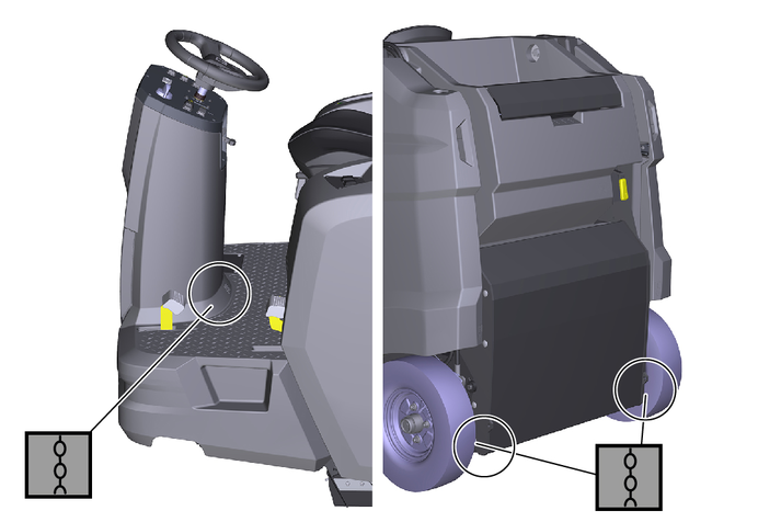
Shown on a KM 100/120 R G
Front: On the footrest in the area of the front tower.
Rear: Openings (ø approx. 30 mm) on the left and right in the frame between the rear wheels and the waste container.
The fixing points are marked by chain symbols. Only use the marked fixing points for lashing, otherwise the machine will be damaged.
Risk of injury or damage due to non-observance of the weight!
Risk of injury and damage due to non-observance of the weight during transport and storage of the machine.
Be aware of the weight of the machine during transport and storage.
Secure the machine against slipping and tipping during transport in accordance with the applicable regulations.
Empty the waste container, see chapter Emptying the waste container.
Clean the inside of the machine, see chapter Cleaning the interior of the machine.
Clean the exterior of the machine, see chapter Cleaning the exterior of the machine.
Park the machine on a flat, horizontal surface in a dry, frost-free environment.
Turn the key in the key switch to position "O" and remove it.
Disconnect the power supply, see chapter Disconnecting/connecting the power supply.
Charge the battery, see chapter Charging the battery.
Repeat the charging process every 6 weeks, otherwise the battery may be damaged.
Cover the machine dust-tight.
Danger to life, risk of injury and damage!
During care and maintenance of the machine, there is a danger to life, and risk of injury and damage if the safety instructions are not observed!
Adhere to the safety instructions for care and maintenance in the Safety instructions chapter at the beginning of these operating instructions.
Short-circuits or other damage. Do not clean the device with a hose or high-pressure water jet.
Improper cleaning
Risk of damage.
Do not use any abrasive or aggressive detergents.
Health risk from dust
For interior cleaning with compressed air.
Wear a dust mask and safety goggles.
Open the left and right panels, see chapter Open/close the left/right cladding.
Don personal protective equipment (safety goggles, face shield, respirator, hearing protection etc).
Blow out the machine with compressed air.
Clean the interior of the machine with a cloth moistened with mild washing lye.
Close the left and right panels, see chapter Open/close the left/right cladding.
Clean the exterior of the machine with a cloth moistened with mild washing lye.
To preserve eligibility for warranty claims, all servicing and maintenance work during the warranty period has to be performed by an authorised service department, in accordance with the inspection checklist (ICL).
The operating hour counter indicates the time of the maintenance intervals.
The intervals for service and maintenance work by the customer/operator are listed in the chapter Maintenance by the customer. The work must be carried out by qualified staff. If necessary, consult a Kärcher specialist dealer or service department.
Further maintenance work must be carried out by the authorised service department according to the inspection checklist. Please contact the service department in good time.
The following maintenance work must be carried out by a qualified specialist. Consult a Kärcher specialist dealer or Service provider if necessary.
Work on the hydraulics may only be carried out by the authorized Service provider.
Daily:
Carry out the safety check before starting, see chapter Safety check before startup.
Charge a discharged battery, check the electrolyte level and correct if necessary, see chapter Charging the battery.
Weekly:
Risk of injury if the waste container falls!
The raised waste container can fall abruptly and cause serious injuries due to crushing and trapping.
Do not walk underneath the waste container if it is unsecured.
Secure the raised waste container properly with the supplied safety brace before walking underneath the waste container.
Check all moving parts for ease of motion and have them lubricated or repaired if necessary.
Before performing any maintenance or repair work on the waste container while it is raised, install the safety brace, see chapter Installing/removing the waste container safety brace.
Check the sealing strips on the roller brush box for correct adjustment and wear, if necessary correct the adjustment and replace worn sealing strips, see chapter Adjusting/removing/installing the sealing strips.
Check the 3 sealing strips on the waste container flap for damage, replace if necessary.
Check the roller brush for wear and damage and replace if necessary, see chapter Removing/checking/installing the roller brush.
Check the side brush(es) for wear and damage, replace if necessary, see chapter Checking/removing/installing the side brushes.
Check the dust filter for dirt and damage, replace if necessary and clean the dust filter box, see chapter Removing/cleaning/installing the dust filter.
Check the hydraulic system for leaks and have it repaired if necessary.
Check the drive belt of the blower wheel for wear and damage, and replace if necessary.
Monthly:
Check the battery for deviations in electrolyte density and temperature between the battery cells according to the battery manufacturer's operating instructions, contact the Service provider if necessary.
To preserve eligibility for warranty claims, all servicing and maintenance work during the warranty period has to be performed by an authorised Service provider in accordance with the inspection check list.
Initial inspection after 20 operating hours
Maintenance every 100 operating hours
Maintenance every 300 operating hours
If necessary, but at least annually, have the insulation resistance of the machine and battery checked by a qualified electrician in accordance with the battery manufacturer's operating instructions.
Due to the floating mounting of the roller brush, the sweeping level automatically adjusts itself when the bristles are worn.
Switch off the machine, see chapter Switching off the machine.
Removing:
Open the left-hand cladding, see chapter Open/close the left/right cladding.
Unscrew the left knurled screw.
Pull out the bearing plate.
Unscrew the right knurled screw.
Pull off the cover plate.
Pull out the roller brush.
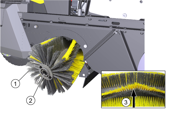
Check:
Check the roller brush for wear, damage and wrapped flexible objects such as ribbons, strings, etc. Replace the roller brush if it is worn, damaged or the cleaning result is not satisfactory, or remove wrapped objects.
Installing:
Install the roller brush.
Ensure correct alignment, the tips of the arrow-shaped tapered bristle strips must point in the travel direction when driving forwards.
Install the cover plate.
Tighten the right knurled screw.
Install the bearing plate.
Tighten the left knurled screw.
Close the left-hand cladding, see chapter Open/close the left/right cladding.
The floating bearing of the side brushes ensures that the sweeping pattern automatically adjusts itself when the bristles are worn.
Switch off the machine, see chapter Switching off the machine.
Check:
Check the side brush for wear, damage and wrapped flexible objects such as ribbons, cords, etc. Replace the side brush if it is worn, damaged or if the cleaning result is not satisfactory, or remove wrapped objects.
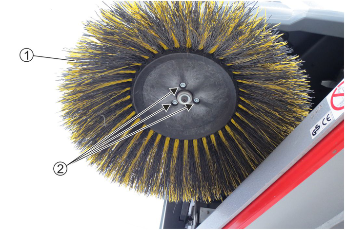
Removal:
Unscrew the screws.
Remove the side brush.
Clean the side brush holder.
Installation:
Attach the new side brush to the side brush holder.
Tighten the screws.
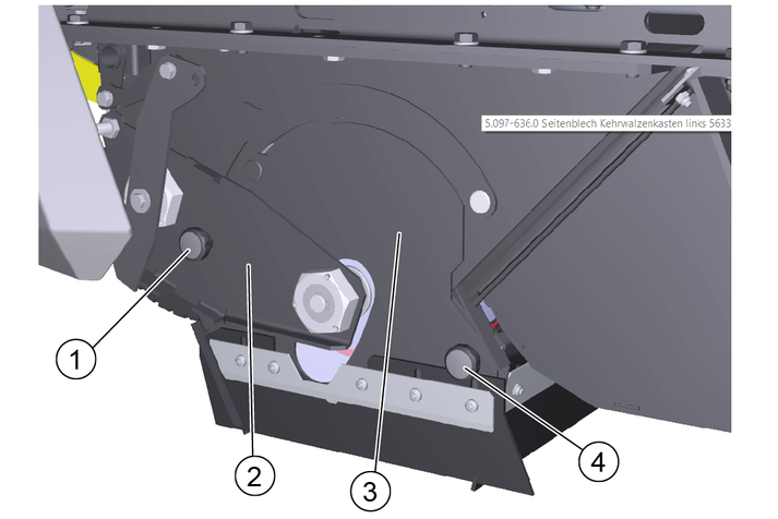
The trailing distance of the front and rear sealing strip defines how much the sealing strips fold backwards when driving the device forwards.
Adjust the side sealing strips accordingly; for adjustment values, see table Adjustment values sealing strips.
Switch off the machine, see chapter Switching off the machine.
Setting:
Open the corresponding cladding, see chapter Open/close the left/right cladding.
Loosen the screws or nuts on the fixing plate of the corresponding sealing strip.
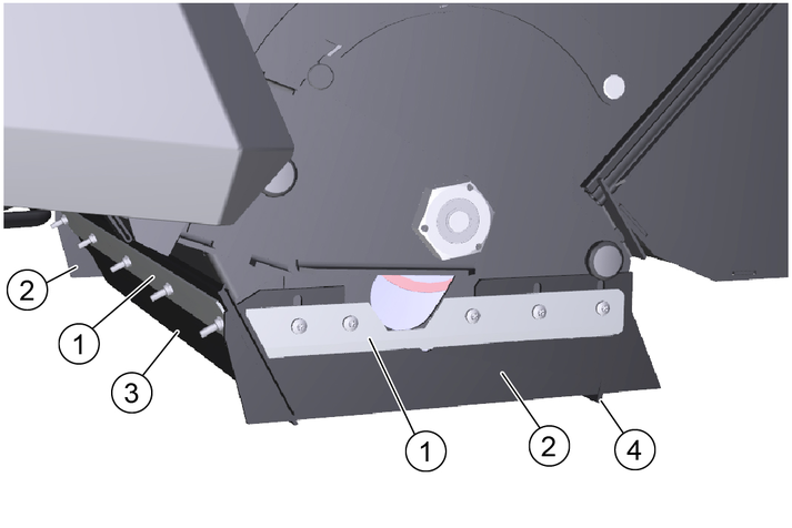
Adjust the appropriate sealing strip by shifting it in the elongated holes.
Tighten the screws or nuts on the fixing plate of the corresponding sealing strip.
Removing/installing:
Unscrew the screws or nuts on the fixing plate of the corresponding sealing strip.
Remove the fixing plate and the sealing strip.
Installation is performed in reverse sequence.
Adjust the sealing strip before tightening the screws or nuts.
Close the left or right-hand cladding, see chapter Open/close the left/right cladding.
Sealing strip | Adjustment value |
|---|---|
Side sealing strip | Distance from ground 1–3 mm |
Front sealing strip | Trailing distance 10-15 mm |
Rear sealing strip | Trailing distance 5-10 mm |
Health risk from dust
Wear a dust mark and safety goggles when working on the filter system.
Observe the safety instructions on the handling of fine dust.
Switch off the machine, see chapter Switching off the machine.
Removing:
Wait at least 1 minute until the automatic dust filter cleaning has finished and the dust has settled in the filter box.
Grasp the recessed grip and swing the storage area upwards.
Move the lever to the right into the lock.
Remove the dust filter upwards.
Cleaning:
Check the dust filter for dirt and damage, clean or replace if necessary.
Do not clean or brush out the dust filter with compressed air. To clean, gently tap or vacuum.
Installing:
Installation is performed in reverse sequence.
Danger of death when lifting the machine!
A danger of death from slipping off the jack exists when lifting the machine.
Never sit or lie down under the raised machine.
Only lift the machine when it is standing on firm, horizontal ground and secure the machine against rolling away.
Only lift the machine with suitable jacks designed for the weight of the machine.
Only use jacks at the points marked on the vehicle frame.
Removing:
Park the machine on a firm, horizontal surface.
Switch off the machine, see chapter Switching off the machine.
Open the corresponding cladding, see chapter Open/close the left/right cladding.
Use chocks to secure the opposite rear wheel against rolling away.
Loosen the wheel screw approx. 1 turn anticlockwise, e.g. with a spider wrench.
Attach a suitable jack to the jacking point and raise the machine until the rear wheel can rotate freely.
For machine weights, see chapter Technical data.
Unscrew the wheel screw and remove it together with the washer.
Remove the rear wheel from the wheel hub.
Have the defective rear wheel repaired in a specialist workshop or have it replaced.
Installing:
Put the rear wheel on the wheel hub.
Hand-tighten the wheel screw together with the washer, e.g. with a spider wrench, in a clockwise direction.
Lower the machine.
Tighten the wheel screw.
Tightening torque: 56 Nm.
Close the corresponding cladding, see chapter Open/close the left/right cladding.
Remove the chocks.
Have the removal and installation of the front wheel carried out by a Service provider.
The machine's hydraulic system is a closed system with no material consumption. As long as there are no leaks, it is not necessary to check the hydraulic oil level. If leaks or malfunctions are detected, inform the Service provider and have the hydraulic system repaired.
Installation:
Park the machine on a firm, horizontal surface.
Lower the waste container completely, see chapter Emptying the waste container.
Switch off the machine, see chapter Switching off the machine.
Open the right-hand panel, see chapter Open/close the left/right cladding.
Remove the safety brace.
Pull the cotter pins out of the bolts.
Pull out the bolts and remove the safety brace on the tie bar.
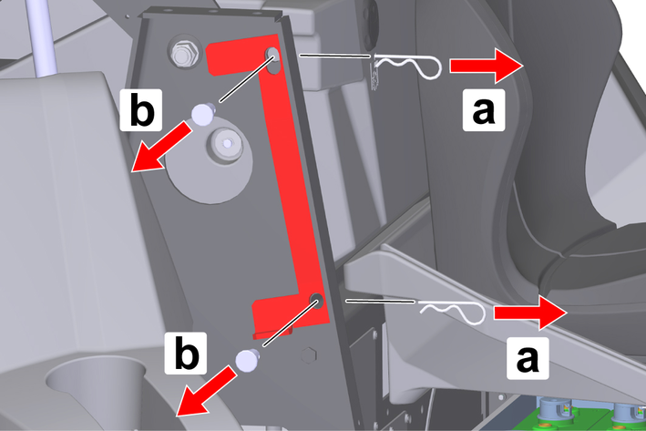
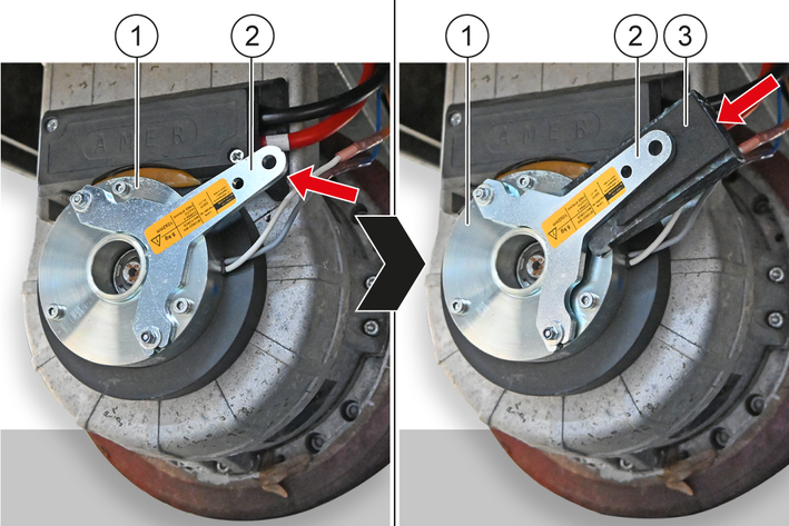
Position the safety brace between the right-hand tie bar and the right-hand lift arm as shown.
Install the bolts.
Insert the bolts into the holes.
Insert the cotter pins into the holes in the bolts until the cotter pins engage.

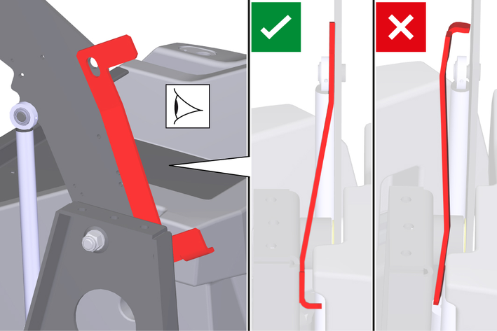
Risk of damage!
Raising or lowering the waste container with the safety brace installed causes damage to the machine and the safety brace! To prevent the waste container from being raised or lowered hydraulically, it is not possible to close the right-hand panel when the safety brace is fitted. This activates the safety circuit.
Do not close the right-hand panel by force!
Removal:
Removal is performed in the reverse sequence.
Risk of injury and damage when working on live parts!
Working on live parts of the machine may result in injury from electric shock and damage to the machine.
Switch off the machine, disconnect the mains plug of the charger from the mains socket and disconnect the power supply to the machine before carrying out inspection, maintenance or cleaning work.
Have repairs to live components carried out only by an authorised customer service.
Risk of injury due to sudden start-up of motors and systems!
When the machine is switched on, motors or systems can start abruptly and cause injuries due to e.g. jamming, crushing or shearing.
Switch off the machine and remove the key from the key-operated switch before carrying out any inspection, maintenance or cleaning work.
You can remedy minor faults using the following overview.
Contact the Service department in the case of any faults not listed!
Risk of damage if unsuitable fuses are used!
If fuses are used that do not comply with the manufacturer's specifications, electrical and electronic components can be irreversibly damaged.
Only use fuses that comply with the manufacturer's specifications in terms of shape (plug-in fuse, strip fuse) and amperage (A).
If a function fails, check the corresponding fuse and replace it if necessary. If necessary, contact the service department.
Removing:
Switch off the machine, see chapter Switching off the machine.
Disconnect the power supply, see chapter Disconnecting/connecting the power supply.
Open the left-hand cladding, see chapter Open/close the left/right cladding.
Unscrew the screw.
Pull the cover of the electronics box slightly forwards, unhook it from the latching hook at the back and remove it.
Identify the defective fuse.
Remove the corresponding fuse cover.
Remove the fuse.
Plug-in fuse: Pull the plug-in fuse out of the fuse holder.
Strip fuse: Unscrew the nuts and remove the remains of the strip fuse from the fuse holder.
Installing:
Install the fuse.
Plug-in fuse: Insert the plug-in fuse into the fuse holder as far as it will go.
Strip fuse: Insert the strip fuse into the fuse holder and tighten the nuts.
Fit the safety cover.
Mount the cover of the electronics box on the latching hook and push backwards.
Tighten the screw.
Close the left-hand cladding, see chapter Open/close the left/right cladding.
Connect the power supply, see chapter Disconnecting/connecting the power supply.
The machine does not run.
Cause:
The power supply to the machine is interrupted.
Remedy:
Sit in the driver's seat in order to activate the seat contact switch.
Check whether the emergency stop switch has been pressed, if necessary unlock the emergency stop switch, see chapter Emergency stop switch.
Turn the key in the key switch to position "I".
Read the battery charge status in the display, charge the battery if necessary, see chapter Charging the battery.
Check that the left and right-hand claddings are closed, close if necessary, see chapter Open/close the left/right cladding.
Check whether the battery connector is correctly plugged together, if necessary plug it together correctly, see chapter Disconnecting/connecting the power supply.
Check the fuses, replace if necessary, see chapter Removing/installing the fuse.
If the machine still does not run, inform the service department.
Dust generation when sweeping / insufficient suction power.
Cause:
The waste container is full.
Remedy:
Empty the waste container, see chapter Emptying the waste container.
Cause:
The dust filter is clogged.
Remedy:
Clean the dust filter, replace if heavily contaminated, see chapter Removing/cleaning/installing the dust filter.
Cause:
The dust filter is damaged.
Remedy:
Replace the dust filter, see chapter Removing/cleaning/installing the dust filter.
Cause:
The dust filter is installed incorrectly.
Remedy:
Install the dust filter correctly, see chapter Removing/cleaning/installing the dust filter.
Cause:
The sealing strips on the roller brush box are incorrectly adjusted.
Remedy:
Adjust the sealing strips correctly, see chapter Adjusting/removing/installing the sealing strips.
Cause:
The sealing strips on the roller brush box are worn.
Remedy:
Replace the sealing strips, see chapter Adjusting/removing/installing the sealing strips.
Cause:
The seals on the filter box are loose or damaged.
Remedy:
Have the seals on the filter box replaced by the service department or have them fitted correctly.
Cause:
The sealing strips on the waste container flap are loose or damaged.
Remedy:
Have the sealing strips on the waste container flap replaced or fitted correctly by the service department.
The cleaning result is unsatisfactory.
Cause:
The side brush is worn out.
Remedy:
Replace the side brush, see chapter Checking/removing/installing the side brushes.
Cause:
The roller brush is worn out.
Remedy:
Replace the roller brush, see chapter Removing/checking/installing the roller brush.
Cause:
The sealing strips on the roller brush box are incorrectly adjusted.
Remedy:
Adjust the sealing strips correctly, see chapter Adjusting/removing/installing the sealing strips.
Cause:
The sealing strips on the roller brush box are worn.
Remedy:
Replace the sealing strips, see chapter Adjusting/removing/installing the sealing strips.
Cause:
The wet sweeping flap is open.
Remedy:
Close the wet sweeping flap.
Cause:
The coarse dirt flap is open.
Remedy:
Have the coarse dirt flap repaired by the service department.
The roller brush or side brush does not rotate.
Cause:
The power supply to the machine is interrupted.
Remedy:
Connect the power supply, see chapter The machine does not run.
Cause:
The "Driving" program is set.
Remedy:
Set the program selection switch to "Sweeping with roller brush" or "Sweeping with roller brush and side brush", see chapter Program selection switch.
Cause:
The roller brush or side brushes are blocked.
Remedy:
Check the roller brush or side brush for wrapped, flexible objects such as ribbons, cords etc. and remove them, see chapter Removing/checking/installing the roller brush and Checking/removing/installing the side brushes.
Cause:
The waste container is not completely lowered.
Remedy:
Lower the waste container completely, see chapter Emptying the waste container.
The waste container cannot be emptied.
Cause:
The power supply to the machine is interrupted.
Remedy:
Connect the power supply, see chapter The machine does not run.
Cause:
The two-hand operation for safe emptying of the waste container was not considered.
Remedy:
Empty the waste container in two-hand operation, see chapter Emptying the waste container.
Cause:
The left and right shear locking screw on the waste container are sheared off.
Remedy:
Have the shear locking screws replaced by the service department.
Cause:
The program "Sweeping with roller brush" or "Sweeping with roller brush and side brushes" is set.
Remedy:
Set the program selector switch to "Drive", see chapter Program selection switch
The right-hand panel cannot be closed.
Cause:
The waste container is secured with the safety brace.
Remedy:
Remove the safety brace, see chapter Installing/removing the waste container safety brace.
The following is an excerpt of wear parts and optionally available accessories.
Wear parts and accessories | Description/note | Order no. |
|---|---|---|
Side brush, Standard | For indoor and outdoor surfaces. | 6.905-986.0 |
Side brush, soft | For fine dust on indoor and outdoor surfaces. Moisture resistant | 6.906-133.0 |
Side brush, hard | For removal of stubborn dirt outdoors. Moisture resistant | 6.906-065.0 |
Roller brush, Standard | For indoor and outdoor surfaces. Wear and moisture resistant | 6.905-095.0 |
Roller brush, soft | For fine dust on indoor and outdoor surfaces. Moisture resistant | 6.905-190.0 |
Roller brush, hard | For removal of stubborn dirt outdoors. Moisture resistant | 6.905-191.0 |
Dust filter | 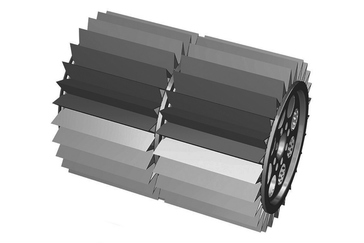 | 6.414-532.0 |
Sealing strip, side Left and right |  | 5.365-078.0 |
Sealing strip, rear |  | 5.365-053.0 |
Sealing strip, front |  | 5.294-000.0 |
Rear wheel | As a replacement. | 6.435-845.0 |
Battery 24 V, 240 Ah | 6.654-112.0 |
Accessories | Description/note | Order no. |
|---|---|---|
Charger, portable | 6.654-442.0 | |
Wheel set, non-marking | 2.853-048.0 | |
Attachment kit for side brush, left | * | 2.852-913.0 |
Attachment kit for overhead guard | * | 2.852-828.0 |
Attachment kit for spraying system | * | 2.852-835.0 |
Attachment kit for flashing beacon | * | 2.852-911.0 |
Attachment kit for work light | * | 2.852-904.0 |
Attachment kit for spotlight | * | 2.852-995.0 |
Attachment kit for impact protection | * | 2.852-491.0 |
Attachment kit for rear light | * | 2.853-042.0 |
Attachment kit for suction holder | * | 2.853-030.0 |
Attachment kit for additional side brushes | * | 2.853-034.0 |
Home Base accessories | Description/note | Order no. |
|---|---|---|
Adapter | For fixing accessories to the Home Base rail. | 5.035-488.0 |
Double hook | Can only be used in conjunction with the adapter. | 6.980-077.0 |
Detergent container | Can only be used in conjunction with the adapter. | 4.070-006.0 |
Home Base Kit coarse dirt pliers | Coarse dirt pliers with fastening parts. | 4.035-524.0 |
* Installation by the service department required.
The warranty conditions issued by our sales company responsible apply in all countries. We shall remedy possible malfunctions on your device within the warranty period free of cost, provided that a material or manufacturing defect is the cause. In a warranty case, please contact your dealer (with the purchase receipt) or the next authorised customer service site.
You can find more detailed information at: www.kaercher.com/dealersearch
Device performance data | |
Travel speed (max.) | 5,5 km/h |
Working speed (max.) | 5,5 km/h |
Climbing ability (max.) | 12 % |
Working width without side brushes | 730 mm |
Working width with 1 side brushes | 1000 mm |
Working width with 2 side brushes | 1280 mm |
Degree of protection | IPX 3 |
Theoretical surface performance | |
Surface performance without side brushes | 4015 m2/h |
Surface performance with 1 side brushes | 5500 m2/h |
Surface performance with 2 side brushes | 7040 m2/h |
Battery | |
Battery type | – |
Battery capacity | – Ah |
Charging time when the battery is completely discharged | – h |
Operation duration with fully loaded battery | – h |
Working voltage of the battery | – V |
Battery weight | – kg |
Electrolyte content | – l |
Charger | |
Mains voltage | – V |
Output voltage | – V |
Output current | – A |
Ambient conditions | |
Ambient temperature | -5 ... +40 °C |
Humidity, non-condensing | 20 ... 90 % |
Dimensions and weights | |
Length | 1660 mm |
Width | 1110 mm |
Height | 1355 mm |
Net weight | 490 kg |
Net weight (transport weight) | 490 kg |
Approved total weight | 1060 kg |
Width of roller brush | 730 mm |
Diameter of roller brush | 285 mm |
Diameter of side brush | 410 mm |
Waste container | |
Waste container volume | 120 l |
Max. waste container payload | 150 kg |
Discharge height (max.) | 1520 mm |
Filter and suction system | |
Filter area of dust filter | 6 m2 |
Usage category | U |
Engine (electric) | |
Engine type | Permanent magnet DC motor for forward and reverse travel |
Type | Wheel hub motor in front wheel |
Nominal voltage | 24 V |
Rated current | 40 A |
Nominal power (mechanic) | 780 W |
Engine speed | Infinitely adjustable 1/min |
Degree of protection | IP 44 |
Side brush engine (electric) | |
Engine type | Permanent magnet DC motor |
Type | Geared motor (angular gear) |
Nominal voltage | 24 V |
Rated current | 8,5 A |
Nominal power (mechanic) | 80 W |
Side brush speed | 80 1/min |
Degree of protection | IP 44 |
Blower and roller brush motor (electric) | |
Engine type | Permanent magnet DC motor |
Type | B14 |
Nominal voltage | 24 V |
Rated current | 32 A |
Nominal power (mechanic) | 600 W |
Speed | 3500 1/min |
Degree of protection | IP 54 |
Tyres | |
Tyre size, front | ø 300 mm |
Tyre size, rear | 4.00-8 |
Tyre pressure | 0,6 (6) MPa (bar) |
Determined values in acc. with EN 60335-2-72 | |
Hand-arm vibration value | 1,4 m/s2 |
Hand-arm vibration value, uncertainty K | 0,2 m/s2 |
Seat vibration value | 0,3 m/s2 |
Seat vibration value, uncertainty K | 0,1 m/s2 |
Sound pressure level LpA | 74 dB(A) |
LPA and LWA uncertainty | 3 dB(A) |
Sound power level LwA | 92 dB(A) |
Sound power level LWA + uncertainty LWA | 94 dB(A) |
Device performance data | |
Travel speed (max.) | 5,5 km/h |
Working speed (max.) | 5,5 km/h |
Climbing ability (max.) | 12 % |
Working width without side brushes | 730 mm |
Working width with 1 side brushes | 1000 mm |
Working width with 2 side brushes | 1280 mm |
Degree of protection | IPX 3 |
Theoretical surface performance | |
Surface performance without side brushes | 4015 m2/h |
Surface performance with 1 side brushes | 5500 m2/h |
Surface performance with 2 side brushes | 7040 m2/h |
Battery | |
Battery type | 24 V 4 HPzS 240, lead acid, low maintenance |
Battery capacity | 240 Ah |
Charging time when the battery is completely discharged | 10 ... 15 h |
Operation duration with fully loaded battery | 3,5 h |
Working voltage of the battery | 24 V |
Battery weight | 195 kg |
Electrolyte content | 38 l |
Charger | |
Mains voltage | 230 V |
Output voltage | 24 V |
Output current | 30 A |
Ambient conditions | |
Ambient temperature | -5 ... +40 °C |
Humidity, non-condensing | 20 ... 90 % |
Dimensions and weights | |
Length | 1660 mm |
Width | 1110 mm |
Height | 1355 mm |
Net weight | 490 kg |
Net weight (transport weight) | 684 kg |
Approved total weight | 1060 kg |
Width of roller brush | 730 mm |
Diameter of roller brush | 285 mm |
Diameter of side brush | 410 mm |
Waste container | |
Waste container volume | 120 l |
Max. waste container payload | 150 kg |
Discharge height (max.) | 1520 mm |
Filter and suction system | |
Filter area of dust filter | 6 m2 |
Usage category | U |
Engine (electric) | |
Engine type | Permanent magnet DC motor for forward and reverse travel |
Type | Wheel hub motor in front wheel |
Nominal voltage | 24 V |
Rated current | 40 A |
Nominal power (mechanic) | 780 W |
Engine speed | Infinitely adjustable 1/min |
Degree of protection | IP 44 |
Side brush engine (electric) | |
Engine type | Permanent magnet DC motor |
Type | Geared motor (angular gear) |
Nominal voltage | 24 V |
Rated current | 8,5 A |
Nominal power (mechanic) | 80 W |
Side brush speed | 80 1/min |
Degree of protection | IP 44 |
Blower and roller brush motor (electric) | |
Engine type | Permanent magnet DC motor |
Type | B14 |
Nominal voltage | 24 V |
Rated current | 32 A |
Nominal power (mechanic) | 600 W |
Speed | 3500 1/min |
Degree of protection | IP 54 |
Tyres | |
Tyre size, front | ø 300 mm |
Tyre size, rear | 4.00-8 |
Tyre pressure | 0,6 (6) MPa (bar) |
Determined values in acc. with EN 60335-2-72 | |
Hand-arm vibration value | 1,4 m/s2 |
Hand-arm vibration value, uncertainty K | 0,2 m/s2 |
Seat vibration value | 0,3 m/s2 |
Seat vibration value, uncertainty K | 0,1 m/s2 |
Sound pressure level LpA | 74 dB(A) |
LPA and LWA uncertainty | 3 dB(A) |
Sound power level LwA | 92 dB(A) |
Sound power level LWA + uncertainty LWA | 94 dB(A) |
EU Declaration of Conformity
We hereby declare that the machine described below complies with the relevant basic safety and health requirements in the EU Directives, both in its basic design and construction as well as in the version placed in circulation by us. This declaration is invalidated by any changes made to the machine that are not approved by us.
Product: Sweeper vacuum
Type: 1.280-xxx
Currently applicable EU Directives2006/42/EC (+2009/127/EC)
2000/14/EC
2014/30/EU
2014/53/EU (TCU)
Harmonised standards usedEN 60335-1
EN 60335-2-72
EN 62233: 2008
EN 55012: 2007 + A1: 2009
EN 61000-6-2: 2005
TCUEN 301 511 V12.5.1
EN 300 440 V2.1.1
EN 300 328 V2.2.2
EN 300 330 V2.1.1
EN 62311: 2008
Sound power level dB(A)KM 100/120 R BAT
Measured: 92
Guaranteed: 94
National standards used-
Applied conformity evaluation method2000/14/EG: Annex V
The signatories act on behalf of and with the authority of the company management.

Documentation supervisor:
S. Reiser
Alfred Kärcher SE & Co. KG
Alfred-Kärcher-Str. 28 - 40
71364 Winnenden (Germany)
Ph.: +49 7195 14-0
Fax: +49 7195 14-2212
Winnenden, 2022/01/01
Declaration of Conformity (UK)
We hereby declare that the product described below complies with the relevant provisions of the following UK Regulations, both in its basic design and construction as well as in the version put into circulation by us. This declaration shall cease to be valid if the product is modified without our prior approval.
Product: Sweeper vacuum
Type: 1.280-xxx
Currently applicable UK RegulationsS.I. 2008/1597 (as amended)
S.I. 2001/1701 (as amended)
S.I. 2016/1091 (as amended)
S.I. 2017/1206 (as amended) (TCU)
Designated standards usedEN 60335-1
EN 60335-2-72
EN 62233: 2008
EN 55012: 2007 + A1: 2009
EN 61000-6-2: 2005
TCUEN 301 511 V12.5.1
EN 300 440 V2.1.1
EN 300 328 V2.2.2
EN 300 330 V2.1.1
EN 62311: 2008
Sound power level dB(A)KM 100/120 R BAT
Measured: 92
Guaranteed: 94
National standards used-
Applied conformity assessment procedureS.I. 2001/1701 (as amended): Schedule 8
The signatories act on behalf of and with the authority of the company management.
Documentation supervisor:
S. Reiser
Alfred Kärcher SE & Co. KG
Alfred-Kärcher-Str. 28 - 40
71364 Winnenden (Germany)
Ph.: +49 7195 14-0
Fax: +49 7195 14-2212
Winnenden, 2022/01/01