SB MB
59801060 (04/23)
59801060 (04/23)
 Read these original instructions and the enclosed safety instructions 5.596-309.0 before using the device for the first time. Act in accordance with them.
Keep both books for future reference or for future owners.
All users: Users are instructed assistants, operators and qualified technical specialists.
Technical specialists: Technical specialists are persons possessing the necessary technical training allowing them to erect and commission the system.
Knowledge of the following terms is important for understanding the operating instructions. The technical terms in bold are used throughout these operating instructions.
Fresh water - raw water, tap water, city water
Base exchanger - WSO, water softening unit
Softened water - soft water
Reverse Osmosis (RO) - reverse osmosis
Concentrate - waste water enriched with salts and minerals from reverse osmosis
Permeate - osmosis water, demineralised water, deionised water
Processed water - water from a biological water treatment plant
 The packing materials can be recycled. Please dispose of packaging in accordance with the environmental regulations.
 Electrical and electronic devices contain valuable, recyclable materials and often components such as batteries, rechargeable batteries or oil, which - if handled or disposed of incorrectly - can pose a potential danger to human health and the environment. However, these components are required for the correct operation of the device. Devices marked by this symbol are not allowed to be disposed of together with the household rubbish.
Current information on content materials can be found at: www.kaercher.de/REACH
Please do not allow engine oil, heating oil, diesel and petrol to enter the environment. Please protect the ground and dispose of old oil in an environmentally friendly manner.
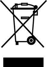
Dangers can be presented to the operator and other persons if the device is incorrectly operated or misused:
High water pressure
Hot water
Hot exhaust gases
High electrical voltage
Detergent
To avoid danger to persons, animals and property, read the following documents before operating the system:
These operating instructions, including all safety instructions
The respectively applicable national regulations
The safety instructions provided with the detergent used
Ensure the following:
That you have understood all notes and instructions
That all users of the system are notified of the instructions and have understood them
All persons working on the erection, commissioning and operation of the system must:
Be appropriately qualified
Know and adhere to these operating instructions
Know and adhere to the applicable regulations
In self-service operation, ensure that clearly visible notices are present informing all users with regard to:
Potential dangers
Safety devices
Operating the system
When operating in confined spaces
Fumes must be discharged in approved pipes or chimneys
Adequate ventilation must be provided.
Risk of burns from hot exhaust gases
Keep body parts away from the exhaust gas opening. Do not touch the chimney cover.
Risk of burns from hot system components
Do not touch system components such as pumps and motors until they have cooled down.
Risk of injury
Do not use the system if persons without the proper protective clothing are in the vicinity.
Do not aim the jet at yourself or at others, e.g. to clean clothes or shoes.
Check the device and the accessories, such as the high-pressure hose, high-pressure gun and safety devices, to make sure they are in proper safe and reliable condition before each operation. Do not use the device if it is damaged. Replace damaged components immediately.
Only use high-pressure hoses, control panels and couplings specified by the manufacturer.
Observe the respectively applicable national regulations for liquid jet cleaners.
Observe the respectively applicable national regulations for electrical installation.
Observe the respectively applicable national regulations for accident prevention. Have the system checked annually and store the written test results in a safe place.
Allow only KÄRCHER Customer Service technicians or KÄRCHER-authorised technicians to perform maintenance work and repairs.
The heating equipment in the device is a firing system. Have the combustion system checked regularly in accordance with the respective national regulations of the legislator.
Ensure non-hazardous extraction of the exhaust gases (exhaust gas pipe without a draw interrupter) when operating the system in rooms. Ensure a supply of sufficient fresh air.
Adjustments, maintenance work and repairs on the burner may only be carried out by trained Kärcher customer service technicians.
When planning the chimney, take into account the locally applicable guidelines.
Before installing the device, the gas supply company and the district chimney sweep should be consulted.
During installation, observe the regulations of building law, trade law and emission control. We refer to the regulations, guidelines and standards listed below:
The device may only be installed by a specialist company in accordance with the respective national regulations.
The installation of the gas pipes and the gas-side connection of the device may only be carried out by a specialist company approved in the gas and water trade.
Adjustments, maintenance work and repairs on the gas burner may only be carried out by authorised specialist personnel of the burner manufacturer.
Indication of an imminent threat of danger that will lead to severe injuries or even death.
Indication of a potentially dangerous situation that may lead to severe injuries or even death.
Indication of a potentially dangerous situation that may lead to minor injuries.
Indication of a potentially dangerous situation that may lead to damage to property.
 | WARNINGDanger from high electrical voltage. Have work on system parts with this symbol carried out by a qualified electrician only. |
 | DANGERRisk of burns due to high temperature. Do not touch surfaces marked in this way. |
Risk of injury
Danger from electric shock.
The high-pressure jet can cause injuries.
Do not direct the high-pressure jet at people or animals.
Do not direct the high-pressure jet at electrical devices, cables or the system.
The maximum sound level of the system is 65dB(A). Hearing protection is therefore not usually required.
When cleaning noise-intensifying parts, the sound level may increase. For this reason, wear suitable hearing protection in such cases.
Turn the programme selection switch to "STOP".
Coins are inserted at the control panel and the washing programme is selected.
Cleaning is carried out with the high-pressure gun, washing brush and power foam lance.
Risk of injury, risk of burns
Only operate the system with the casing closed.
The inside of the system must only be accessible to trained personnel for maintenance work. When using the system, the door must be locked.
This SB washing bay is used for cleaning vehicles and trailers with water and detergent additives.
Cleaning humans and animals is improper use and
is prohibited.
The high-pressure water jet presents a substantial risk of injury.
Loose objects.
Loose objects can be propelled away at high speed by the high-pressure water jet and injure persons or damage other objects.
A category 5 system isolation must be installed between the system and the drinking water network to isolate the system from the drinking water network. Locally applicable regulations must also be observed.
Dirty water leads to premature wear or deposits in the device.
Clean the device using only clean water, or recycled water that does not exceed the following limits:
pH value: 6.5...9.5
electrical conductivity: maximum conductivity of fresh water 1000 µS/cm
Hydrocarbons: < 0.01 mg/l
Chloride: < 250 mg/l
Calcium: < 200 mg/l
Total hardness: < 28 °dH, < 50° TH, < 500 ppm (mg CaCO3/l)
Iron: < 0.2 mg/l
Manganese: < 0.05 mg/l
Copper: < 0.02 mg/l
Sulphate: < 240 mg/l
Active chloride: < 0.1 mg/l
Free of unpleasant odours
To ensure correct extraction of the burner exhaust gases, the system may only be operated outdoors. When erected under a roof or in a closed room, the system must be connected to a chimney to extract the exhaust gases. When connected to a chimney, the burner must be re-adjusted and the exhaust gas values must be check by the chimney sweep responsible.
Risk of damage
Frost can damage the system under certain circumstances.
The device is frost-proof down to -20°C under the conditions specified in the section "Frost protection" and must be shut down at lower temperatures.
For safety reasons we recommend operating the device only via a fault current protection switch (maximum 30 mA).
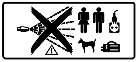
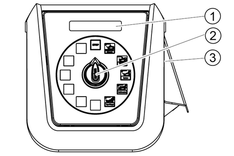
The active washing programme is selected with the programme selector switch.
The programme is interrupted.
Initial position. Cleaning tools in the tool mounts.
Note: The "STOP" function is active at all switch settings without a washing programme.
For removing coarse dirt.
Water with detergent.
Minimum high-pressure jet clearance of 30 cm.
Thorough paint cleaning with active foam.
Use the washing brush only when a program is running and after the high-pressure wash.
Clear, cold water for rinsing off shampoo and foam.
Minimum high-pressure jet clearance of 50 cm.
Warm water with paint preservation.
Use only after rinsing.
Minimum high-pressure jet clearance of 80 cm.
Stain-free drying.
Demineralized water with a shine dryer.
Minimum high-pressure jet clearance of 80 cm.
Removal of stubborn dirt.
Water with special detergent additive.
Minimum high-pressure jet clearance of 30 cm.
Removal of bitumen, tarmac, residue.
Spraying a special detergent.
Loosening of insect residue.
Warm water with insect cleaner.
Minimum high-pressure jet clearance of 30 cm.
Loosening of brake residue. Cold water with special, highly dosed detergent added with admixture of compressed air.
Used before the car wash and only on coated or painted wheel rims.
Loosening of stubborn dirt. Foam with special detergent additive.
Minimum foam jet clearance of 30 cm.
Removal of coarse dirt on the vehicle underside.
The washing process begins with a delay of approx. 10 seconds; drive the vehicle back and forth over the undercarriage wash.
Loosening of stubborn dirt.
Water with special detergent additive.
Minimum high-pressure jet clearance of 80 cm.
Loosening of brake residue.
Water with special detergent additive.
Maximum acting time of 2 minutes. Used before the car wash and only on coated or painted wheel rims.
Hot water with paint preservation. Use only after rinsing.
Minimum foam jet clearance of 80 cm.
Turn the program selection switch to the desired washing program.
Insert a coin.
While a washing programme is in progress, water will escape from the nozzle of the cleaning tool even when the high-pressure gun is not actuated. Due to the frost protection function, the high-pressure gun does not close completely.
To clean with the high-pressure jet, press the locking lever, pull the cleaning brush back and lock it in place.

To clean with the cleaning brush, press the locking lever, push the cleaning brush forwards and lock it in place.
Release the safety catch.
Pull the trigger.
This version has a high-pressure gun and cleaning brush as two separate tools.
High-pressure gun:
Release the safety catch on the high-pressure gun and pull the trigger.
Washing brush:
Clean the washing brush with the high-pressure gun before use.
Select the washing programme Foam Wash and clean the vehicle.
There are 3 separate tools here:
High-pressure gun
Cleaning brush
Power foam lance
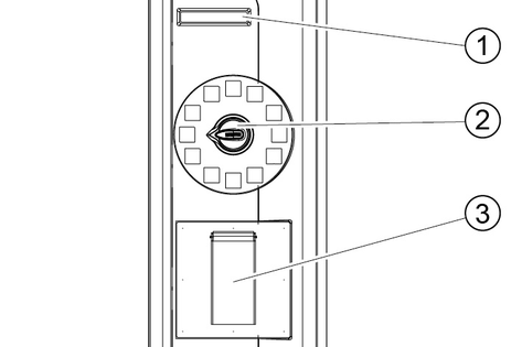
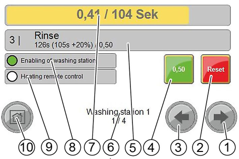
The washing time begins when a coin is inserted.
The remaining value display shows the remaining washing time in the washing units.
The washing time continues to run when the programme selection switch is in the “STOP” position.
If further coins are inserted during the washing time, these are registered and added to the existing washing time.
Position | Function |
|---|---|
1 | The system is in operation. The frost protection devices (option) are active. |
0 | The entire system is out of operation (including the frost protection devices). |
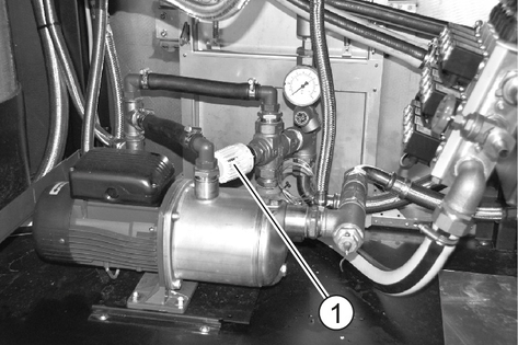
Set the pressure reducer 0.4...0.5 MPa (4...5 bar).
The dosing pumps add detergents and care agents to the washing water according to the washing programme and the equipment in the system.
The dosing quantities are adjusted optimally by the installation technician during initial commissioning. Changes to these settings are not usually necessary.
Fine adjustments are made on the controller (see "Controller/Menu Settings/Menu/ Washing programme settings"). The standard setting of the dosing pumps is not changed.
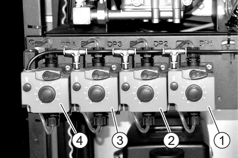
Pull out the dosing amount adjustment knob.
Alternately press and release the ventilation button while turning the adjustment knob to the desired setting.
Washing program | Detergent | Adjustment knob position(%) |
|---|---|---|
High-pressure Wash | RM 806 | 50 |
Wet foam (option) | RM 806 | 50 |
Dry foam (option) | RM 812 | 50 |
Hot wax | RM 820 | 50 |
Top care | RM 821 | 50 |
Dirt Loosening (option) | RM 806 | 50 |
Insects Loosening (option) | RM 803 | 50 |
Power foam | RM 838 | 80 |
Power rim foam | RM 802 | 80 |
Power wax | RM 820 | 50 |
Release the ventilation button.
Press in the dosing amount adjustment knob
Open the fresh water inlet.
Run the wash programme Foam Wash at a washing station.
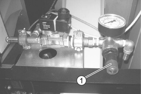
Set the water pressure reducer to 0.25 MPa (2.5 bar).
Set the dosing pump for dry foam to 20%. For the procedure, see "Setting the dosing pumps".
Open the fresh water inlet.
Remove the hose at the output of the water/chemistry distribution block and replace it with a piece of hose approx. 400 mm long (PVC hose 6/4).
Run the Foam Wash washing programme for this washing station.
Adjust the fluid flow from the hose section to 300 ml/min by adjusting the dosing valve for water/detergent (measure with measuring cylinder).
End the currently running Foam Wash washing programme.
Remove the piece of hose and reconnect the hose to the washing station.
Repeat the setting of the dosing valves for water/chemistry for the remaining washing stations.
Set the air pressure reducer to 0.25 MPa (2.5 bar).
Insert the service tool 6.901-074.0 between the air output and the hose to the washing station.
Run the Foam Wash washing programme for this washing station.
Adjust the air dosing valve so that the service tool pressure gauge reads 0.15 MPa (1.5 bar).
End the currently running Foam Wash washing programme.
Remove the service tool and reconnect the hose to the washing station to the air distribution block.
Repeat the setting of the air dosing valves for the remaining washing stations.
After the standard setting has been carried out, the consistency of the foam should only be changed by adjusting the air dosing valves.
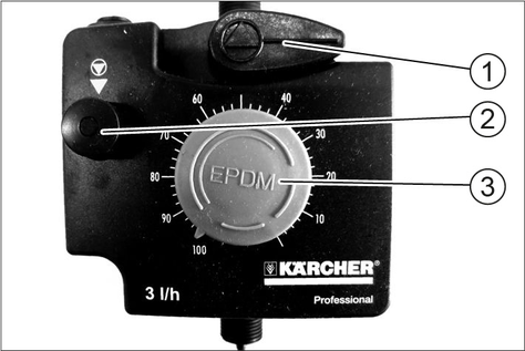
Pull out the detergent suction hose.
Select the nozzle insert for the desired mixing ratio:
Nozzle colour | Water/detergent | |
|---|---|---|
Wheel cleaning * | Intensive Foam ** | |
No nozzle | 1:1 | 4:1 |
Grey | 1.2:1 | 5:1 |
Black | 2:1 | 6:1 |
beige | 4:1 | 8:1 |
red | 6:1 | 17:1 |
White | 9:1 | 23:1 |
Blue | 10:1 | 25:1 |
light brown | 13:1 | 36:1 |
green | 21:1: | 48:1 |
orange | 26:1 | 64:1 |
brown | 30:1 | 75:1 |
yellow | 38:1 | 90:1 |
violet | 50:1 | 120:1 |
Pink | 100:1 | 240:1 |
* Hydrominder type 515 GB ** Hydrominder type 511 GB | ||
Wheel cleaning | Intensive Foam | ||
|---|---|---|---|
Detergent | RM 801 | RM 802 | RM 838 |
Nozzle colour | Blue | yellow | yellow |
Mixing ratio | 10:1 | 38:1 | 90:1 |
Insert the nozzle insert into the detergent inlet as far as it will go.
Fit the suction hose.
Adjust the pressure at the adjustment screw:
Wheel cleaning | Intensive Foam |
|---|---|
0.55...0.65 MPa (5.5...6.5 bar) | 0.8...0.85 MPa (8.0...8.5 bar) |
Set the air pressure reducer:
Wheel cleaning | Intensive Foam |
|---|---|
0.25...0.3 MPa (2.5...3 bar) | 0.3 MPa (3 bar) |
Risk of damage
Acidic detergents can damage the system.
Only use alkaline detergents to clean the wheels.
After the standard setting has been carried out, the spray pattern should only be changed by adjusting the air pressure reducer.
Even application of wheel cleaner is improved if a suitable dye is added to the wheel cleaning concentrate.
Set the pressure as required by turning the adjustment screw.
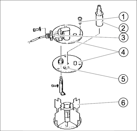
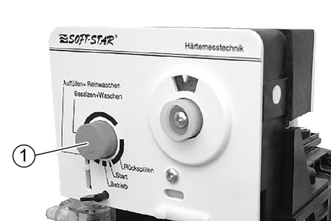
The current time must be set at the control head of the base exchanger in order that regeneration is carried out at night.
Pull out the adjustment knob and turn it until the current time is displayed.
The booster heater is supplied with partially softened water with a water hardness of 7° dH. For this purpose, the blending device mixes fresh water and softened water.
Open the stop valves for soft water and hard water completely.
Close the control valve.
Close the bypass valve.
Slightly open the float valve in the hot water float tank.
Open the bypass valve until 7°dH is measured at the mixed water output.
Open the float valve in the hot water float tank completely.
Open the control valve until 7°dH is measured at the mixed water output.
Carry out control measurements at different water removal quantities. The water hardness must be between 6°dH and 8°dH.
Two hot air blowers heat the interior of the system to provide frost protection.
Risk of fire
Hot air blowers can overheat if the air input or output is obstructed.
Do not cover the air input openings and the air output openings of the hot air blowers.
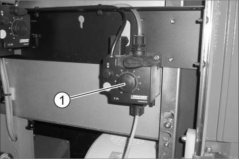
Set the power regulator and the thermostat regulator to the values recommended below depending on the expected lowest outdoor temperature.

Hot air blower | 0°C...-10°C | -10°C...-20°C | |
|---|---|---|---|
top | Power controller | II | II |
Thermostat control | II | III | |
bottom | Power controller | II | II |
Thermostat control | * | I | |
The thermostatic mixing valve regulates the flow temperature as a function of the return temperature: 22°C=scale value 3.
If necessary, correct the setting of the thermostatic mixing valve according to the following table:
Scale value | 0 | 1 | 2 | 3 | 4 | 5 |
Return temperature [°C] | 10 | 14 | 18 | 22 | 26 | 30 |
Scale value | 6 | 7 | 8 | 9 | 10 | |
Return temperature [°C] | 34 | 38 | 42 | 46 | 50 | |
This frost protection device is activated by the controller if there is a risk of frost. High-pressure lines and trigger guns have fresh water flowing through them to protect them from freezing.
Switch on the frost protection pump (see chapter "Controller/Service menu").
Set the pressure reducer so that at least 0.5 l/min of water flows from each trigger gun.
Switch off the frost protection pump.
The emergency frost protection is activated in the event of a defective frost protection pump (in systems without mains disconnection also in the event of a power failure). High-pressure lines and trigger guns have fresh water flowing through them to protect them from freezing.
Turn the main switch to position “0”.
Set the pressure reducer so that at least 0.5 l/min of water flows from each trigger gun.
The outdoor thermostat switches on the following frost protection devices depending on the outdoor temperature:
below +3°C:
the hose heating for dry foam (option)
the heating cartridge and the trace heating ABS fuel oil tank (option)
below +1°C:
the washing station heater circulation pump
the circulation pump frost protection
The switching temperature of the outdoor thermostat can be set by customer service.
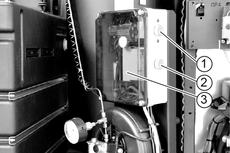
The touchscreen is mounted on the electrical box inside the system.
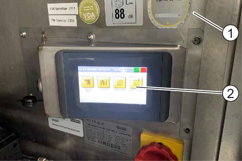
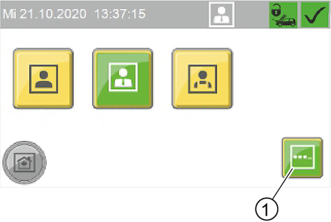
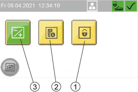
The following functions are displayed in the start menu.
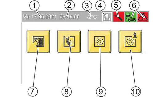
Start menu
Operating status symbols
 | System open |
 | System closed |
 | System in order |
 | Event present |
 | Malfunctions present |
User symbols
 | Operator |
 | Owner |
 | Service |
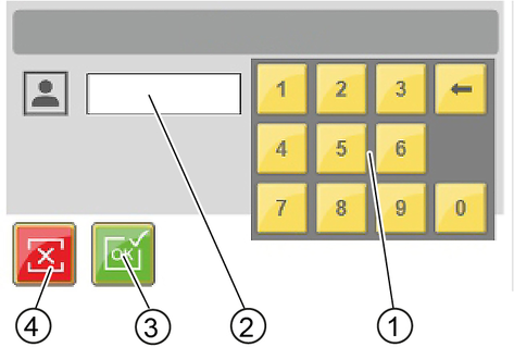
Press the Change Setting button next to the property you want to change.
 | Change Setting button |
A selection window opens to select the desired setting or a keyboard opens to enter the desired value.
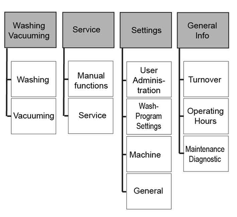
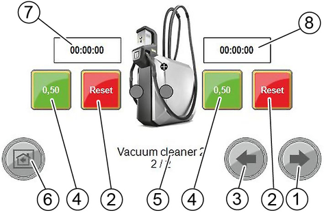
The current operating status of the individual washing stations is displayed in the Washing / Vacuuming menu.
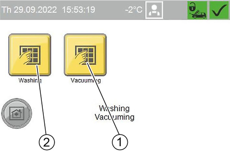
The current operating status of the washing station is displayed in the Washing menu.
The increased washing credit with this function also allows operation outside the set opening hours (e.g. for care and maintenance work).
If an additional washing time and a percentage surcharge are displayed, you are currently in "Happy Hour" mode.
The Vacuuming menu is only visible if self-service vacuum cleaners are registered with the system.
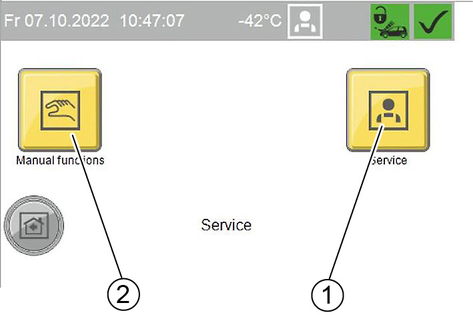
Manual functions are carried out in the Service menu.
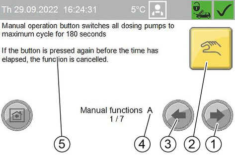
 | After starting the manual function, the symbol changes and the remaining run time is displayed below it |
List of manual functions:
A | All dosing pumps are switched on for 180 seconds. * |
B | The washing station lighting is switched on for 180 seconds. * |
C | The frost protection circuit is switched over for 10 minutes. *
|
D | The foam hose heater is activated for 180 seconds. * |
E | The washing station heater is switched on for 180 seconds. * |
F | Permeate production is started. *
|
G | The regeneration of the base exchanger is started. The regeneration cannot be cancelled. |
* If the "Start manual function" key is pressed again within the run time, the manual function is terminated.
The user group is selected in the User Administration menu. Different user groups have different access permissions
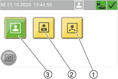
A code must be entered when selecting the user groups "Owner" and "Service".
Default code Owner: 1111
Changing code
For the user group Owner , the code can be changed after logging in.
Press the "..." button.
Enter the desired code in the "EnterNew Code" window.
Enter the same code again for confirmation in the "Confirm New Code" window.
The parameters of the individual washing programs are adjusted in the Wash-Program Settings menu.
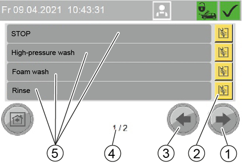
Changing the parameters of a washing program
Select the window with the desired washing program. Use the Next Window and Previous Window buttons for this.
Press the Change washing program button next to the desired wash program.
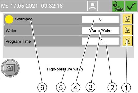
Press the button to change the desired parameter.
Press the desired parameter in the displayed selection.
Standard setting
Washing program | Dosing pump | water type | Program duration |
|---|---|---|---|
High-pressure Wash | 1 (yellow) | Warm | 90 s |
Foam Wash | 1 (yellow) | Cold | 135 s |
Rinse | - | Cold | 105 s |
Hot wax | 2 (red) | Warm | 54 s |
Insects Loosening | 3 (green) | Warm | 75 s |
Dirt Loosening | 3 (green) | Warm | 75 s |
Power foam | 3 or 4 (light green) | Warm | 60 s |
Power rim foam | 3 or 4 (white) | Cold | 60 s |
Top care | 3 or 4 (red) | Permeate | 75 s |
Washing program | Hydrominder | water type | Program duration |
|---|---|---|---|
Wheel cleaning | GB 515 | Cold | 75 s |
Intensive Foam | GB 511 | cold, soft water | 75 s |
Washing program | Detergent dosing unit dosing pump | |||
|---|---|---|---|---|
500 l/h | 900 l/h | |||
% | ml/min | % | ml/min | |
High-pressure Wash | 8 | Approx. 6 | 16 | Approx. 12 |
Foam Wash | 8 | Approx. 6 | 16 | Approx. 12 |
Rinse | - | - | - | - |
Hot wax | 10 | Approx. 7 | 20 | Approx. 14 |
Insects Loosening | 20 | Approx. 14 | 40 | about 28 |
Dirt Loosening | 20 | Approx. 14 | 40 | Approx. 28 |
Power foam | 30 | Approx. 21 | 30 | Approx. 21 |
Power rim foam | 30 | Approx. 21 | 30 | Approx. 21 |
Top care | 10 | about 7 | 20 | Approx. 14 |
Washing program | Detergent dosing unit hydrominder | |||
|---|---|---|---|---|
500 l/h | 900 l/h | |||
% | ml/min | % | ml/min | |
Wheel cleaning | 2.6 | 39 | 2.6 | 39 |
Intensive Foam | 1.1 | 26 | 1.1 | 26 |
In the Machine menu, system parameters are set and the washing station can be locked.
Various system parameters can be set in this menu.
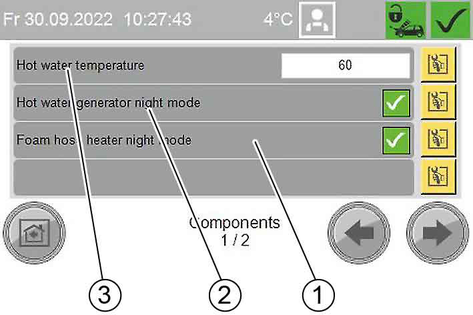
Components menu 1 of 2 (depending on the equipment of the system, 1 or more windows are displayed)
When the function is activated, the hose heating switches off at the end of operation and is switched on again 1 hour before the start of operation.
If the function is not activated, the hose heating is also switched on outside the operating time.
When the function is activated, the burner switches off at the end of operation and starts again 10 minutes before the start of operation.
If the function is not activated, the burner keeps the hot water float tank at the set temperature even outside the operating time.
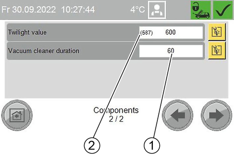
Menu Components 2 of 2
The currently measured brightness value is shown in brackets.
In the Coin value menu the wash value for 100% program run time and the coin values for the individual channels of the coin acceptor are set.
The coin values for washing stations and vacuum cleaners can be set separately
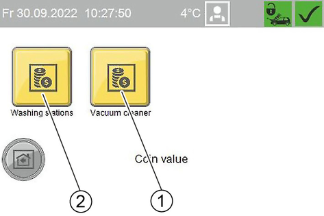
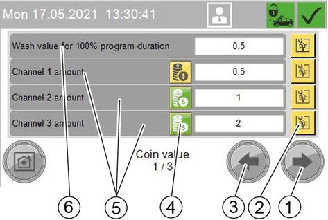
Channel ... amount: Channels of an electronic coin acceptor
External amount: Mechanical coin acceptor
External 1 amount: for example, payment system with RFID
Press the Setting button next to the desired value.
Enter the desired value.
In the Lock menu, one or more washing stations can be locked out or the lock can be cancelled.
The lock is effective regardless of the set opening hours.
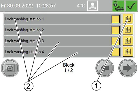
Press the Change setting button.
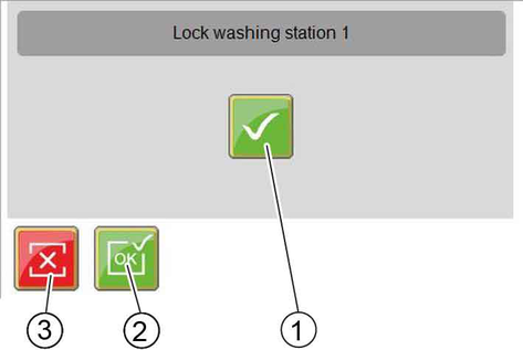
Press the desired button.
In the General menu, the time, date and operating times are set and the display language is selected.
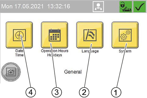
The time, date and summer time are set in the Date Time menu.
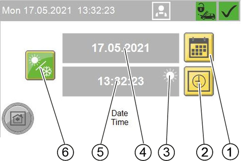
Setting the time
Press the Set Time button.
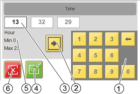
Use the Change Input Field button to select the desired input field.
Delete the field content with the delete key on the keyboard.
Enter the desired value with the keyboard.
Repeat the process until all desired changes have been made.
Exit the window.
The date is set according to the same principle as described for the time.
In the Operation Hours Holidays menu, the opening hours are set for each weekday and for public holidays. Fixed and floating holidays are also defined.
The Happy Hour function can be used to define periods with changed run times of the washing programmes.
The setting is made according to the same principle as in the Date Time menu.
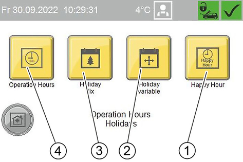
Menu Operation Hours
The opening hours are set separately for washing stations, lighting and vacuum cleaners.
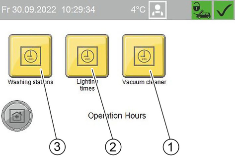
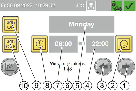
To set an opening time dependent on the time of day, the buttons for all-day operation and all-day closed must be deactivated (yellow).
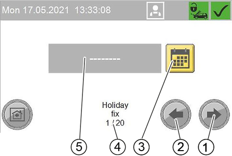
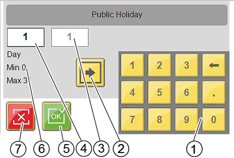
Menu Holiday fix
Fixed holidays always occur on the same date each year.
Menu Holiday variable
Floating holidays occur on a different date each year.
The setting is made according to the same principle as for Holiday fix, except that here the year must also be set.
Menu Happy Hour
In the Happy Hour menu, periods with shortened or extended washing programme run times are managed. 5 different modes can be set up.
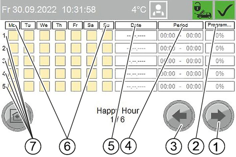
Overview Happy Hour
Window 1: Overview
Window 2...6: Mode 1...5
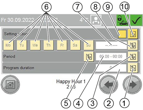
Mode setting
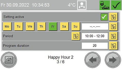
Example: Mode for Happy Hour weekly
Execution on every Friday
10:00 am to 12:00 pm
Washing times extended by 20%
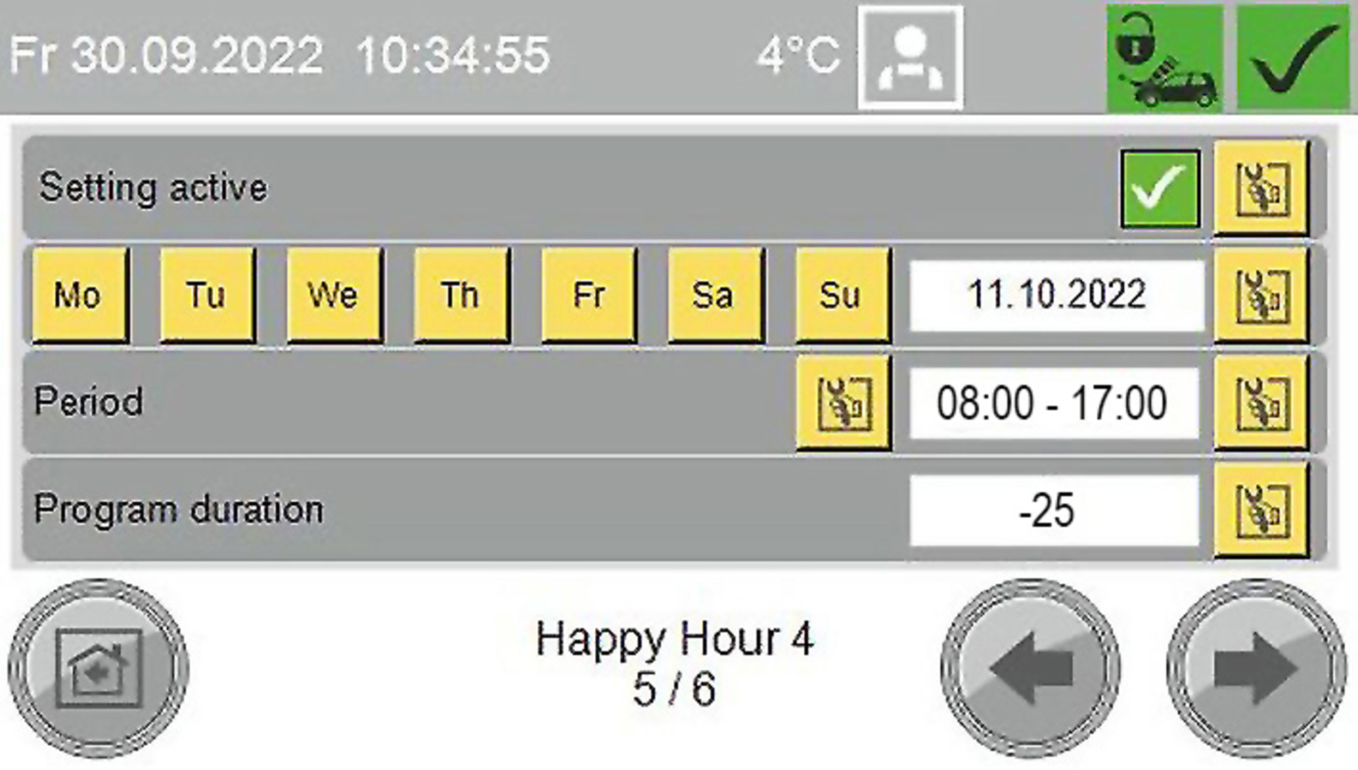
Example: Mode for Happy Hour on a specific date
Execution on 11/10/2022
8:00 am to 05:00 pm
Washing times reduced by 25%
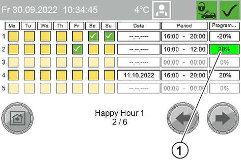
Example overview:
Mode 1: every Saturday and Sunday from 4:00 pm to 8:00 pm washing times shortened by 20%
Mode 2: every Friday from 10:00 am to 12:00 pm washing times extended by 20% (this mode is currently active)
Mode 3: not set up
Mode 4: on 11/10/2022 from 4:00 pm to 8:00 pm washing times increased by 20%
Mode 5: not set up
If there is overlap between the individual modes, the mode with the lower number is executed.
This menu is used to select the language in which the display is shown.
In the General Info menu, turnover, operating hours, maintenance information and fault messages can be viewed.
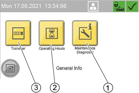
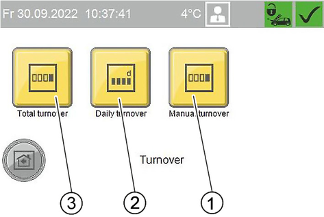
The Turnover menu shows total turnover, daily turnover and manual turnover.
The menu Manual turnover shows the washing units that have been manually upgraded in the menu Washing / Vacuuming.
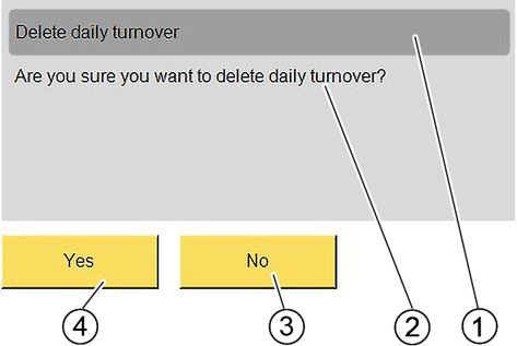
The daily turnover can be deleted.
Turnover groups
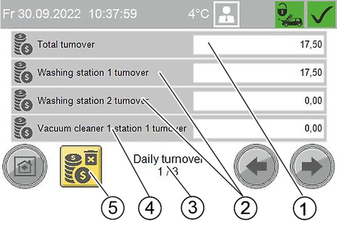
Daily turnover (depending on the equipment of the system, 1 or more windows are displayed)
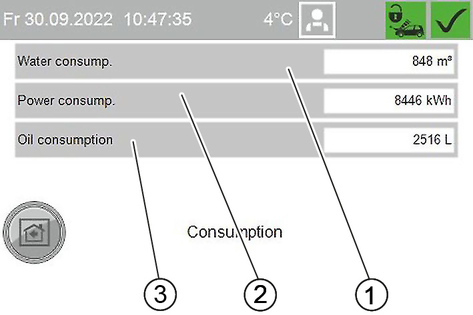
In the Operating Hours menu / Consumption is displayed:
Operating hours of the components
Operating hours of the washing stations
Consumption data of the system
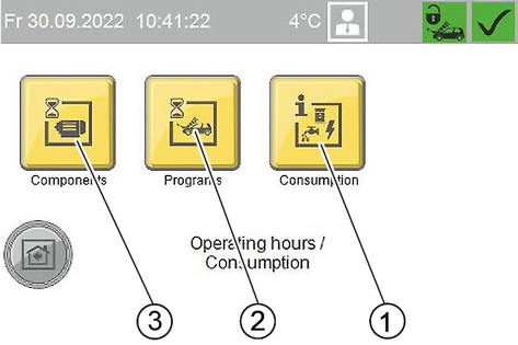
Menu Components
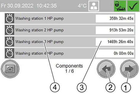
Operating hours of system components
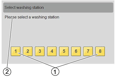
Menu Programs
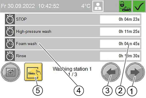
Operating times per wash programme for the first washing station of the system
Show operating times for a single washing station
Menu Consumption
The Maintenance Diagnostic menu is described in the chapter "Care and Maintenance".
Risk of damage
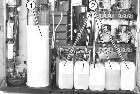
If the detergent tank is empty, the high-pressure pump sucks air and can get damaged.
Check the filling level of the detergent containers regularly.
Unsuitable detergents can damage the system and the object to be cleaned.
Use only detergents approved by KÄRCHER. Observe the dosage recommendations and instructions provided with the detergent. Use detergents sparingly to help conserve the environment.
Incorrect handling of detergents can endanger your health.
Read and observe the safety and usage instructions provided with the detergent before using the detergent. Wear the protective clothing specified in these documents.
Refill the detergent canister with the undiluted detergent.
Washing program | Detergent |
|---|---|
High-pressure Wash | RM 806 |
Wet foam (option) | RM 806 |
Dry foam (option) | RM 812 |
Hot wax | RM 820 |
Top care | RM 821 |
Wheel cleaning * (option) | RM 801 |
Wheel cleaning ** (option) | RM 802 |
Intensive Foam (option) | RM 838 |
Dirt Loosening (option) | RM 806 |
Insects Loosening (option) | RM 803 |
Power foam (option) | RM 838 |
Power rim foam *** (option) | RM 802 |
Power wax (option) | RM 820 |
* with hydrominder via high-pressure lance RM 801
** with hydrominder via changeover lance RM 802
*** with high-pressure pump and dosing pump via 3. Tool
Hang the detergent suction hose in the detergent canister.
The system compressed air supply must be in operation.
Turn the venting lever anticlockwise as far as it will go.
Set the dosing amount to 100%.
Press the ventilation button repeatedly until the detergent comes out of the venting line on the underside of the dosing pump without bubbles.
Reset the dosing quantity to the desired value, see "Settings / Setting the dosing pumps / Standard setting".
Turn the venting lever clockwise as far as it will go.
Risk of fire
Fuel can ignite.
Observe the locally applicable regulations on the handling of fuel.
Do not use unsuitable fuels as they can be dangerous.
Risk of damage
Burner faults
Fuel overflow
If the fuel tank is empty, the fuel pump runs dry and can get damaged.
Incorrect fuel can lead to burner faults and poor combustion.
Fuel expands when warmed and can overflow.
Check the fuel tank filling level regularly.
Only use the fuel specified in the "Technical data" section.
Use heating oil with a winter operation additives (flow improvers) if there is a risk of frost.
Do not fill the fuel container to the brim.
Unscrew the cap of the filling nozzle.
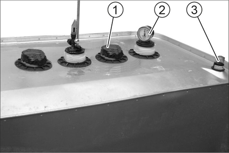
Fill with fuel until the filling level display shows full.
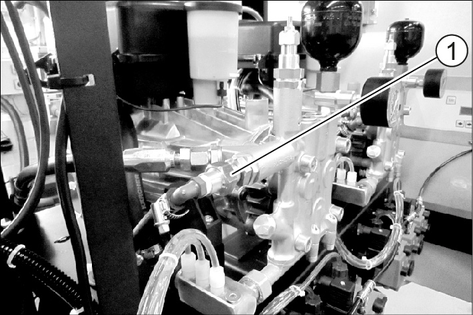
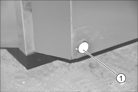
Make sure that no fuel overflows and gets into the inspection opening. During a later inspection, this fuel could be mistaken for leakage.
Close the filling nozzle.
Malfunctions possible
Unsuitable salt can interfere with the function of the base exchanger.
Only use the softening salt in tablet form specified in the "Accessories" chapter.
Remove the lid of the salt tank.
Fill the salt tank to the top with softening salt.
Fit the lid of the salt tank.
An empty salt tank causes malfunction. Fill up the salt tank at the latest when water is visible in the salt tank after removing the lid.
Salt consumption does not increase when the salt tank is completely full.
In a correctly working system, the salt consumption is constant in relation to the water consumption.
We recommend documenting the salt and water consumption in an operating log.
The frost protection device consists of:
Recirculation fan
Hot air blower
Frost protection circuit or frost protection with water loss
Washing station heater
Emergency frost protection
Heating cartridge in the oil tank
Danger of accident
If there is black ice, there is a risk of accidents for the users of the washing bay.
Lock out washing stations when black ice forms to prevent black ice accidents.
The following features are guaranteed:
Unrestricted washing with the high-pressure spray lance down to -15°C. For systems with 4 washing stations, it is recommended to lock out one washing station below -10°C (for systems with 4 high-pressure modules type 908 already at warmer temperatures).
Restricted washing with the washing brush at temperatures below 0°C. During restricted washing, all washing brushes must be checked regularly for icing. Foam washing with an iced washing brush can damage the vehicle. If the washing brush is iced up, the following measures must be taken:
1-tool version: Replace the combination spray lance with a high-pressure spray lance.
2-tool version (option): Refrain from foam washing (e.g. by giving instructions to the user).
At temperatures below –15°C, washing makes no sense because an ice coating forms on the vehicle. This ice coating can even impair the function of important vehicle components. Therefore, prevent use of the system below -15°C by locking out the washing stations.
The system is frost-proof down to -20°C. Below -20°C the device must be shut down as described in the section "Shutting down in case of frost".
The main switch must be in position 1.
The doors of the system must be closed.
An uninterruptible power supply, water supply and fuel supply must be ensured.
The water supply must be protected against frost.
The fuel supply must be protected against frost (e.g. heating cartridge in the tank, trace heating).
Set up and install as described in the chapter "Setting up the system".
The hot air blowers are set correctly.
All maintenance measures described in the "Maintenance and care" chapter have been performed.
All cleaning tools are returned to the storage compartments.
The trigger guns with frost protection bore belonging to the system are installed.
A prerequisite for the correct functioning of the washing station heater is that the washing station is designed by the customer in accordance with KÄRCHER's recommendations.
The washing station area that can be heated is limited by the corresponding heating capacity of the device. If the heated area exceeds this value, frost protection is not ensured. The number of washing stations that can be heated is given in the chapter "Technical data / data depending on hot water generation".
Snow coating and larger quantities of ice chunks that have fallen off the vehicles require a very high heating capacity. It is necessary to remove these deposits.
Before the frost period begins, carry out maintenance work "annually before the frost period begins", from the section "Maintenance and care".
To maintain frost protection, carry out the work listed below.
Maintenance work that is not carried out on time and in a professional manner will result in the loss of the warranty in the event of frost damage.
Time & date | Activity | Performed | By whom |
|---|---|---|---|
before the frost period | Cleaning the filter in the Power foam nozzle (option) | Remove and clean the filter (see "Cleaning the Power foam nozzle filter"). Determine the following cleaning intervals according to experience. | Operator |
Several times a day under frosty conditions | Check the washing brushes | Check the washing brushes for dirt and ice and lock the washing brush if necessary. | Operator |
daily under frost conditions | Clean the frost protection pump filter | Clean the filter and insert it again. | Operator |
Check the hot air blowers | Are the hot air blowers in operation (also with ABS fuel tank, option)? | Operator | |
Check the recirculation fan | Check the function. | Operator | |
daily at first, later according to experience | Check the fuel tank filling level | Is the heating oil supply sufficient until the next inspection? Take into account increased consumption due to frost protection devices. Lack of fuel leads to failure and damage to the system. | Operator |
weekly during frost | Check heating ABS fuel oil tank (option) | Below 3 °C, check whether the trace heating of the fuel oil line between the heating oil tank and SB MB is warm. | Operator |
monthly or after 200 operating hours in the event of frost, more frequently if required | Check the frost protection water volume in the frost protection circuit | Target value: approx. 0.5 l/min per washing tool. Water volume greater: Replace the node piece in the high-pressure gun. WARNINGRisk of injury, risk of damage The high-pressure gun can move uncontrollably and cause injuries or damage if the frost protection water volume is too high. Be sure to replace the node piece in the high-pressure gun if the frost protection water quantity is too high. Water quantity smaller: Clean the frost protection pump filter, clean the sieve in the throttle, flush the pipe, check the direction of rotation of the pump. | Operator |
Unscrew the front part of the nozzle.
Remove and clean the filter.
Install the filter.
Screw the front part of the nozzle on to the nozzle holder and tighten it.
Turn the main switch to "0/OFF".
Leave the main switch at position “1/ON”.
Lock the operating time at the controller.
Refill the fuel tank.
If there is no danger of frost during the shutdown period:
Shut off the water inlet.
Disconnect the power supply.
If there is a risk of frost when shutting down, the following additional steps must be carried out.
Unscrew the water supply hose and the high-pressure hose.
Remove the RO membrane and store it frost-free.
Empty all float tanks, remove the hoses and drain the water.
Empty the permeate buffer tank.
Disconnect the water pipe between the base exchanger and the hot water float tank.
Flush the system (without base exchanger) with frost protection solution.
Rinse the base exchanger with concentrated salt solution.
Unscrew both hoses under the flow-through kettle and let the water drain off.
Blow out all water-bearing parts with oil-free compressed air.
During longer breaks in operation, the system, with the exception of the base exchanger, must be rinsed with frost protection solution to protect it from corrosion
In case of doubt, have the maintenance performed by Customer Service.
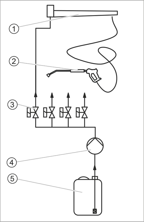
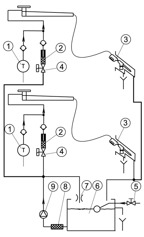
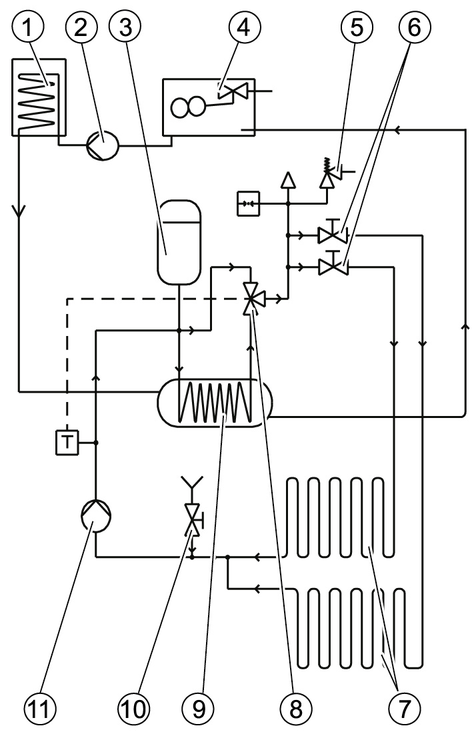
Washing stations 3 and 4 are not shown.
2-tool version (option)
A High pressure solenoid valve
B Foam solenoid valve
C High-pressure gun with spray lance
D Washing brush
* Only for SB MB standard
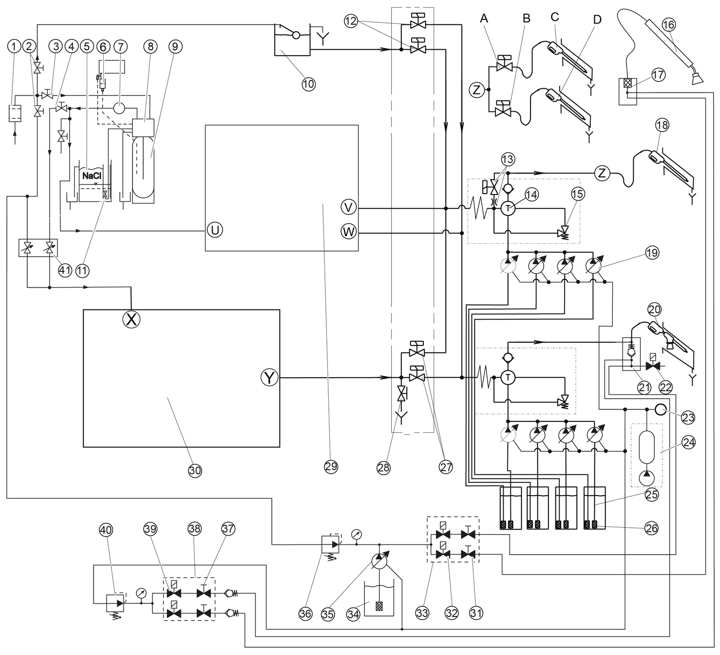
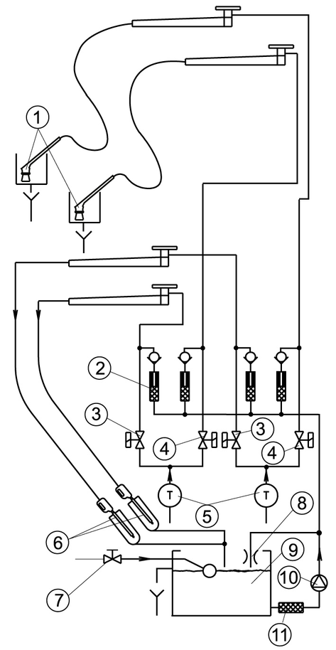
Washing stations 3 and 4 are not shown.
3-tool version
A Power foam lance solenoid valve
B High pressure solenoid valve
C Power foam lance
D High-pressure gun
* Only for SB MB standard
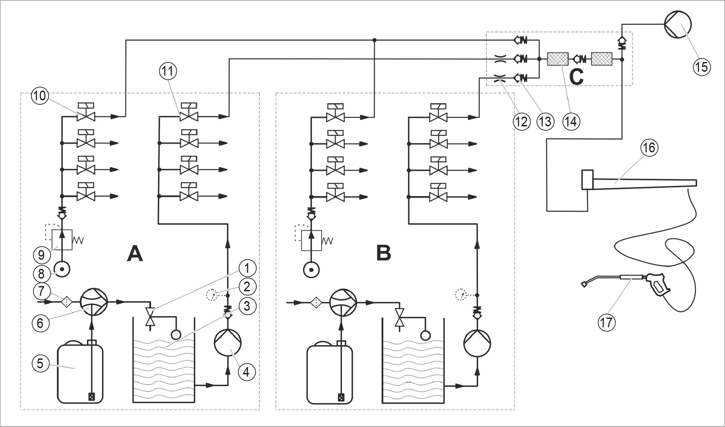
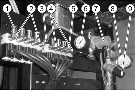
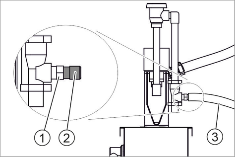
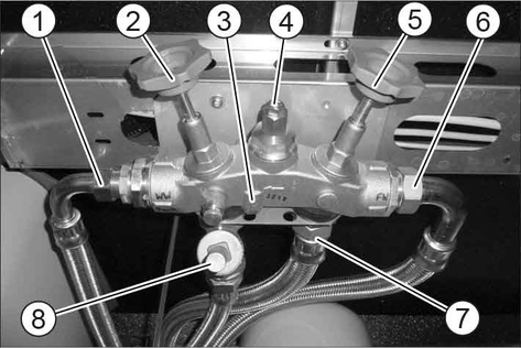
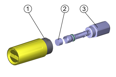
A Wheel cleaner
B Intensive foam
C Node piece

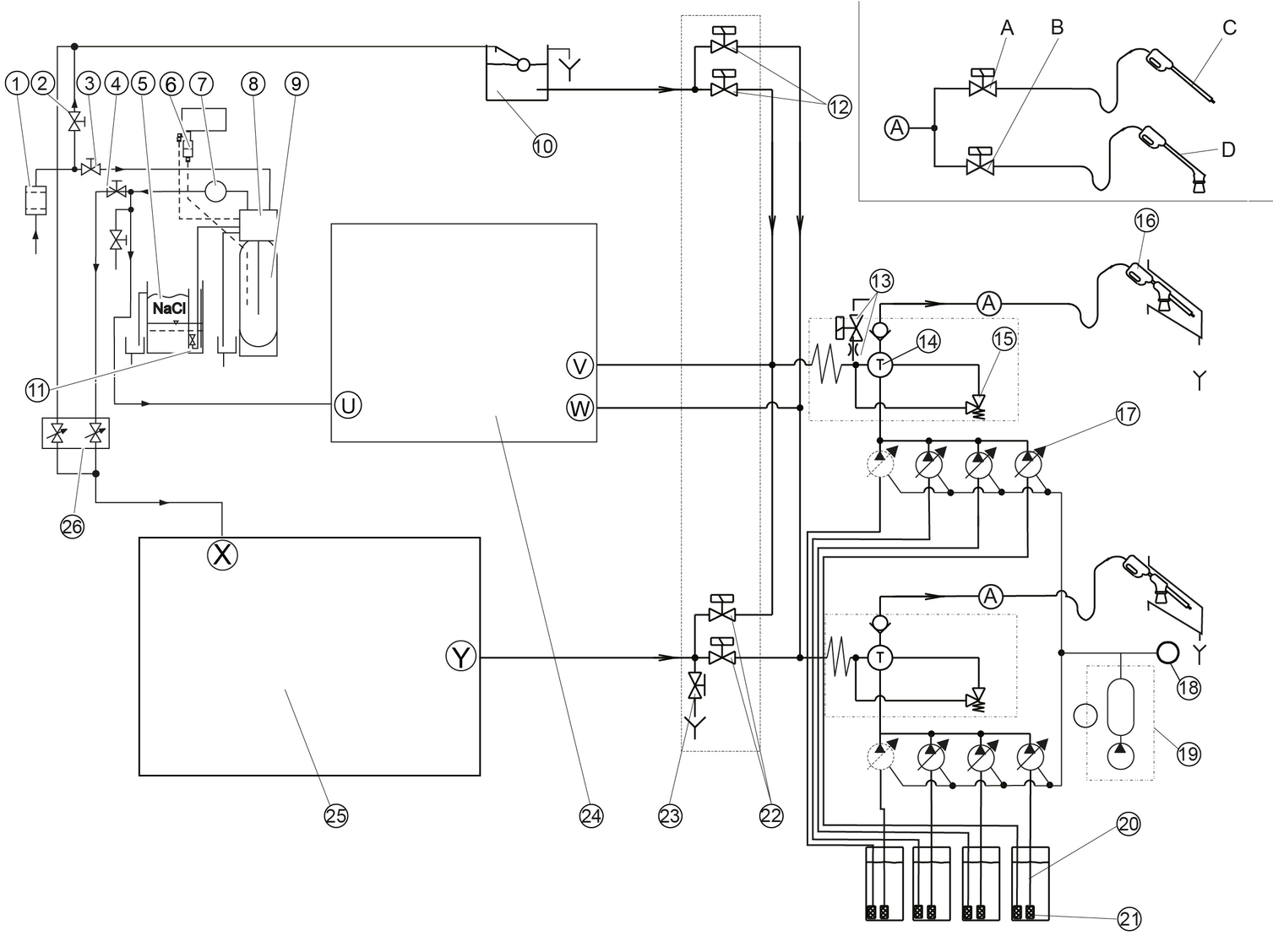
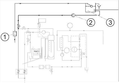
A 4. water type
B Fresh water
C Softened water, hot
D Permeate
E to the high pressure pump
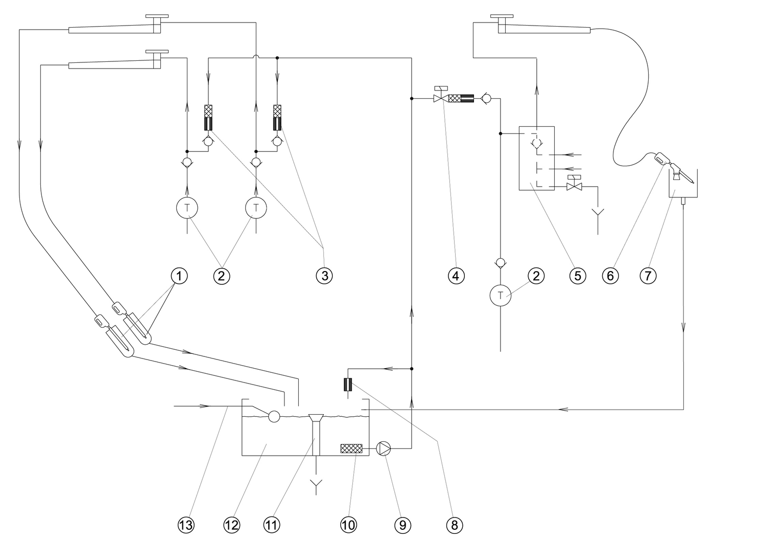
On the 2-tool version with dry foam, electrically heated foam hoses are used as frost protection.
The frost protection water is lost at washing station 3 and 4.
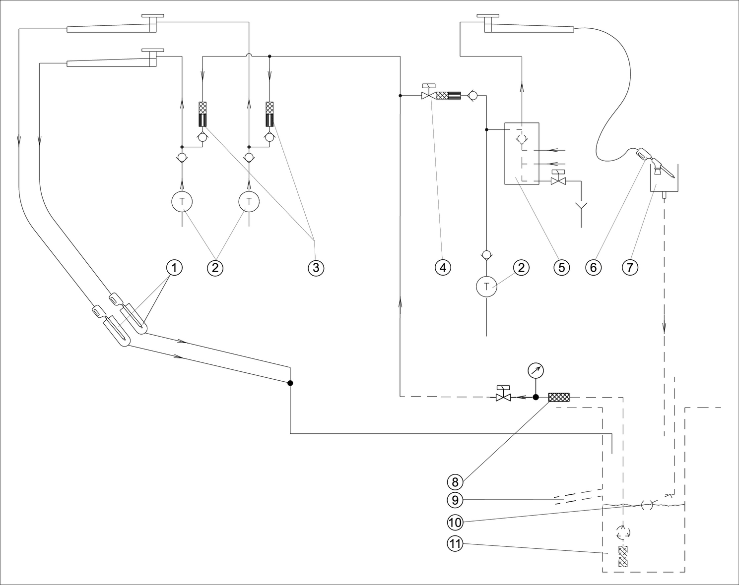
On the 2-tool version with dry foam, electrically heated foam hoses are used as frost protection.
Washing station 3 and 4 are not shown
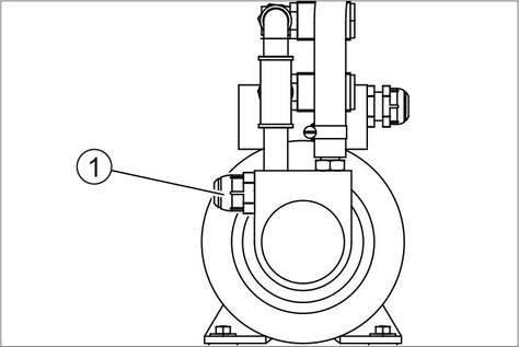
The pressure relief valve opens when the permissible operating pressure is exceeded, i.e. also when the lever of the high-pressure gun is released, and circulates the water. The high-pressure jet is immediately available again when the high-pressure gun is opened again.
The overflow valve is set and sealed at the factory. Setting must only be performed by Customer Service.
The safety valve protects the heating circuit of the washing station heater (option) against overpressure.
The thermostatic mixing valve regulates the flow temperature for the washing station heater (option) depending on the return temperature.
Only for devices with oil or gas burner.
If the burner does not ignite or if the flame goes out during operation, the flame monitor closes the fuel solenoid valve and switches off the burner fan.
Only for devices with oil or gas burner.
If the emission temperature rises above the permissible value, the emission thermostat switches off the burner and locks it.
Not for electrically heated devices without washing station heating.
If the water temperature in the hot water float tank drops due to the withdrawal of hot water and cold water flowing in, the temperature controller switches the hot water circulation pump on and off again when the maximum temperature is reached.
Only for devices with oil or gas burner.
The temperature limiter prevents steam from forming in the continuous flow boiler.
Only for devices with oil or gas burner.
The flow monitor switches the burner on once the hot water hot water circulation pump has started.
The water shortage safeguard shuts off the hot-water generator when the water level in the hot water float switch is too low.
Only for electrically heated devices.
Switches off the heating rod in case of overtemperature due to water shortage.
The motor circuit breaker interrupts the circuit when the motor is overloaded.
SB MB standard:
If the residual hardness of the softened water exceeds a limit value, the controller calculates the residual capacity of the base exchanger bottle.
The regeneration of the base exchanger bottle is started the following night at the latest.
SB MB comfort:
If the residual hardness of the softened water exceeds a limit value, the regeneration of the base exchanger bottle begins immediately.
If there is a water shortage, the system is stopped to prevent the RO pump from running dry.
Switches off the RO pump when the permeate buffer tank is full.
Switches on the pump RO to produce permeate.
Gives a signal to the system when the buffer tank permeate is empty.
Prevents externally supplied hot water above 60°C from being directed to the high-pressure pumps and damaging them.
In the event of a malfunction, the system switches to an alternative type of water (set by the service technician during commissioning).
Regular maintenance according to the following maintenance plan is fundamental for a safely operating system.
Use only original manufacturer spare parts or parts recommended by the original manufacturer, such as
Spare parts and wearing parts,
Accessories,
Operating materials,
Detergent.
Risk of injury
Danger of death from electric shock.
Switch off the device at the on-site main trigger and secure against being switched on again before working on the device.
Allow only qualified electricians to work on electrical components of the system.
Risk of injury
A high pressure water jet can escape from damaged parts and cause injuries.
Depressurise the system by turning the trigger to "0/OFF" and then open the high-pressure guns until the pressure has been released from the system.
Danger of burns
Some components of the system become hot during operation and can cause burns if touched.
Allow the system to cool down before touching the following components: Exhaust pipe and exhaust opening, burner with booster heater, cylinder head of the high-pressure pump, high-pressure hose.
Risk of damage
A high-pressure water jet can damage system components.
Do not clean the interior of the system with the high-pressure jet. When performing exterior cleaning, keep the high-pressure jet away from the upper section of the system (with coin slot, remaining value display and program switch).
Switch off the on-site main switch and secure it against being switched on again.
Disconnect the water supply.
Operator: Work labelled with "Operator" may only be performed by instructed persons capable of operating and maintaining high-pressure systems.
Customer Service: Work labelled with "Customer service" may only be performed by KÄRCHER customer service technicians or KÄRCHER-authorised technicians.
You can agree on regular safety inspections or close a maintenance contract with your dealer. Please seek advice on this.
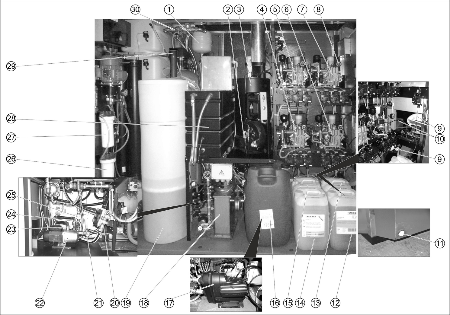
* Depending on the equipment of the system, the intensive foam assembly may also be fitted at these points.
The Maintenance Diagnostic menu shows the times until the next maintenance, system information, error messages and events.
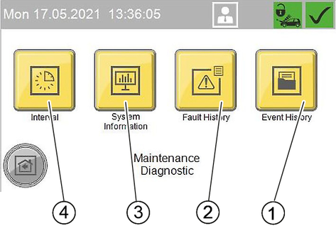
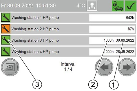
In the Interval menu, the time until the next maintenance is displayed for the individual system components.
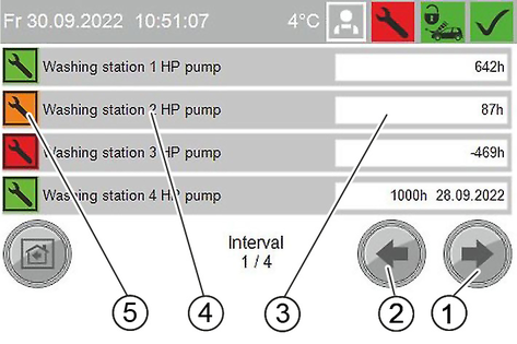
green: remaining operation duration more than 30% of the total time
orange: remaining operation duration less than 30% of the total time
red: Service counter expired, maintenance must be carried out
If a service counter has expired, the controller displays a maintenance request in the standard setting:
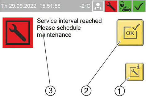
Reset service counter
The following service counters can be reset by the operator:
Replace the filter element WSO
Vacuum cleaner 1...6, filter 1
Vacuum cleaner 1...6, filter 2
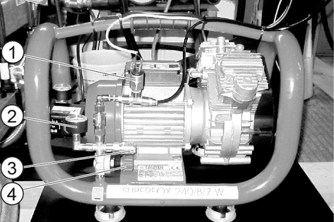
Drain the compressor
Check the frost protection
All remaining service counters can only be reset by Customer Service.
Press the "Reset service counter" button.
Confirm the reset with Yes.
Display after reset
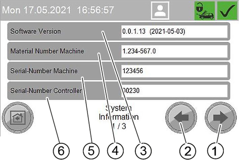
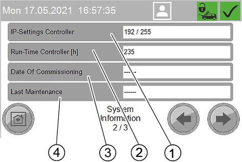
In the System Information menu, system data, settings of the control and operations data of the control are displayed.
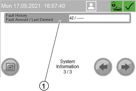
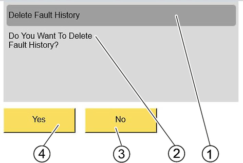
In the Fault History menu, the error messages since the last deletion of the fault memory are displayed.
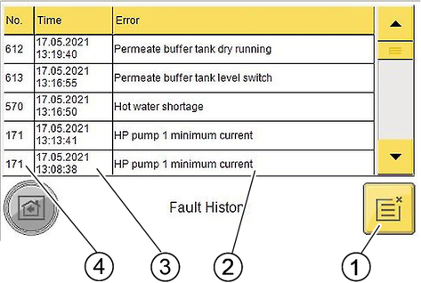
The Event History menu is structured in the same way as the Fault History menu.
Time & date | Activity | Performed | By whom |
|---|---|---|---|
annually before the beginning of the frost period | Clean the frost protection circuit |
| Operator/Customer Service |
Check the washing station heater |
| Operator/Customer Service | |
Check the outdoor thermostat | Check the function. | Operator | |
Check the recirculation fan | Check the function. | Operator | |
Check the hot air blower. | Are the controllers set correctly? (see section "Settings / Hot air blower"). | Operator | |
Check frost protection with water loss | Switch on the frost protection pump (see chapter "Manual interventions"). Check that at least 0.5 l/min of water comes out of each manual trigger gun, readjust the pressure reducer if necessary. | Operator | |
Check the emergency frost protection | Turn the main switch to position “0”. Check that at least 0.5 l/min of water comes out of each manual trigger gun, readjust the pressure reducer if necessary. | Operator | |
Clean the flow-through vessel | Recommendation: Schedule this semi-annual maintenance work before the start of the frost period. | Customer Service | |
Measure the burner | |||
Daily | Check the high-pressure hoses, Check the foam hoses (for 2-WZ version) | Examine the high-pressure hoses for mechanical damage such as abrasion damage, visible hose fabric, kinks and cracked rubber. Replace damage high-pressure hoses. | Operator |
Check the washing brushes. | Check the washing brushes for damage, soiling and wear. Replace bristles that are shorter than 30 mm. In winter at temperatures below –5 °C, check for ice formation and lock the foam wash if necessary. Replace the combination spray lance with a high-pressure spray lance for this. | Operator | |
Check the information notices at the washing station. | Check that the user information notices are present and legible. | Operator | |
Check the washing station lighting | Check the function of the washing station lighting, replace defective lamps. | Operator | |
Check the spray lances | Check for tightness, replace the O-ring if necessary. Nozzle protection and grip tube OK? Replace if necessary. | Operator | |
Check the high-pressure guns | Check for tightness, replace the O-ring if necessary. Is the high-pressure hose rotatable and the lever smooth-running? Lubricate if necessary (see section "Maintenance work"). | Operator | |
Check the tool storage trough | Check from the outside for foreign bodies and dirt. Remove coarse contamination. | Operator | |
Check the detergent filling level. | Check the filling level and top up if necessary. | Operator | |
Emptying the coin box | Open the coin acceptor door and empty the coin box. | Operator | |
daily at first, later according to experience | Check the fuel tank filling level | Is the heating oil supply sufficient until the next inspection? Take into account increased consumption due to frost protection devices. Lack of fuel leads to failure and damage to the system. | Operator |
Empty the compressor | Drain the condensation water from the compressor's pressure tank. | Operator | |
For systems with frost protection: Daily in the case of frost | Check the frost protection devices. | Are the hot air blowers in operation (also in the ABS fuel tank, option)? | Operator |
Clean the frost protection pump filter | Clean the filter and re-insert. | Operator | |
After 40 operating hours or weekly | Check the leak-tightness of the system | Check pump and line system for leaks. Contact Customer Service when oil is present under the high-pressure pump or when more than 3 drops of water per minute escape from the high-pressure pump during operation. | Operator |
Check the oil level | Milky oil indicates water in the oil. Contact customer service. | Operator | |
Check the oil level of the high-pressure pumps | The oil level must lie between the MIN and MAX marks, otherwise refill with oil. | Operator | |
Checking detergent filter | Visually check the high-pressure jet for the presence of detergent, clean detergent filter if necessary. | Operator | |
Check for correction function | Checking the functionality of all washing programs | Operator | |
Check the salt supply in the salt tank | Is the salt level above the water level? Top up the softening salt if necessary. | Operator | |
Check the residual hardness of the softened water | Remove water from the hot water float tank and determine the residual hardness with test set B (order no. 6.768-003). Target value: Less than 3 °dH. | Operator | |
Check residual chlorine content after active carbon filter | This test is only necessary if the chlorine content in the fresh water is above 0.3 mg/l. Take a water sample between the active carbon filter and the RO membrane. Determine the residual chlorine content. If the residual chlorine content of the water sample exceeds 0.1 mg/l, replace the active carbon filter. | Operator | |
Briefly switch on the washing station heater | Activate the frost protection pump as described for "Controller/menu Service". | Operator | |
Clean the outside of the housing (stainless steel and plastic) | Mix a 10% solution of the "Washing hall and tile cleaner RM 841" detergent, apply to the surfaces, allow to react for approx. 2 to 3 minutes, do not allow to dry. After the contact time, rinse thoroughly with the high-pressure jet. | Operator | |
Mix a 20% solution of "Washing Hall and Tile Cleaner RM 841" detergent, apply to the surface and allow to react for approx. 2 to 3 minutes. After the contact time, clean the surfaces with a damp pad or microfibre cloth and then rinse thoroughly with a high-pressure jet. If desired, the large surfaces can be wiped off with a rubber squeegee. | Operator | ||
Cleaning the splash guard tarpaulins | Mix a 10% solution of the "Washing hall and tile cleaner RM 841" detergent, apply to the surfaces, allow to react for approx. 2 to 3 minutes, do not allow to dry. After the contact time, rinse thoroughly with the high-pressure jet. ATTENTIONRisk of damage Solvents and detergents containing solvents can damage the splash guard tarpaulins. Do not clean the splash guard tarpaulins with solvents or detergents containing solvents. | Operator | |
Maintain the casing exterior (stainless steel) | Treat with stainless steel care product as required. | Operator | |
weekly during frost | Check the heating ABS fuel oil tank (option) | Below 3 °C, check whether the trace heating of the fuel oil line between the heating oil tank and SB MB is warm. | Operator |
Once, 1 month after initial startup | Changing the WSO fine filter | Shut off the fresh water inlet, unscrew the filter cup, replace the filter insert, refit the new filter insert and filter cup, open the fresh water inlet. | Operator |
After 80 operating hours or fortnightly | Clean and preserve the stainless steel parts of the housing. | Remove dirt residues and deposits. Preserve parts with stainless steel care oil. | Operator |
After 200 operating hours or monthly | Check the operating pressure of the high-pressure pumps | The pressure gauge must indicate 9...10 MPa (90...100 bar). Otherwise, rectify the fault according to the information in the section "Help with faults". | Operator |
Check the antifreeze water quantity | Target value: approx. 0.5 l/min per washing tool. Water volume greater: Replace the node piece in the high-pressure gun. WARNINGRisk of injury, risk of damage The high-pressure gun can move uncontrollably and cause injuries or damage if the frost protection water volume is too high. Be sure to replace the node piece in the high-pressure gun if the frost protection water quantity is too high. Water quantity smaller: Clean the frost protection pump filter, clean the sieve in the throttle, flush the pipe, check the direction of rotation of the pump. | Operator | |
Clean the detergent filter in the detergent container | Remove the filter and rinse thoroughly with clean water. | Operator | |
Cleaning the filter | Clean the filter for frost protection circuit water. | Operator | |
Clean the storage troughs | Clean the tool storage troughs. | Operator | |
Checking the salt tank | Check the water level (approx. 5...25 cm above the sieve plate). | Operator | |
Check for deposits, empty if necessary, clean, refill with softening salt and put back into operation. Danger of malfunctions. When topping up with softening salt, use only the softening salt in tablet form listed in the chapter 'Accessories'. | Operator | ||
Clean the burner |
| Operator | |
Lubricate the ceiling boom | Lubricate the grease nipple with a grease gun (grease 6.288-055.0). | Operator | |
Lubricate the door hinges. | Lubricate the hinges with grease (order no.: 6.288-072). | Operator | |
Preserve the locks of the doors | Spray care agent (order no.: 6.288-116) into the locks. | Operator | |
Quarter-yearly | Cleaning the coin slot | Open the coin acceptor door. Clean the coin slot (see section "Maintenance work"). | Operator |
Check the time setting | Check the time and date set on the controller and correct if necessary. | Operator | |
After 1000 operating hours or half-yearly | Check the pump heads. | Replace the valves completely if the valve discs are severely damaged. | Customer Service |
Replace the oil in the high-pressure pump. | See Maintenance work. | Operator | |
Clean the flow-through vessel | Clean soot and scale from the heating coil. | Customer Service | |
Measure the burner | Measure the exhaust gas values, clean and adjust the burner if necessary. | Customer Service | |
Changing the WSO fine filter | Shut off the fresh water inlet, unscrew the filter cup, replace the filter insert, refit the new filter insert and filter cup, open the fresh water inlet. | Operator | |
Annually before the frost period | Cleaning the filter in the Power foam nozzle (option) | See "Cleaning the frost protection/Power foam nozzle". Determine the following cleaning intervals according to experience. | Operator |
Annually | Safety check | Safety check according to the directives for liquid jet cleaners/accident prevention guideline. | Customer Service |
System maintenance | Maintenance contract with replacement of all wear parts. | Customer Service | |
Check the temperature controller | Check the function of both temperature controllers. | Customer Service | |
Changing the filter inlay of the active carbon filter WSO | Close the stop valve for fresh water (provided by the customer), unscrew and rinse out the filter cup, replace the filter inlay with a new one, refit the filter inlay and the filter cup, open the stop valve for fresh water and start up the system. | Operator/Customer Service | |
Check the RO pump | Inform Customer Service. Check characteristic curve (flow rate and pressure). | Customer Service | |
Gas burner maintenance | Have maintenance work carried out by the burner manufacturer's Customer Service. | ||
Every 5 years or as required | Cleaning the fuel tank | Pump out the remaining fuel. Empty the sediment and dispose of it. Clean the inside of the tank. | Tank cleaning service |
Hold the condensate drain valve over a shaft or collecting container.
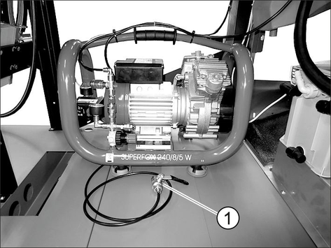
Open the condensate drain valve and drain the condensate.
Close the condensate drain valve.
Unscrew the spray lance.
Unscrew the 6 screws.
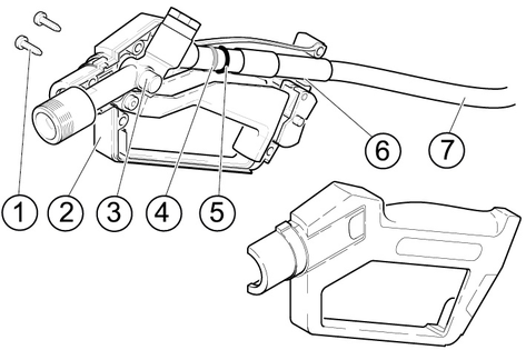
Remove the handle bowl half.
Fill the chamber for the needle bearing in the handle bowl half with grease.
Grease the needle bearing and the O-ring.
Grease the pipe / handle bowl contact surface.
Screw the handle bowl halves back together.
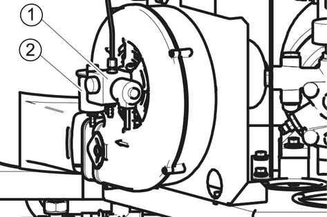
Release the fuel line.
Pull the light sensor sideways out of the holder.
Unscrew the 3 screws.
Remove the cover with the holder for the light sensor.
Remove the baffle plate from the nozzle holder.
Clean the sight glass.
Reassemble the parts in reverse order.
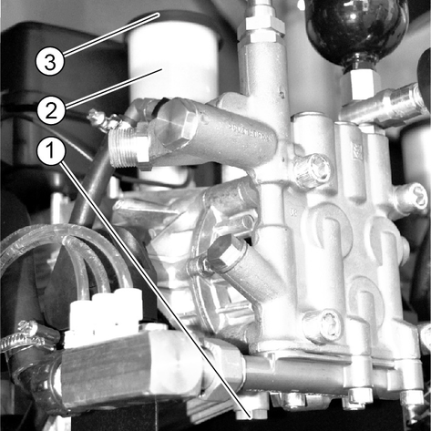
Shut off the oil supply line.
Unscrew the filter casing.
Clean the filter with compressed air.
Install the fuse holder in the reverse order.
Open the oil supply line.
Danger of burns
The high-pressure pump and the engine oil are hot and cause burns if touched.
Allow the high-pressure pump to cool down for 15 minutes before changing the oil.
Old oil may only be disposed of at designated collection points. Please dispose of any old oil at these locations. Polluting the environment with old oil is punishable by law.
Place a suitable oil collection container under the oil drain screw.
Remove the oil tank cap.
Unscrew the oil drain screw and catch the escaping oil.
Replace the sealing ring and screw in and tighten the oil drain screw.
Slowly fill with new oil until the "MAX" marking on the oil tank.
Fit the oil reservoir cap.
Dispose of the old oil in an environmentally friendly manner or hand it over to an authorised collection point.
Open the device door.
Open the coin acceptor.
Clean the coin track with a damp cloth with washing-up liquid.
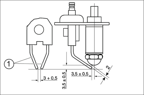
The correct setting of the ignition electrodes is important for the function of the burner. The setting dimensions are shown in the drawing below.
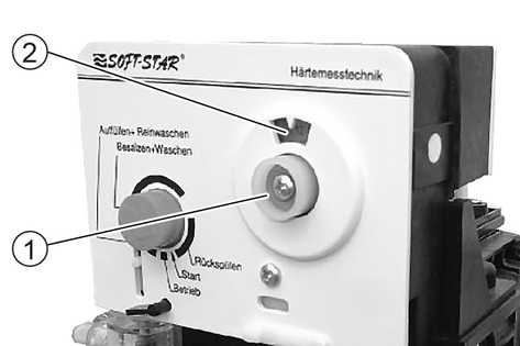
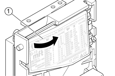
Start the regeneration via the controller (see "Controller/Service menu").
Press in the programme button and turn the camshaft anticlockwise until the arrow on the programme button points to "Salting + washing".
Risk of injury
Danger of death from electric shock.
Switch off the device at the on-site main trigger and secure against being switched on again before working on the device.
Allow only qualified electricians to work on electrical components of the system.
Risk of injury
A high pressure water jet can escape from damaged parts and cause injuries.
Depressurise the system by turning the trigger to "0/OFF" and then open the high-pressure guns until the pressure has been released from the system.
Danger of burns
Some components of the system become hot during operation and can cause burns if touched.
Allow the system to cool down before touching the following components: Exhaust pipe and exhaust opening, burner with booster heater, cylinder head of the high-pressure pump, high-pressure hose.
Switch off the on-site main switch and secure it against being switched on again.
Disconnect the water supply.
Operator: Work labelled with "Operator" may only be performed by instructed persons capable of operating and maintaining high-pressure systems.
Qualified electrician: Work labelled with "Electrician" may only be performed by qualified electricians.
Customer Service: Work labelled with "Customer service" may only be performed by KÄRCHER customer service technicians or KÄRCHER-authorised technicians.
Customer Service of the burner manufacturer: Faults on the gas burner may only be repaired by the burner manufacturer's Customer Service.
If critical errors, fault messages or events are present, the start screen automatically changes to the message view after approx. 1 minute.
A pending message is indicated on the controller by an Attention symbol in the upper right corner.
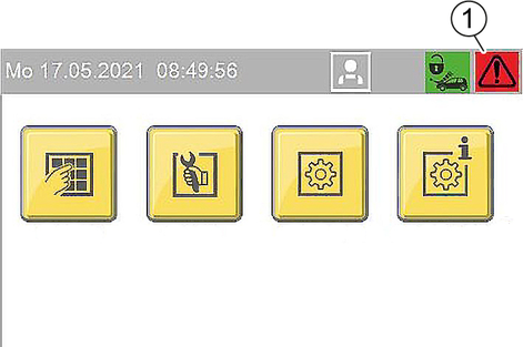
Message displays
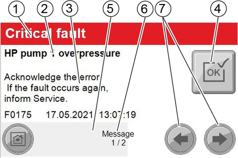
red: critical error. Depending on the error, the system reacts as follows:
The system goes into emergency operation.
One or more washing stations are locked out.
The entire system is locked out.
Yellow: Fault; the system can continue operating
green: Event; information for the operator
If the button is greyed out, the error is still present and cannot be acknowledged.
If the button has a yellow background, the fault has been rectified and the error can be acknowledged.
The view switches to the next screen automatically after approx. 2-3 seconds. The progress bar has then finished.
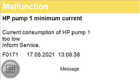
Example fault display
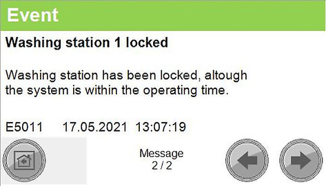
Example event display
Only faults that can be rectified by the operator are listed here.
In case of faults that are not described here: Acknowledge the message. If the fault occurs again, inform Service.
Error number | Cause | Rectification |
|---|---|---|
F0103 | Malfunction oil separator / recycling | Check or empty external oil separator / Check recycling system |
F0105 | Motor circuit breaker of high-pressure pumps has tripped | Reset motor circuit breaker. If the fault occurs again, inform Service |
F0107 | Air pressure switch signals no pressure | Check compressor and compressed air lines |
F0113 | Motor circuit breaker / automatic circuit breaker frost protection | Reset motor circuit breaker or automatic circuit breaker. If the fault occurs again, inform Service |
F0114 | Hot water temperature too low | Washing station heater has been turned off, Check hot water generator and hot water circuit |
F0115 | Motor circuit breaker of foam hose heater | Reset motor circuit breaker. If the fault occurs again, inform Service |
F0116 | Motor circuit breaker of stations | Reset motor circuit breaker. If the fault occurs again, inform Service |
F00170 | HP pump 1 overcurrent | Current consumption of HP pump too high Acknowledge fault. If the fault occurs again, inform Service. |
F00174 | HP pump winding protect.contact 1 | Acknowledge the error. If the fault occurs again, inform Service. |
F00176 | HP pump 1 oil level too low | Refill oil. Acknowledge malfunction |
F0191 | Coin signal remote control 1 | At mechanical coin acceptor check the microswitch |
F0210 | HP pump 2 overcurrent | Current consumption of HP pump too high Acknowledge fault. If the fault occurs again, inform Service. |
F0214 | HP pump winding protect.contact 2 | Acknowledge the error. If the fault occurs again, inform Service. |
F0216 | HP pump 2 oil level too low | Refill oil. Acknowledge malfunction |
F0231 | Coin signal remote control 2 | At mechanical coin acceptor check the microswitch |
F0250 | HP pump 3 overcurrent | Current consumption of HP pump too high Acknowledge fault. If the fault occurs again, inform Service. |
F0254 | HP pump winding protect.contact 3 | Acknowledge the error. If the fault occurs again, inform Service. |
F0256 | HP pump 3 oil level too low | Refill oil. Acknowledge malfunction |
F0271 | Coin signal remote control 3 | At mechanical coin acceptor check the microswitch |
F0290 | HP pump 4 overcurrent | Current consumption of HP pump too high Acknowledge fault. If the fault occurs again, inform Service. |
F0294 | HP pump winding protect.contact 4 | Acknowledge the error. If the fault occurs again, inform Service. |
F0296 | HP pump 4 oil level too low | Refill oil. Acknowledge malfunction |
F0311 | Coin signal remote control 4 | At mechanical coin acceptor check the microswitch |
F0570 | Hot water shortage | Check the hot water supply |
F0571 | Hot water overtemperature | Acknowledge the error. If the fault occurs again, inform Service. |
F0574 | Oil stoker malfunction | Press the Reset button on the oil-firing unit |
F0575 | Exh. gas thermostat triggered | Press the Reset button on the exhaust gas thermostat |
F0576 | No flow detected by flow monitor | Acknowledge the error. If the fault occurs again, inform Service. |
F0577 | Flow monitor is defective | Acknowledge the error. If the fault occurs again, inform Service. |
F0578 | Automatic hot water circuit-breaker | Reset automatic circuit-breaker. If the fault occurs again, inform Service |
F5081 | Hot water circ. pump motor circuit breaker | Reset motor circuit breaker. If the fault occurs again, inform Service |
F0584 | Washing station heater circ. pump motor circuit breaker | Reset motor circuit breaker. If the fault occurs again, inform Service |
F0586 | On-site heating | Check on-site heating system |
F0587 | Water temperature above 60 °C. | Water temperature of external hot water supply above 60 °C. Reduce the water supply temperature. |
F0610 | Softener bottle regeneration has failed. | Hardness sensor indicates hard water after regeneration. Refill salt, acknowledge fault |
F0612 | Osmosis tank running dry | Have the tank filled up to the empty osmosis tank level switch (maximum switch-on delay of 15 minutes) |
F0613 | Osmosis tank level switch | Empty and full osmosis tank level switches switch simultaneously.. Check level switch. |
F0614 | Osmosis tank level switch | Bottom and full osmosis tank level switches switch simultaneously. Check level switch. |
F0615 | Water softening no water pressure | Check the water supply |
F0617 | On-site water softening and osmosis system | Check on-site water softening and osmosis system |
F0650 | Vacuum cleaner 1 / button 1 jammed | Start button/vacuum cleaner station selection button is jammed |
F0651 | Vacuum cleaner 1 / button 2 jammed | Start button/vacuum cleaner station selection button is jammed |
Ff0660 | Vacuum cleaner 2 / button 1 jammed | Start button/vacuum cleaner station selection button is jammed |
F0661 | Vacuum cleaner 2 / button 2 jammed | Start button/vacuum cleaner station selection button is jammed |
F0670 | Vacuum cleaner 3 / button 1 jammed | Start button/vacuum cleaner station selection button is jammed |
F0671 | Vacuum cleaner 3 / button 2 jammed | Start button/vacuum cleaner station selection button is jammed |
F680 | Vacuum cleaner 4 / button 1 jammed | Start button/vacuum cleaner station selection button is jammed |
F0681 | Vacuum cleaner 4 / button 2 jammed | Start button/vacuum cleaner station selection button is jammed |
F0690 | Vacuum cleaner 5 / button 1 jammed | Start button/vacuum cleaner station selection button is jammed |
F0691 | Vacuum cleaner 5 / button 2 jammed | Start button/vacuum cleaner station selection button is jammed |
F0700 | Vacuum cleaner 6 / button 1 jammed | Start button/vacuum cleaner station selection button is jammed |
F0701 | Vacuum cleaner 6 / button 2 jammed | Start button/vacuum cleaner station selection button is jammed |
F0720 | Wheel cleaner pump overcurrent | Current consumption of pump too high. Acknowledge fault. If the fault occurs again, inform Service. |
F0740 | Micro-emulsion pump overcurrent | Current consumption of pump too high. Acknowledge fault. If the fault occurs again, inform Service. |
F0750 | Intensive foam pump overcurrent | Current consumption of pump too high. Acknowledge fault. If the fault occurs again, inform Service. |
Malfunction | Possible cause | Rectification | By whom |
|---|---|---|---|
Water shortage in the hot water float tank | Water inlet blocked | Open the stop valve for fresh water. | Operator |
Fine filter of fresh water in water treatment is contaminated | Clean or replace the filter inlay. | Operator | |
Float valve in the hot water float tank does not open | Check the float valve, repair if necessary. | Operator | |
Water shortage safeguard in the hot water float tank is stuck or defective | Check the water shortage safeguard, replace if necessary. | Operator | |
Hose line burst or loosened | Check the hose lines, replace if necessary. | Operator | |
Pump disconnection from mains (optional) not working | Check the voltage supply. | Customer Service | |
Check the pump. | Customer Service | ||
Water temperature too low / too high | Thermostat defective | Check the thermostat, replace if necessary. | Customer Service |
The hot-water generator does not start or stops heating | Flow monitor defective (not with electrically heated device) | Check the flow monitor, clean it, replace it if necessary. | Customer Service |
Washing water circuit is calcified | Check the water treatment, descale the circuit. | Customer Service | |
Air in the hot water circulation pump | Vent the pump at the venting screw. | Operator | |
Rotation direction of the hot water circulation pump is wrong | Check the rotation direction, change if necessary. | Customer Service | |
Thermostat defective | Check the thermostat, replace if necessary. | Customer Service | |
Protection for hot water circulation pump defective | Check the protection, replace if necessary. | Customer Service | |
Motor protection switch for hot water circulation pump has tripped because the circulation pump is blocked or the pump is defective | Check the circulation pump, repair or replace if necessary.Reset the motor protection switch. | Customer Service |
Malfunction | Possible cause | Rectification | By whom |
|---|---|---|---|
Circulation pump for washing station heater is out of operation | Temperature in the hot water tank below 10 °C (malfunction indicator "F0144"). | Locate and rectify the fault in the hot water circuit. | Operator/Customer Service |
Malfunction | Possible cause | Rectification | By whom |
|---|---|---|---|
Oil firing malfunction (automatic oil firing unit) in the electrical box of the burner controller was triggered) | No ignition spark present (visible through the sight glass in the burner cover) | Check electrode setting, ignition transformer and ignition cable. Clean electrodes, replace defective parts. Then press the release button of the automatic oil firing unit. | Customer Service |
Sight glass for flame monitoring is dirty | Clean the sight glass for flame monitoring (see section "Maintenance work"). Then press the release button of the automatic oil firing unit. | Operator | |
Light sensor for flame monitoring is not in holder or defective | Reattach or replace the light sensor. Then press the release button of the automatic oil firing unit. | Operator, Customer Service | |
Fuel oil level too low | Refill the fuel tank. Then press the release button of the automatic oil firing unit. | Operator | |
No flame due to a shortage of fuel | Clean the fuel filter on the fuel pump. Then press the release button of the automatic oil firing unit. | Operator | |
Clean the fuel nozzle and replace if necessary. Then press the release button of the automatic oil firing unit. | Operator | ||
Check the fuel solenoid valve, the fuel pump and the coupling. | Customer Service | ||
No flame due to a shortage of air | Check the collar on the blower for damage and tight fit of the straps. Then press the release button of the automatic oil firing unit. | Operator | |
The blower is defective, replace it. Then press the release button of the automatic oil firing unit. | Customer Service | ||
Strong smoke development during start-up and operation | Ignition electrode lies in the fuel jet | Check and correct the electrode setting. | Operator, Customer Service |
Fuel pressure incorrectly set (see section "Technical data") | Check the fuel pressure, set it again if necessary. | Customer Service | |
Heating coil heavily sooted | Dismantle the boiler and clean the heating coil. | Customer Service | |
Exhaust gas thermostat (S5) was triggered | Washing water circuit is calcified | Check the water treatment, descale the hot water circuit. Then press the exhaust gas thermostat release button. | Customer Service |
Heating coil heavily sooted | Dismantle the boiler and clean the heating coil. Then press the exhaust gas thermostat release button. | Customer Service | |
Burner is incorrectly set | Correct the burner setting. Then press the exhaust gas thermostat release button. | Customer Service |
Malfunctions on the gas burner may only be repaired by authorised specialist personnel of the burner manufacturer.
Malfunction | Possible cause | Rectification | By whom |
|---|---|---|---|
All coin acceptors reject all coins. | Main switch switched off. | Turn the main switch to "1". | Operator |
Time or operating times incorrectly set. Night-time operation lock active. | Check the settings at the controller. | Operator | |
Water shortage | Check the water supply. | Operator | |
The motor circuit breaker of the high-pressure pump has triggered. | Reset the motor circuit breaker. Search for the cause if this occurs repeatedly. | Operator | |
A single coin acceptor rejects all coins. | Coin acceptor dirty. | Clean the coin slot (see section "Maintenance work"). | Operator |
Overcurrent at the high-pressure pump. | Acknowledge the error at the controller. | Operator |
Malfunction | Possible cause | Rectification | By whom |
|---|---|---|---|
Uneven water jet on the high-pressure gun | High-pressure nozzle clogged | Replace the high-pressure nozzle. | Operator |
Water supply volume too low | Check the water supply volume (see "Technical data"). | Operator | |
Suction hose kinked | Check the suction hose. | Operator | |
Reduced pressure at the high-pressure pump | High-pressure nozzle worn out | Replace the high-pressure nozzle. | Operator |
Incorrect high-pressure nozzle installed | Replace the high-pressure nozzle (for size, see "Technical data"). | Operator | |
Water supply volume too low | Check the water supply volume (see "Technical data"). | Operator | |
Flush the solenoid valve and check the solenoid valve water quality. Check the float valve. | Customer Service | ||
High-pressure pump does not reach pressure | High-pressure pump sucking air from an empty detergent tank | Refill with detergent. Vent the suction line (if necessary, briefly squeeze the suction hose to the pump several times during operation to accelerate the venting process). | Operator |
High-pressure line to washing station leaking | Check the high-pressure line, replace if necessary. | Operator, Customer Service | |
Pressure relief valve incorrectly adjusted or leaking | Check the pressure relief valve, repair. | Customer Service | |
High-pressure pump knocking, pressure gauge fluctuates greatly | High-pressure pump sucking air | Check the water and detergent suction lines for leaks. | Operator |
Is the detergent container empty? (see above). | Operator | ||
Vibration damper defective | Replace the vibration damper. | Operator | |
Valve in the pump head defective or dirty | Replace defective valves. | Customer Service |
Malfunction | Possible cause | Rectification | By whom |
|---|---|---|---|
Insufficient or no detergent delivery | Filter or hose clogged | Clean the filter or the hose. | Operator |
Detergent hose leaking | Replace the hose. | Operator | |
Dosing pump incorrectly adjusted or defective | Check the dosing pump setting. | Operator | |
Check the functionality of the dosing pump. | Customer Service | ||
Condensation water in the dosing pump. | Drain the condensation water from the compressor pressure tank. | Operator |
Malfunction | Possible cause | Rectification | By whom |
|---|---|---|---|
Insufficient or no water/detergent delivery | The sieve in the water input is contaminated | Clean the sieve. | Operator |
Nozzle insert in injector is clogged | Clean the nozzle insert. | Operator | |
Throttle blocked in node piece | Clean the parts. | Operator | |
Foamer clogged in the node piece | Blow out the node piece with compressed air or replace the foamers. | Operator, Customer Service |
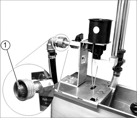
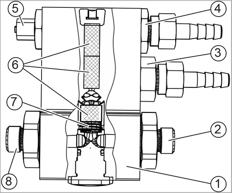
Malfunction | Possible cause | Rectification | By whom |
|---|---|---|---|
Compressor switches on and off frequently. | Condensation water in the pressure tank is too high. | Drain the condensation water from the compressor pressure tank. | Operator, Customer Service |
Malfunction | Possible cause | Rectification | By whom |
|---|---|---|---|
Foam quality is poor, foam too dry or too wet | Detergent container empty | Replace the container. | Operator |
Suction filter dosing pump is clogged | Rinse the filter with warm water. | Operator | |
Water supply is too low | Restore the water supply, check the setting of the foam station pressure reducer (0.25 MPa (2.5 bar)). | Operator | |
Compressor does not supply air | Check the compressor. Drain the condensation water from the compressor pressure tank. | Customer Service | |
Compressor is overheated | After cooling down, the compressor automatically starts up again. | Operator | |
Pressure reducer of foam station is contaminated | Clean the pressure reducer. | Operator | |
Solenoid valve for water/chemistry does not open | Check voltage with a magnetic field tester, clean the solenoid valve, replace if necessary | Operator, Customer Service | |
The setting of the dosing valves for water/chemistry or air is incorrect | Set to the standard setting (see chapter Operation and settings). | Customer Service | |
Incorrect detergent, detergent contaminated or old | Change the detergent. | Operator |
Malfunction | Possible cause | Rectification | By whom |
|---|---|---|---|
Base exchanger does not regenerate | No power supply. | Check the power supply (fuse, plug, switch). | Operator, Customer Service |
Hardness sensor is defective | Check the hardness sensor, replace if necessary. | Customer Service | |
Base exchanger regenerates during operating time | Clock was adjusted by power failure (option, only with WAT-S 202) | Reset the time (see "Settings/Setting the WAT-S 202 base autoexchanger") | Operator |
Water remains hard after regeneration | Salt tank is empty. | Refill softening salt, wait for brine formation (approx. 2 hours), start a manual regeneration. Never allow the salt level to fall below the water level in the salt tank. | Operator |
Injector filter is clogged | Clean the injector filter. | Customer Service | |
Water inflow to the salt tank is insufficient | Check the brine filling time, clean the brine filling orifice if necessary. | Customer Service | |
Riser pipe is leaking | Check the riser pipe and the pilot pipe. | Customer Service | |
Salt consumption is too high | Too much water in the salt tank | Check the salt consumption and salt quantity setting. | Customer Service |
Incorrect salt quantity setting | |||
Pressure loss | Deposits in the water supply | Clean the water supply. | Customer Service |
Deposits in the base exchanger | Clean the valve and resin board. | Customer Service | |
Too much water in the salt tank | Rinsing screen is blocked | Clean the rinsing screen. | Customer Service |
Injector is clogged | Clean the injector and filter. | Customer Service | |
Foreign body in the brine valve | Clean the brine valve, change the valve seat. | Customer Service | |
Power failure during brine filling | Check the power supply. | Customer Service | |
Brine is not sucked in | Water inlet pressure too low. | Increase the water inlet pressure to at least 0.3 MPa (3 bar). | Operator |
Rinsing screen is blocked | Clean the rinsing screen. | Customer Service | |
Injector is clogged | Clean the injector and filter. | Customer Service | |
Leak in the valve interior | Replace the valve flaps. | Customer Service | |
Water is constantly in the drain, even after regeneration | Valve does not perform cycles correctly | Check the timer programme, replace the valve control if necessary. | Customer Service |
Foreign body in the valve | Remove the valve control, remove the foreign body, check the valve in all positions. | Customer Service | |
RO pump does not start | Permeate buffer tank is full | Wait until permeate is used up. | Operator |
The “buffer tank full” level switch is faulty | Check the level switch. | Customer Service | |
Start-up time of the controller is not yet finished | Wait. | Operator | |
Pressure switch for water shortage was triggered | Fine filter or active carbon filter is contaminated. Check both filters, replace the filter inlay if necessary. | Operator | |
Pressure switch has a water shortage fault | Check the pressure switch, replace if necessary. | Customer Service | |
Base exchanger regeneration is running | Wait for the end of the regeneration. | Operator | |
No softened water comes from the base exchanger | Check the base exchanger. | Operator, Customer Service | |
Pump disconnection from mains (optional) not working | Check the voltage supply. Check the pump. | Customer Service | |
RO pump only starts after several flushing cycles | Water mains pressure too low | Check the water mains pressure, if necessary open the supply valve completely. | Operator |
Fine filter or active carbon filter is contaminated | Check both filters, replace the filter inlay if necessary. | Operator | |
Permeate output is too low, buffer tank permeate is often empty | Water supply temperature is too low | Measure the temperature of the softened water and compare it with the technical data. | Operator |
Operating pressure is too low | Readjust the operating pressure. | Customer Service | |
Lime or mineral deposits on the filter surface of the RO membrane | Descale the membrane, replace if necessary. | Customer Service | |
The buffer tank “full” level switch is faulty | Check the level switch. | Customer Service | |
Bacteria or algae deposits on the filter surface of the RO membrane | Rinse the membrane for a long time, replace if necessary. Note in the future: Water in drinking water quality, avoid long downtimes. | Customer Service | |
Stains on the car paint with Top-Care (permeate insufficiently demineralised) | Mineral content of the softened water is too high | Check the conductivity of the softened water. | Customer Service |
Break in the RO membrane, defective sealing | Replace seal or membrane. Check the conductivity. | Customer Service | |
Mixing permeate and softened water | Compare the conductivity of permeate from the spray lance and water from the permeate buffer tank. | Customer Service |
Malfunction | Possible cause | Rectification | By whom |
|---|---|---|---|
Hot air blower not operating | Hot air blower incorrectly adjusted. | Check the settings of the hot air blower (see "Settings/Hot air blower"). | Operator |
Hot air blower is defective | Replace the hot air blower. | Customer Service | |
Frost protection not operating | Voltage supply has been interrupted. | Check the power supply and ensure availability. | Operator |
Outdoor temperature sensor is incorrectly mounted | See section "Installing the system". | Customer Service | |
Spray lance, high-pressure gun and high-pressure hose are frozen | Sieve with throttle is clogged (marked red) | Open the screw connection. Clean the sieve. Check the throttle bore for free passage. | Operator |
Frost protection pump filter is clogged | Clean the filter and insert it again. | Operator | |
Washing station heater does not work during frost | Outdoor temperature sensor is incorrectly mounted | See section "Installing the system". | Customer Service |
Heat exchanger or circulation pump is defective | Check the heat exchanger, pump and pipe system, repair if necessary. | Customer Service | |
Burner malfunction | Remedy the burner malfunction. | Operator | |
The washing station heater circulation pump motor circuit breaker was triggered | Reset the motor circuit breaker, determine cause if repeated. | Operator, Customer Service |
SB MB | 5/10-2 | 9/12-2 | 5/10-3 | 9/12-3 | 5/10-4 | 9/12-4 | |||||||
|---|---|---|---|---|---|---|---|---|---|---|---|---|---|
High-pressure module 608, 608fl | Piece | 2 | 1 | - | 3 | 2 | 1 | - | 4 | 3 | 2 | 1 | - |
High pressure module 908 | Piece | - | 2 | 2 | - | 1 | 2 | 3 | - | 1 | 2 | 3 | 4 |
Electrical connection | |||||||||||||
Voltage | V/~/Hz | 400/3~/50 | |||||||||||
Maximum permissible mains grid impedance | Ohm | 0.301 + j 0.188 | |||||||||||
Protection class version CAB (version SKID) | IP X5 (IP X1) | ||||||||||||
Connection output, oil/gas heated | kW | 10 | 17 | 13 | 13 | 14 | 16 | 17 | 16 | 17 | 19 | 20 | 22 |
Connection output, electrically heated 24 kW | kW | 36 | - | 39 | - | - | - | - | - | - | - | - | - |
Connection output, electrically heated 48 kW | kW | 57 | 59 | 60 | 60 | 62 | 63 | 65 | 63 | 64 | 66 | 68 | 69 |
Pre-fuse, oil/gas heated | A | 35 | 35 | 35 | 35 | 35 | 50 | 50 | 50 | 50 | 50 | 50 | 50 |
Pre-fuse, electrically heated 24 kW | A | 80 | - | 80 | - | - | - | - | - | - | - | - | - |
Pre-fuse, electrically heated 48 kW | A | 100 | 100 | 100 | 100 | 125 | 125 | 125 | 125 | 125 | 125 | 125 | 125 |
Connection output with frost protection, oil/gas heated | kW | 15 | 17 | 18 | 18 | 20 | 21 | 23 | 21 | 22 | 24 | 25 | 27 |
Connection output with frost protection, electrically heated 24 kW | kW | 39 | - | 42 | - | - | - | - | - | - | - | - | - |
Connection output with frost protection, electrically heated 48 kW | kW | 63 | 64 | 66 | 66 | 67 | 69 | 70 | 68 | 70 | 71 | 73 | 74 |
Pre-fuse with frost protection, oil/gas heated | 35 | 35 | 50 | 50 | 50 | 50 | 50 | 50 | 50 | 63 | 63 | 63 | |
Pre-fuse with frost protection, electrically heated 24 kW | 80 | - | 80 | - | - | - | - | - | - | - | - | - | |
Pre-fuse with frost protection, electrically heated 48 kW | 100 | 125 | 125 | 125 | 125 | 125 | 125 | 125 | 125 | 125 | 125 | 125 | |
Water connection | |||||||||||||
Water pressure, dynamic | MPa (bar) | 0.3...0.6 (3...6) | |||||||||||
Nominal width (DN) | mm | 25 | |||||||||||
Fresh water input amount/4. water type | m3/h | 1.7 | 2.0 | 2.3 | 2.2 | 2.6 | 2.9 | 3.3 | 2.7 | 3.2 | 3.5 | 3.9 | 4.2 |
Input amount warm water by customer 2 | m3/h | 1.2 | 1.5 | 1.8 | 1.8 | 2.1 | 2.4 | 2.7 | 2.4 | 2.7 | 3.0 | 3.3 | 3.6 |
Tank content | |||||||||||||
Hot water float tank | l | 80 | |||||||||||
Cold water float tank | l | 2.5 | 2 x 2.5 | ||||||||||
Performance data | |||||||||||||
Working pressure with supplied nozzle 1 | MPa (bar) | approx. 10 (100) / approx. 10 (100) / approx. 12 (120) | |||||||||||
Working pressure for program hot wax, foam wash 1 | MPa (bar) | approx. 3 (30) / approx. 10 (100) / approx. 4.5 (45) | |||||||||||
Nozzle size 1 | 5004, 2504 / 5004, 2504 / 5006, 2507 | ||||||||||||
Recoil force of the trigger gun with supplied nozzle 1 | N | 17 / 17 /29 | |||||||||||
Water consumption per washing station 1 | l/h (l/min) | approx. 500 (8.3) / approx. 500 (8.3) / approx. 900 (15) | |||||||||||
Water consumption for program hot wax, foam wash 1 | l/h (l/min) | approx. 250 (4.2) / approx. 500 (8.3) / approx. 450 (7.5) | |||||||||||
Hot water temperature max. | °C | 60 | |||||||||||
Hot water temperature for continuous operation, all high-pressure modules type 608 3 | °C | about 55 | about 42 | about 30 | |||||||||
Hot water temperature for continuous operation, all high-pressure modules type 608fl 4 | °C | about 28 | about 20 | about 16 | |||||||||
Hot water temperature for continuous operation, all high-pressure modules type 908 5 | °C | about 40 | about 32 | about 22 | |||||||||
Hot water temperature for continuous operation, electrically heated 6 | °C | 53 | - | 38 | - | - | |||||||
1 high-pressure module 608 / high-pressure module 608fl / high-pressure module 908 2 for customer warm water supply the fresh water requirement decreases by the corresponding amount 3 Water supply temperature +8°C, floor heating not in operation, burner power 64 kW 4 Water supply temperature +8°C, floor heating not in operation, burner power 40 kW 5 Water supply temperature +8°C, floor heating not in operation, burner power 72 kW (only oil burner) 6 Water supply temperature +8°C, floor heating not in operation, electric heating capacity 24 kW | |||||||||||||
Base exchanger | |||||||||||||
Capacity | °dH/m3 | 220 | 300 | 220 | 300 | ||||||||
Water hardness of softened water | °dH | 0...0.3 | |||||||||||
Salt tank, CAB | l | 120 | 150 | 120 | 150 | ||||||||
Salt tank, SKID | l | 120 | 200 | 120 | 200 | ||||||||
RO system | |||||||||||||
Permeate capacity, min. (at 15 °C water temperature), CAB | l/h | 200 | 300 | 200 | 400 | 300 | 400 | ||||||
Permeate capacity, min. (at 15 °C water temperature), SKID | l/h | 200 | |||||||||||
Operating pressure when new, max. | MPa (bar) | 1.4 (14) | |||||||||||
Membrane desalination rate | % | 98...99 | |||||||||||
Water temperature range | °C | 2...30 | |||||||||||
Ambient temperature max. | °C | 40 | |||||||||||
Residual hardness inlet water | °dH | 0...0.3 | |||||||||||
Maximum permeate conductivity for stain-free drying | μS/cm | under 100 | |||||||||||
Buffer tank permeate, CAB/SKID | l | 280/700 | |||||||||||
Miscellaneous | |||||||||||||
Oil quantity of HP pump | l | 0.7 | |||||||||||
Oil type | Hypoid SAE 90 (6.288-016.0) | ||||||||||||
Determined values in acc. with EN 60335-2-79 | ||
Hand-arm vibration value | ||
High-pressure gun | m/s2 | <2.5 |
Spray lance | m/s2 | <2.5 |
Uncertainty K | m/s2 | 0.1 |
Sound level LpA | dB(A) | 65 |
Uncertainty KpA | dB(A) | 3 |
Sound power level LWA + Uncertainty KWA | dB(A) | 86 |
Dimensions SB MB CAB | ||
Width | mm | 2700 |
Depth | mm | 900 |
Height | mm | 2100 |
Net weight, max. (with 30 kg packaging) | kg | 1100 |
Maximum weight | kg | 1750 |
SB MB | 5/10-2 | 9/12-2 | 5/10-3 | 9/12-3 | 5/10-4 | 9/12-4 | |||||||
|---|---|---|---|---|---|---|---|---|---|---|---|---|---|
High-pressure module 608, 608fl | Piece | 2 | 1 | - | 3 | 2 | 1 | - | 4 | 3 | 2 | 1 | - |
High pressure module 908 | Piece | - | 2 | 2 | - | 1 | 2 | 3 | - | 1 | 2 | 3 | 4 |
Oil burner | |||||||||||||
Heating capacity | kW | 34.5 | 50 | 72 | |||||||||
Fuel consumption of heating oil (11.86kWh/kg) | kg/h | 3.3 | 4.5 | 6.9 | |||||||||
Fuel nozzle | 0.85/60° | 1.25/60° | 1.75/60° | ||||||||||
Fuel pressure | MPa (bar) | 1.025 (10.25) | 40 kW: 1.05 (10.5) 64 kW: 1 (10) | 1.05 (10.5) | |||||||||
Temperature difference of exhaust gas-air | K | 170 | |||||||||||
Exhaust gas loss with burner capacity below 50 kW (above 50 kW) | % | 10 (9) | |||||||||||
Soot index | 0...1 | ||||||||||||
Fuel | EL heating oil or diesel | ||||||||||||
ABS fuel tank heating oil | l | 60/700 | |||||||||||
max. heatable washing stations (each approx. 15 m2) | 2 | 3 | 4 | 3 | |||||||||
Gas burner | |||||||||||||
Heating capacity | kW | 34.5 | 50 | max. 67 | |||||||||
Fuel consumption of natural gas (9.4 kWh/m3) | m3/h | 4.1 | 5.9 | 7.6 | |||||||||
Fuel consumption of liquid gas (25.5 kWh/m3) | m3/h | 1.5 | 2.2 | 2.8 | |||||||||
Nominal width of gas supply line | Inches | 3/4 | |||||||||||
Fuel pressure (gas pressure of supply line), natural gas * | mbar | >22 | |||||||||||
Fuel pressure (gas pressure of supply line), liquid gas * | mbar | >50 | |||||||||||
Temperature difference of exhaust gas-air | °C | approx. 200...230 | |||||||||||
max. heatable washing stations (each approx. 15 m2) | 2 | 3 | 3 | ||||||||||
Electrically heated 24 kW | |||||||||||||
Heating capacity | kW | 24 | - | 24 | - | - | - | ||||||
Operating temperature, max. | °C | 60 | - | 60 | - | - | - | ||||||
Water temperature max. | °C | 65 | - | 65 | - | - | - | ||||||
max. heatable washing stations (each approx. 15 m2) | 2 | - | - | - | - | - | |||||||
Electrically heated 48 kW | |||||||||||||
Heating capacity | kW | 48 | |||||||||||
Operating temperature, max. | °C | 60 | |||||||||||
Water temperature max. | °C | 65 | |||||||||||
* depending on the local gas type, exact values are available from Customer Service For further technical data on the gas burner, see the burner manufacturer's operating instructions and data sheets | |||||||||||||
Fresh water | Softened water | Permeate | Processed water | Warm | Cold | |
High-pressure Wash | X | O * | X | |||
Foam Wash, wet foam | O | |||||
Foam Wash, dry foam | X | X | ||||
Rinse | X | O | X | |||
Hot wax | X | O * | X | |||
Top care | X | X | ||||
Dirt Loosening | X | O * | X | |||
Micro Emulsion A | X | X | ||||
Micro Emulsion B | ||||||
Insects Loosening | X | O * | X | |||
Wheel cleaning A | X | X | ||||
Wheel cleaning B | X | |||||
Intensive Foam | X | X | ||||
Under-Chassis Wash | ||||||
X = Standard, O = Option, * processed water must be heated on site | ||||||
The warranty conditions issued by our sales company responsible apply in all countries. We shall remedy possible malfunctions on your device within the warranty period free of cost, provided that a material or manufacturing defect is the cause. In a warranty case, please contact your dealer (with the purchase receipt) or the next authorised customer service site.
You can find more detailed information at: www.kaercher.com/dealersearch
Risk of injury, risk of damage
Be aware of the weight of the device during transportation.
When transporting in vehicles, secure the device against slipping and tipping over according to the applicable guidelines.
Risk of injury and damage
Be aware of the weight of the device during storage.
Only use original accessories and original spare parts. They ensure that the appliance will run fault-free and safely.
Information on accessories and spare parts can be found at www.kaercher.com.
Order no. | |
Water filter G 1" | 6.761-284.0 |
Order no. | |
Test kit A, for determining the fresh water hardness | 6.768-004.0 |
Test kit B, for determining the residual hardness of the softened water | 6.768-003.0 |
Test kit C, for determining the residual chlorine content of the softened water and the fresh water | 6.548-066.0 |
Order no. | |
Softener salt in tablet form | 6.287-016.0 |
Engine oil Hypoid SAE 90 | 6.288-016.0 |
High-performance grease | 6.288-055.0 |
Silicon grease | 6.288-028.0 |
Lubricant lock | 6.288-116.0 |
Stainless steel care agents | 6.290-911.0 |
Moisture protection spray | 6.228-001.0 |
Order no. | |
Intensive dirt loosener CP930 ASF, 20 l | 6.295-515.0 |
HP wash CP 935 ASF, 20 l | 6.295-517.0 |
Active foam CP 940 ASF, 20 l | 6.295-519.0 |
Thermo wax CP 945 ASF, 20 l | 6.295-521.0 |
Top-Care CP 950 ASF, 20 l | 6.295-523.0 |
HP wash RM 806, 20 l | 6.295-553.0 |
Hot wax RM 820 ASF, 20 l | 6.295-428.0 |
Foam cleaner RM 838 ASF, 20 l | 6.295-838.0 |
Order no. | |
Washing hall and tile cleaner RM 841, 20 l | 6.295-419.0 |
Squeegee | 6.907-200.0 |
Spray bottle 1 l | 6.394-374.0 |
Detergent sprayer 5 l | 6.394-255.0 |
Telescopic rod | 6.999-023.0 |
Pad holder | 6.999-080.0 |
White pads | 6.999-046.0 |
Microfibre cloth, blue | 6.999-017.0 |
Limescale remover, RM 100 ASF, RM 101 ASF |
The system may only be set up by:
KÄRCHER customer service technicians
Authorised KÄRCHER persons
Health risk due to exhaust gases
Exhaust gases from gas or oil-fired systems are harmful to health.
Position the system so that the exhaust gases do not escape near air inlets.
Ensure sufficient ventilation at the installation site and dispose of the exhaust gases properly.
The following requirements must be satisfied in order to correctly install the system:
Horizontal, level foundation according to separate drawing (request from KÄRCHER).
Electrical connection, see "Technical data".
Water connection, see the "Technical data".
For winter operation, sufficient insulation / heating of the water and fuel supply line.
Waste water manhole and proper waste water disposal.
Sufficient lighting at the washing station to ensure safe working conditions for the washing customers.
Unpack the system.
Dispose of the packaging material for recycling.
Align the system on a level and horizontal installation site using the set screws on the base frame.
Place the exhaust gas manifold on the roof from the outside.
Secure the exhaust gas manifold from the inside with the enclosed screws.
Connect the high-pressure hose to the system.
Connect the high-pressure hose to the high-pressure gun.
Connect the spray lance to the high-pressure gun.
Tighten all union nuts hand-tight.
A category 5 system separator must be installed between the system and the drinking water network to isolate the system from the drinking water network. Locally applicable regulations must also be observed.
Impurities in the inlet water can damage the system. Kärcher recommends using a water filter (see “Accessories”).
Risk of damage
Unsuitable water can damage the system.
Only use water of drinking quality to supply the system. Observe the water quality requirements specified in the chapter "Intended use".
Feed the supply hose through the system opening from below and connect it.
For the connection values, see chapter "Technical data".
When using a water distribution block 4. water type, processed water can also be used with certain washing programmes.
Processed water quality requirements:
pH value: 6.5...9.5
Electrical conductivity: Conductivity of fresh water 1200 µS/cm, max. 2000 µS/cm
settleable substances: < 0.5 ml *
Filterable particles: < 50 µm **
Hydrocarbons: < 20 mg/l
Chloride: < 300 mg/l
Calcium: < 200 mg/l
Total hardness: < 28 °dH, < 50° TH, < 500 ppm (mg CaCO3/l)
Iron: < 0.5 mg/l
Manganese: < 0.05 mg/l
Copper: < 2 mg/l
Sulphate: < 240 mg/l
Active chloride: < 0.3 mg/l
Free of unpleasant odours
* Sample volume 1 litre / settling time 30 minutes
** no abrasive substances
Risk of injury from electric shock
If the power supply is not set up correctly, users can be killed or injured by electric shock.
Have the power supply set up by an experienced electrician.
The electrical connection must meet the requirements of IEC 60664-1.
The system must be protected by a fault current protection switch with a trigger current no greater than 30 mA.
A marked EMERGENCY OFF switch must be installed in the supply line of the system at an easily accessible location from which the entire system can be switched off.
After connecting the system, check the direction of rotation of the hot water circulation pump and the washing station heater circulation pump (option).
The maximum permissible negative pressure in the fuel line (measured between the fuel filter and fuel pump) is 0.4 bar.
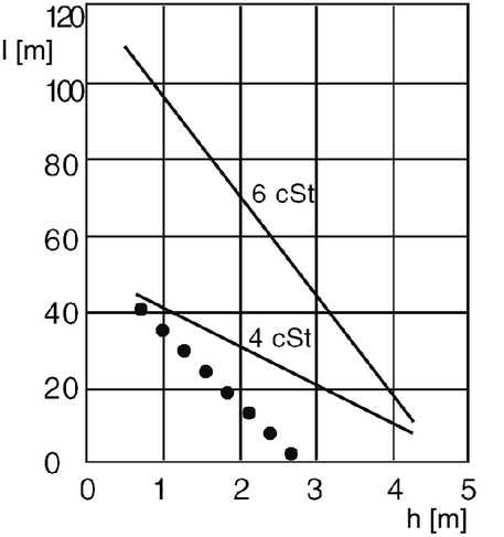
The negative pressure depends on:
the pipeline length
the suction height
the control panels, branches and angles in the suction line (dotted line in the diagram)
the pipeline cross-section
From +4 C, EL heating oil precipitates paraffin, which accumulates on the inner wall of the pipe.
the viscosity of the heating oil (temperature-dependent)
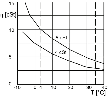
Measures against too high of negative pressure are:
Minimum inner pipe diameter 6 mm
short, preferably straight pipelines
In extreme cases, use a separate fuel line with feed pump
Preheat heating oil, provide suction line with trace heating
Maximum viscosity 4...6 cSt at 20 °C
If there is a risk of frost, use heating oil with additives (flow improvers) (winter fuel oil).
A prerequisite for the correct functioning of the washing station heater is that the washing station is designed by the customer in accordance with KÄRCHER's recommendations.
Connect the on-site pipes of the washing station heater to the distributors in the device.
Mount the outdoor temperature sensor:
protected from direct sunlight (north of the equator on the north side, south of the equator on the south side),
protected from warm walls,
protected from warm air currents.
Connect the immersion pump for filling the washing station heater to the filling valve (on the red distributor).
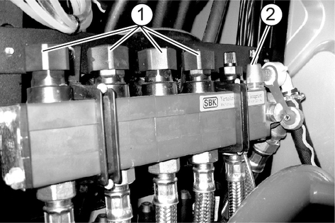
Lay the return line from the filling valve of the blue distributor to the tank with frost protection solution.
Open the flow stop valves and the filling valves.
Pump frost protection mixture into the system for frost protection down to minus 25 °C.
Switch on the floor heating pump (see chapter "Controller/Service menu").
Carry out the filling process until there are no more bubbles in the return line.
Close the return filling valve (on the blue distributor) and continue to fill in frost protection until the pressure gauge shows approx. 1.5 bar.
Close the filling line stop valve.
Let the underfloor heating pump run for at least another 15 minutes. If necessary, top up with frost protection until the pressure gauge shows 1.5 bar.
Remove the hose, collecting and disposing of the remaining frost protection solution.
Check the hose and pipe connections for leaks.
Set the thermostatic mixing valve, see chapter "Settings/Washing station heater",
The oil level on all high-pressure pumps must be between the MIN and MAX marks on the oil tank.
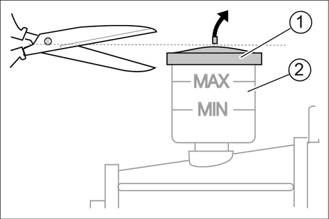
Cut off the tip of the oil tank cover on each high-pressure pump.
Fill with operating materials as described in the section "Filling with operating materials".
The softening salt is filled into the salt tank during the initial startup of the base exchanger. Therefore, do not add softening salt yet.
Open the water inlet.
Vent the hot water circulation pump by loosening the venting screw and then tightening it again.
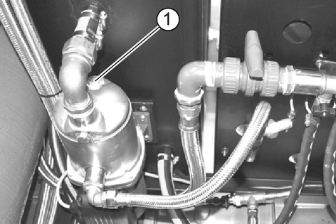
Turn the main switch to "1".
Vent the circulation pump frost protection by loosening the venting screw and then tightening it again.
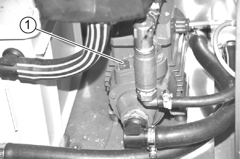
Insert the overflow hoses of the base exchanger and salt tank into the on-site waste water pipe.
Fill the salt tank with water (approx. 10 cm above the upper edge of the sieve). Do not add salt yet!
Slowly open the fresh water stop valve and wait until the pressure tank has filled with water.
Remove the cover of the control valve.
Press the programme button and select the "Backwash" function by turning it in the direction of the arrow."
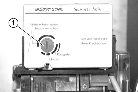
Air and water escape through the waste water connection until the system is completely vented.
Limit backwashing to the absolute minimum, otherwise the sensor measuring cell may be exhausted and a complete regeneration of the respective exchange tank will be necessary.
Pull the suction sieve attached to the brine hose out of the guide tubes in the salt container.
Press the valve flap NR1 (directly behind the programme unit) with a screwdriver.
The air shutter valve fills and air escapes through the suction sieve.
If no more air escapes from the suction sieve, release the valve flap.
Reinsert the suction sieve into the guide tubes.
Press the programme button and select the "Salting+Washing" function by turning it in the direction of the arrow."
The water level in the salt tank decreases continuously.
If air forms in the air shutter valve before the salt container is empty (residual level with empty salt container approx. 7cm) and the ball floating in the air shutter glass falls down, the suction system must be vented.
Press the programme button and select the "Fill+Wash clean" function by turning it in the direction of the arrow.
The control valve automatically moves to the "Operation" function. The salt tank is filled with water.
When the water level is correct, fill the salt tank with tablet salt according to DIN 19604 (see also chapter Accessories).
After completion of this work, the system is ready for operation.
Complete the initial startup of the base exchanger by carrying out a soft water check.
Fill the membrane with tap water pressure (wet).
Rinse the membrane for 10...20 minutes.
(Foam development during this process is normal).
Continue the rinse until no more bubbles are visible on the permeate flowmeter.
Check the pressure of the detergent solution.
Target value: 0.9...1.0 MPa (9...10 bar).
If necessary, correct the pressure by turning the adjustment screw on the pump.
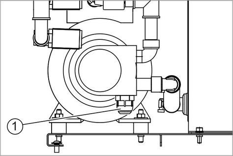
Check the burner setting.
Check all system functions.
Check all the washing programmes at all the washing stations.
Check the system for leaks and re-tighten screw connections if necessary.
The initial startup of gas burner may only be carried out by authorised specialist personnel of the burner manufacturer.
The device must be connected to its own chimney.
The exhaust system must be carried out in accordance with local regulations and in consultation with the responsible master chimney sweep.
Type B23
Gas device without flow protection, in which all parts of the exhaust gas path that are under excess pressure have combustion air flowing around them.
The B23 installation opens up the possibility of connecting the device to a conventional single-exhaust-gas chimney in accordance with DIN 18160 and operating it as room air dependent. The prerequisite is that the chimney is suitable for the connection of condensing boilers (e.g. by refurbishing the chimney by inserting a stainless steel pipe).
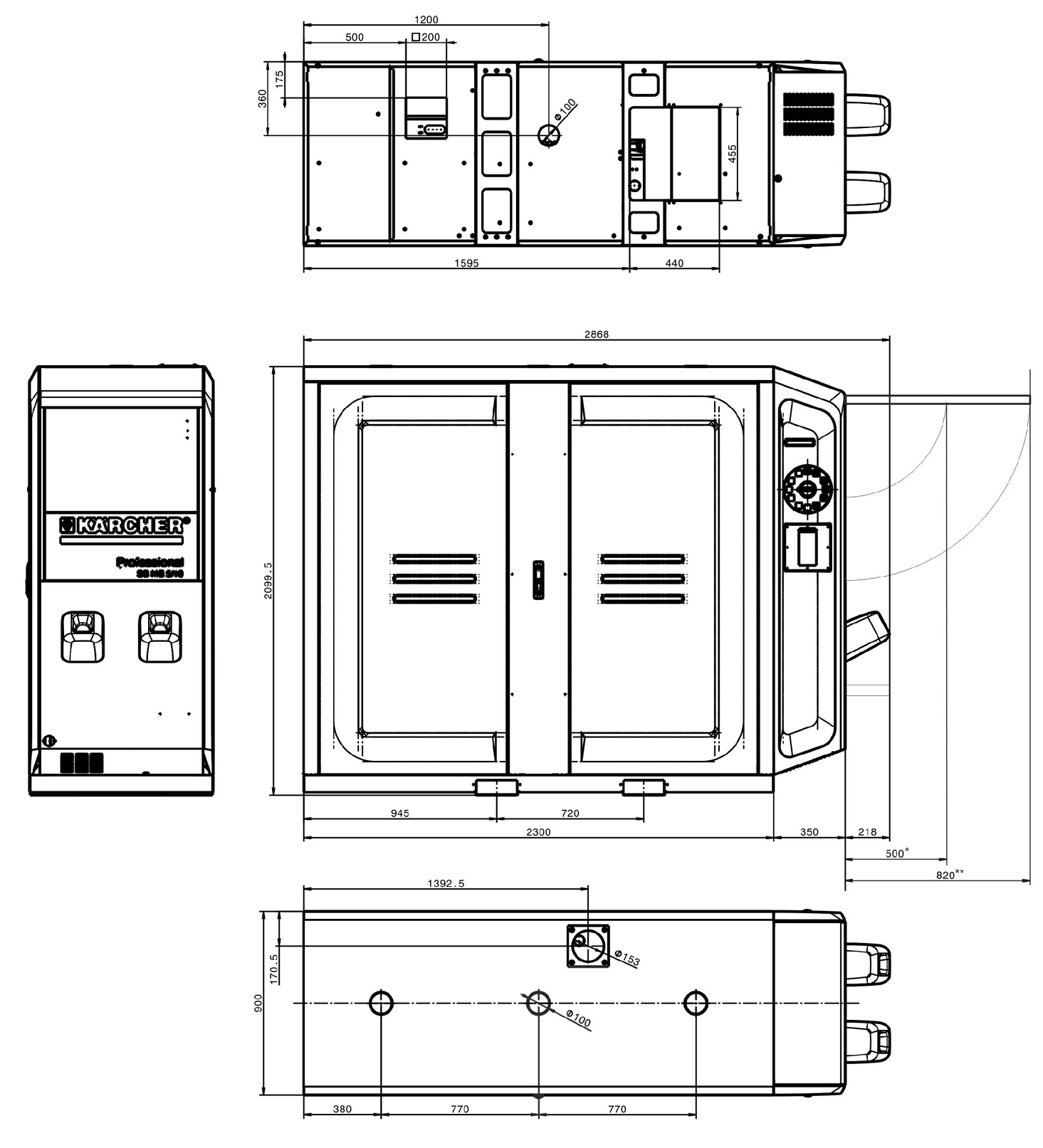
* SB MB standard
** SB MB comfort
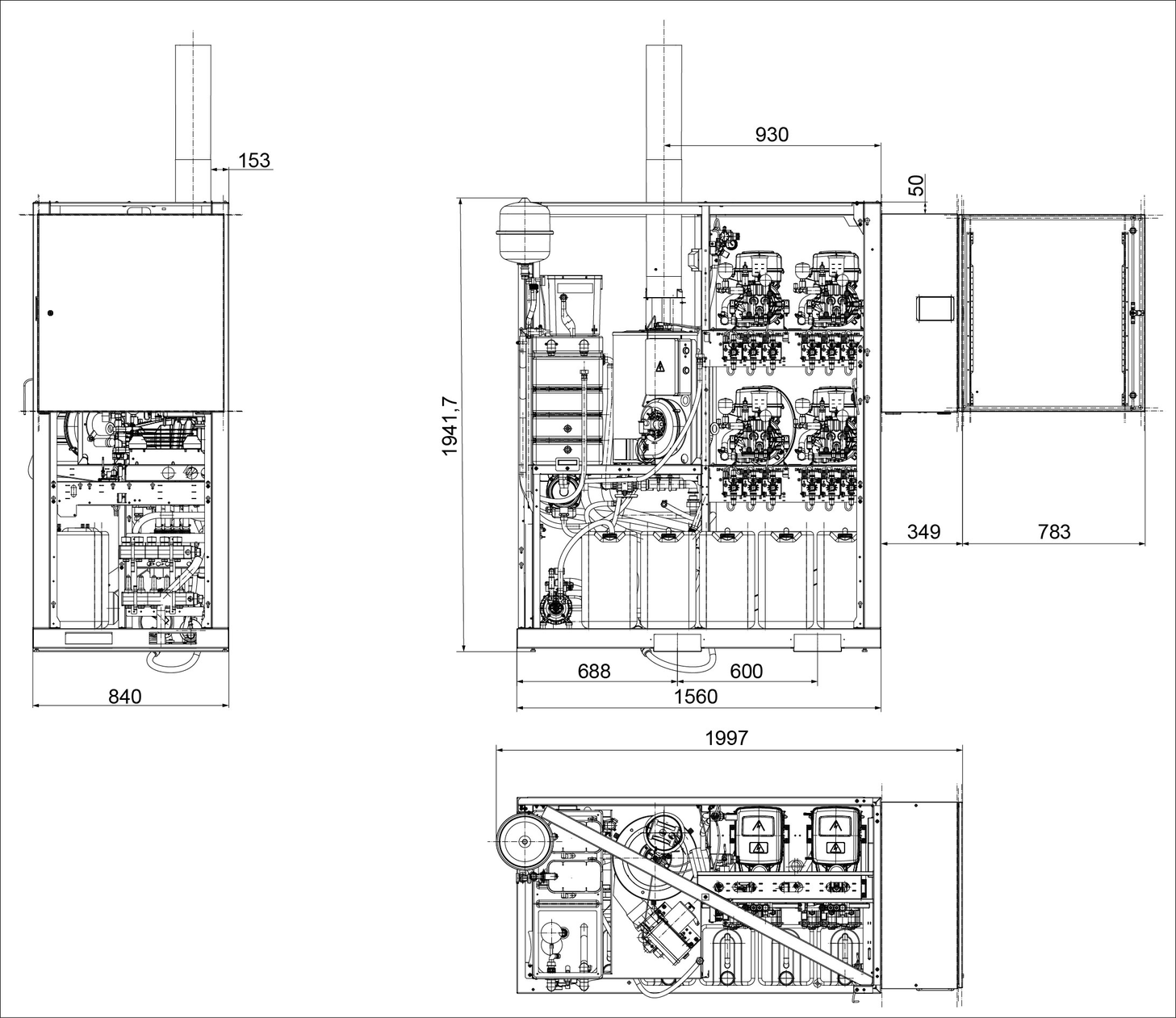
* SB MB standard
** SB MB comfort
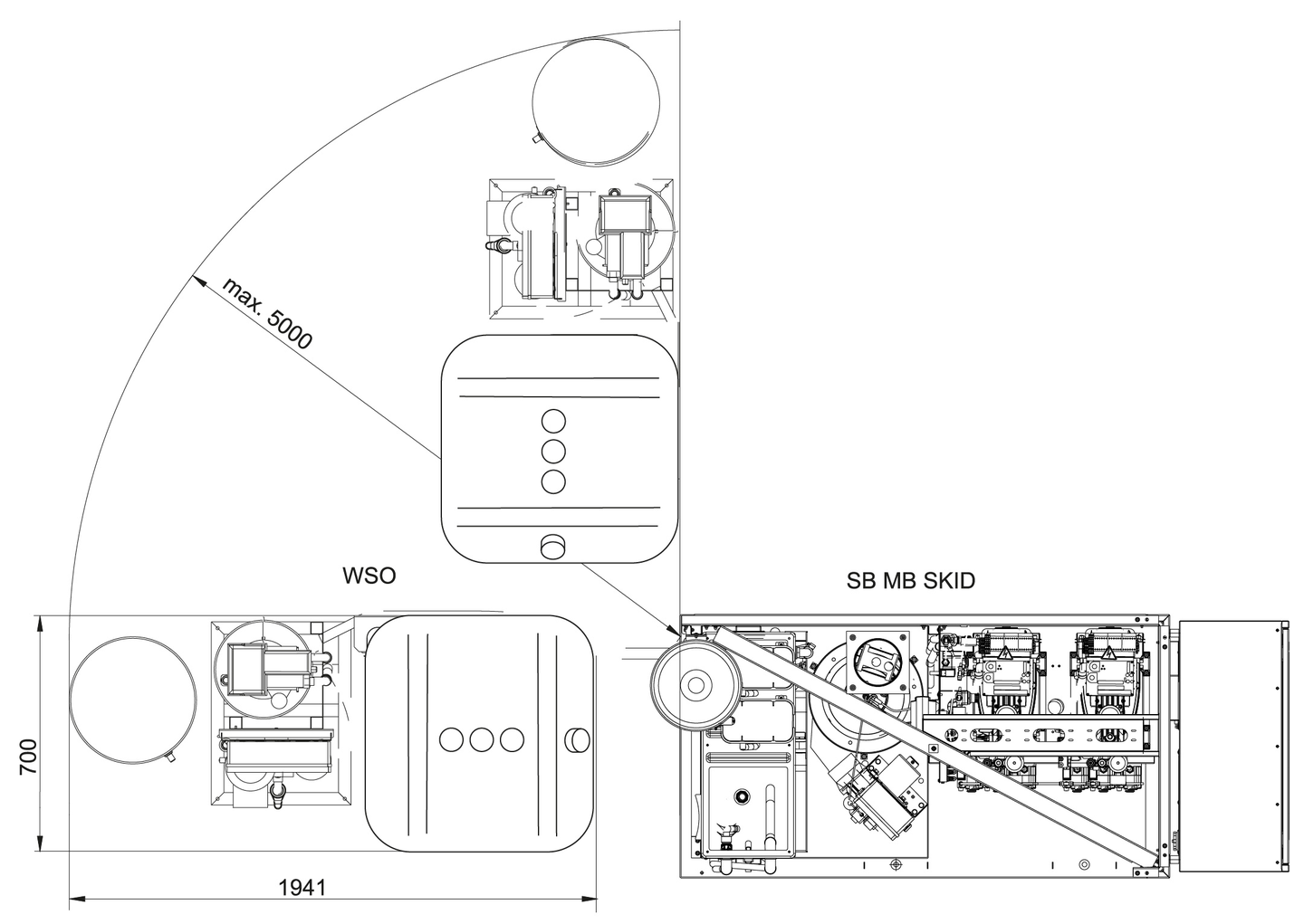
System type: | Manufacture no: | Initial startup on: |
 | ||
Test carried out on: | ||
Diagnosis: | ||
Signature | ||
Test carried out on: | ||
Diagnosis: | ||
Signature | ||
Test carried out on: | ||
Diagnosis: | ||
Signature | ||
Test carried out on: | ||
Diagnosis: | ||
Signature | ||
Test carried out on: | ||
Diagnosis: | ||
Signature | ||
EU Declaration of Conformity |
We hereby declare that the machine described below complies with the relevant basic safety and health requirements in the EU Directives, both in its basic design and construction as well as in the version placed in circulation by us. This declaration is invalidated by any changes made to the machine that are not approved by us.
Product: High-pressure cleaner
Type: 1.070-xxx
Currently applicable EU Directives2000/14/EC
2006/42/EC (+2009/127/EC)
2014/30/EU
2009/125/EC
2011/65/EU
Commission Regulation(s)(EU) 2019/1781
Harmonised standards usedEN 60335-1
EN 60335-2-79
EN 55014-1: 2017 + A11: 2020
EN 55014-2: 2015
EN 61000-3-2: 2014
EN 61000-3-3: 2013
EN 62233: 2008
EN IEC 63000: 2018
Applied conformity evaluation method2000/14/EG: Annex V
Sound power level dB(A)Measured: 86
Guaranteed: 88
The signatories act on behalf of and with the authority of the company management.

Documentation supervisor:
S. Reiser
Alfred Kärcher SE & Co. KG
Alfred-Kärcher-Str. 28 - 40
71364 Winnenden (Germany)
Ph.: +49 7195 14-0
Fax: +49 7195 14-2212
Winnenden, 2021/04/01
Declaration of Conformity (UK) |
We hereby declare that the product described below complies with the relevant provisions of the following UK Regulations, both in its basic design and construction as well as in the version put into circulation by us. This declaration shall cease to be valid if the product is modified without our prior approval.
Product: High-pressure cleaner
Type: 1.070-xxx
Currently applicable UK RegulationsS.I. 2001/1701 (as amended)
S.I. 2008/1597 (as amended)
S.I. 2016/1091 (as amended)
S.I. 2010/2617 (as amended)
S.I. 2012/3032 (as amended)
Commission Regulation(s)(EU) 2019/1781
Designated standards usedEN 60335-1
EN 60335-2-79
EN 55014-1: 2017 + A11: 2020
EN 55014-2: 2015
EN 61000-3-2: 2014
EN 61000-3-3: 2013
EN 62233: 2008
EN IEC 63000: 2018
Applied conformity assessment procedureS.I. 2001/1701 (as amended): Schedule 8
Sound power level dB(A)Measured: 86
Guaranteed: 88
The signatories act on behalf of and with the authority of the company management.
Documentation supervisor:
S. Reiser
Alfred Kärcher SE & Co. KG
Alfred-Kärcher-Str. 28 - 40
71364 Winnenden (Germany)
Ph.: +49 7195 14-0
Fax: +49 7195 14-2212
Winnenden, 2021/04/01