0.084-116.0 (03/24)
0.084-116.0 (03/24)
 Read and adhere to these installation instructions before conversion.
Keep these installation instructions for future reference or for future owners.
Risk of asphyxiation. Keep packaging film out of the reach of children.
Only use the device for its proper use. Take into account the local conditions and beware of third parties, in particular children, when working with the device.
The device is not intended for use by persons with restricted physical, sensory or mental abilities or those lacking in experience and / or lacking in knowledge.
Only people who have been instructed on how to use the device, or have proven their ability to operate it, and have been explicitly instructed to use it, must use the device.
Children must not operate the device.
Children must be supervised to prevent them from playing with the appliance.
Safety devices are provided for your own protection. Never modify or bypass safety devices.
The antenna must be attached to the machine in such a way that the machine operator is 20 cm away from the antenna.
Indication of an imminent threat of danger that will lead to severe injuries or even death.
Indication of a potentially dangerous situation that may lead to severe injuries or even death.
Indication of a potentially dangerous situation that may lead to minor injuries.
Indication of a potentially dangerous situation that may lead to damage to property.
Risk of damage due to improper installation.
Improper installation or connecting up of the attachment can damage the attachment as well as the vehicle or the machine. Malfunctions and failures can occur on the attachment and the vehicle or machine.
Have the assembly, installation and connecting up of the attachment carried out only by a qualified specialist.
Risk of damage due to electrostatic discharge (ESD)!
Electrostatic discharge (ESD) can damage electronic components.
Take suitable measures to discharge the electrostatic charge before all work on the device electronics.
Risk of damage due to sharp-edged objects and soiling!
Sharp-edged or dirty objects can cause damage such as scratches, notches and deformation when coming into contact with device components. Dirty tools, cloths and work surfaces can cause irreversible soiling and discolouration.
Use only suitable, undamaged and clean tools and auxiliary materials and exercise care when working. Place components and devices only on clean, padded surfaces.
For safety and warranty reasons, we recommend that you have Kärcher Service perform the assembly, installation and connection.
Keep these installation instructions for future reference or for future owners.
Also adhere to the operating instructions for the vehicle or device in which the attachment is installed.
Canada
This device contains licence-exempt transmitters/receivers that comply with Innovation, Science and Economic Development Canada’s licence-exempt RSS(s). Operation is subject to the following two conditions:
This device may not cause interference
This device must accept any interference, including interference that may cause undesired operation of the device.
USA:
This device complies with part 15 of the FCC Rules. Operation is subject to the following two conditions:
This device may not cause harmful interference, and
this device must accept any interference received, including interference that may cause undesired operation.
Changes or modifications not expressly approved by the party responsible for compliance voids the user's authority to operate this equipment.
This equipment has been tested and found to comply with the limits for a Class B digital device, pursuant to part 15 of the FCC Rules. These limits are designed to provide reasonable protection against harmful interference in a residential installation. This equipment generates, uses and can radiate radio frequency energy and, if not installed and used in accordance with the instructions, may cause harmful interference to radio communications. However, there is no guarantee that interference will not occur in a particular installation. If this equipment does cause harmful interference to radio or television reception, which can be determined by turning the equipment off and on, the user is encouraged to try to correct the interference by one or more of the following measures:
Reorient or relocate the receiving antenna.
Increase the separation between the equipment and receiver.
Connect the equipment into an outlet on a circuit different from that to which the receiver is connected.
Consult the dealer or an experienced radio/TV technician for help.
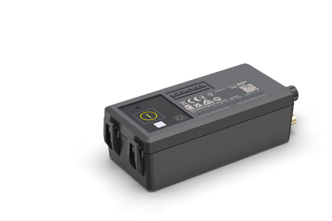
The Equipment Management - Plug-in Connect Module, is used to transmit important status and usage data of a device. These installation instructions describe the installation and the connection.
These installation instructions apply to the attachment kit:
2.644-391.0
Description | Quantity | Part number |
|---|---|---|
Plug-in Connect Module | 1 | 2.644-391.0 |
Mobile radio antenna | 1 | 6.684-583.0 |
Cable ties | 2 | 6.641-458.0 |
Mounting element, self-adhesive | 2 | 6.648-813.0 |
Cleaning set | 1 | 6.039-043.0 |
Ring cable lug D4-1 | 2 | 6.641-242.0 |
Ring cable lug D5-1 | 2 | 6.641-086.0 |
Ring cable lug D8-1 | 2 | 6.642-602.0 |
Ring cable lug D10-1 | 2 | 6.642-603.0 |
RJ 45 adapter for BR 45/22 | 1 | 6.642-604.0 |
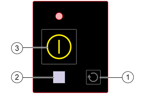
LED off: neutral
LED on: blue
Place the device on a level surface.
Switch off the device.
Turn the program selection switch to position "0".
If present: Pull out the KÄRCHER Intelligent Key (KIK) on the control panel.
Disconnect the battery.
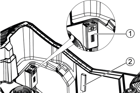
Determine a suitable position for the Plug-In Connect Module and the antenna in the device (see Determine the position for the Plug-in Connect Module and the antenna).
Material damage through incorrect installation
Allow only qualified staff to perform the installation.
After installation, keep the installation instructions and the circuit diagram together with the operating instructions.
The following requirement should be met by the position for attachment:
The Plug-in Connect Module must be fitted in such a way as to ensure the best possible transmission of the device's vibrations.
Move the Plug-in Connect Module near the main unit (e.g. turbine, motors) of the device (for an example of the attachment, see Machine integration and installation position).
The antenna must be glued to the outer wall inside the device.
The shielding by components such as metal and electronic components as well as e.g. the fresh water tank should be as low as possible.
The adhesive surface should be as flat as possible.
The Plug-in Connect Module should only be in contact with the machine at the adhesive surface when the device is ready for operation. The remaining outer surfaces of the module should be exposed.
Material damage due to improper attachment!
If the module is not attached properly, it may detach from the attached surface and fall onto other elements inside the device.
Attach the Plug-in Connect Module in such a way that it does not come into contact with moving or safety-relevant components of the device in the event of detachment.
Risk of damage to the cable!
The cable between the antenna and the Plug-in Connect Module can be damaged by crushing or kinking.
Do not place heavy objects on the cable and do not pinch it.
Do not pull, bend, alter or wrap the cable.
The adhesive surfaces must be cleaned with the enclosed cleaning kit before glueing the antenna and Plug-in Connect Module together.
Cleaning the bonding surfaces immediately before bonding is essential for the success of a good and permanently strong bond.
For proper cleaning and installation, use the instructions, part no. 0.093-405.0.
Further information about the following products can be found on the product detail page of the manufacturer 3M:
3M™ VHB™ Surface Cleaner
3M™ VHB™ Tape 5952F
Clean the adhesive surface with the enclosed cleaning kit.
Remove the protective film from the adhesive surface.
Attach the Plug-in Connect Module at a suitable place (seeDetermine the position for the Plug-in Connect Module and the antenna).
Glue the antenna.
Shorten the power supply cable to the device-specific length.
Attach the device-specific connector (e.g. ring cable lug) to the open end of the cable.
Contact the internal power supply in the device (supply voltage 12-60 V) with connectors.
Activate the Plug-in Connect Module with the On/Off button on the HMI.
Press the On/Off button on the HMI (approx. 10 seconds) until the blue LED lights up continuously.
Start the Plug-in Connect Module via the following link:
https://support.em.kaercher.com/loginTurn the trigger to "0".
Unscrew the M 5x20 screw (2x).
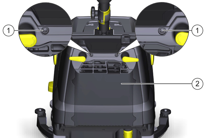
Open the cover.
Release and disconnect the battery plug connector.
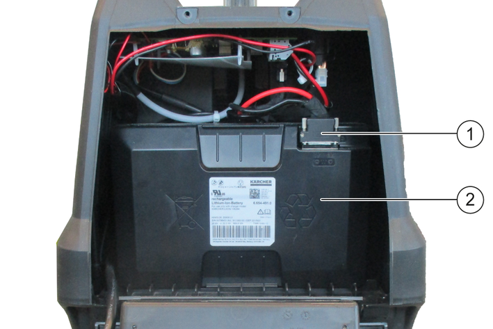
Attach the Plug-in Connect Module and the antenna as shown.
Risk of damage to the cable!
The cable between the antenna and the Plug-in Connect Module can be damaged by crushing or kinking.
Do not place heavy objects on the cable and do not pinch it.
Do not pull, bend, alter or wrap the cable.
Strip the cable (approx. 100 mm).
Place the ring cable lug D4-1 on the wire of the cable and then crimp it with a crimping tool (2x).
Remove the plastic cover from the control board.
Attach the ring cable lugs with the flattened side:
Red wire (positive pole): Slot X9
Black wire (negative pole or ground point): Slot GND:X13
Reinsert the battery into the device and connect it accordingly.
Secure the cable to the wiring harness with the cable ties and route it accordingly.
Press and hold the On/Off button on the Plug-in Connect Module for approx. 10 seconds.
The LED must then light up continuously.
Close the cover again.
Screw in the M 5x20 screw (2x).
Turn the trigger to "0".
Unscrew the M 5x20 screw (2x).

Open the cover.
Release and disconnect the battery plug connector (4x).
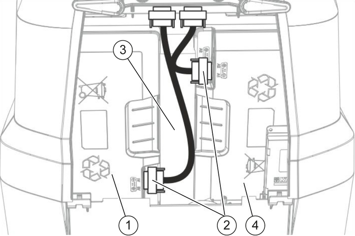
Remove the battery spacer.
Remove the left battery (view direction: in the direction of travel).
Bond the Plug-in Connect Module and the antenna as shown.
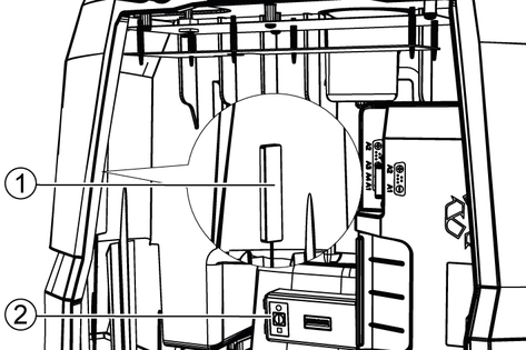
The antenna must be attached on the inside, to the left of the RJ 45 adapter.
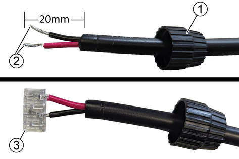
Strip the cable (20 mm).
Put the screw cap on the cable.
Insert into the wiring cap.
Pin 1: (WhiteOrange/Whitegreen) positive pole (red cable).
Pin 2: (blue) negative pole (black cable).
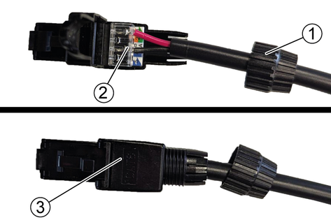
Press the wiring cap onto the plug.
Close the plug and screw it with the screw cap
Risk of damage to the cable!
The cable between the antenna and the Plug-in Connect Module can be damaged by crushing or kinking.
Do not place heavy objects on the cable and do not pinch it.
Do not pull, bend, alter or wrap the cable.
Place the ring cable lug D4-1 on the wire of the cable and then crimp it with a crimping tool (2x).
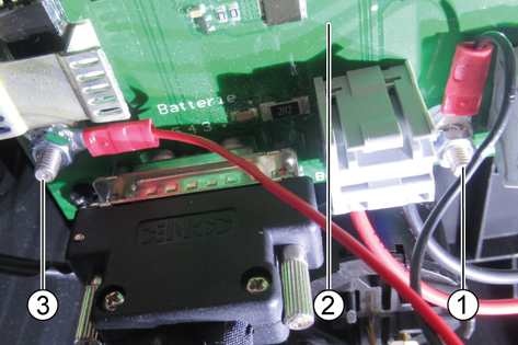
Remove the plastic cover from the control board.
Attach the ring cable lugs with the flattened side:
Red wire (positive pole): Slot X3
Black wire (negative pole or ground point): Slot X4
Insert the battery plug connector of the battery on the right and tighten it (2x).
The Plug-in Connect Module must be checked for full functionality before inserting the left battery.
Press and hold the On/Off button on the Plug-in Connect Module for approx. 10 seconds.
The LED must then light up continuously.
Reattach the cover.
Fit the left battery.
Insert the battery spacer between the batteries.
Insert the battery plug connector of the battery on the left and tighten it (2x).
Close the cover.
Screw in the M 5x20 screw (2x).
Turn the programme selection switch to "OFF".
Remove the waste water tank.
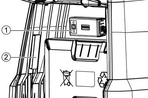
Bond the antenna on the right inside (in driving direction) of the fresh water tank behind the battery.
Bond the Plug-in Connect Module on the front inside (in travel direction) of the fresh water tank.
The Plug-in Connect Module must not be placed higher than the lower edge of the waste water tank (see diagram above).
Risk of damage to the cable!
The cable between the antenna and the Plug-in Connect Module can be damaged by crushing or kinking.
Do not place heavy objects on the cable and do not pinch it.
Do not pull, bend, alter or wrap the cable.
Remove the pole cap (2x).
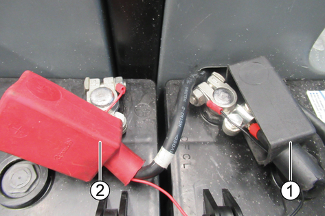
Release the nut on the battery terminal (2x).
Strip the cable (approx. 150 mm).
Place the ring cable lug D8-1 on the wire of the cable and then crimp it with a crimping tool (2x).
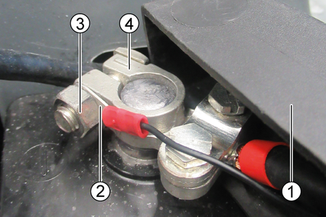
Pull the ring cable lug through the opening in the pole cap (2x).
Attach the ring cable lug with the flattened side (pointing towards the battery terminal) and secure it with the nut (2x).
The red cable must be connected to the positive pole and the black cable to the negative pole or earth point.
Press and hold the On/Off button on the Plug-in Connect Module for approx. 10 seconds.
The LED must then light up continuously.
Fit the pole cap (2x).
Fit the waster water tank.
The initial startup takes place via the "EQUIPMENT MANAGEMENT ADMIN VIEW" portal
Link to portal: https://support.em.kaercher.com/
QR code to portal:
In case of questions or malfunctions, please contact the following e-mail address: info.em@karcher.com
Dimensions and weights | |
Weight | 1.7(0,23) lbs (kg) |
Length x width x height | 5.3x2.2x1.54 in |
Cable length | 66.9 in |
Antenna cable length | 19.7 in |
External communication | |
Network technology | Mobile networkWLAN |
Input voltage | |
Input voltage range | 12...60 V |
Power input max. | 1 A |
Average standby power consumption | <1 mA |
Reverse-polarity protection (up to) | 75 V |
Ambient conditions | |
Permissible temperature range | 23-104 |
Relative humidity | 20...85 % |
Degree of protection | IP45 |
Casing material | PP RoHS 2 |
Contains Li-ion Rechargeable Cell | |
Type | ICR18650/20P (ICR19/66) |
Nominal voltage | 3,6 V |
Capacity | 2000 (7.2) mAh (Wh) |