2.042-033.0
00842030 (01/25)
00842030 (01/25)
 Before mounting, read these assembly instructions and the safety instructions, as well as the operating instructions and the safety instructions of the appliance / machine / vehicle.
Keep the assembly instructions, operating instructions and safety instructions for later use or for subsequent owners.
Installation, service and maintenance work may only be carried out by suitably qualified and specially trained specialist personnel, and we recommend installation by Kärcher Service.
Indication of an imminent threat of danger that will lead to severe injuries or even death.
Indication of a potentially dangerous situation that may lead to severe injuries or even death.
Indication of a potentially dangerous situation that may lead to minor injuries.
Indication of a potentially dangerous situation that may lead to damage to property.
Risk of damage due to improper installation!
Incorrect installation may result in damage, malfunctions and failures of the device/machine/vehicle.
Assembly, installation and connection may only be carried out by a qualified specialist.Risk of damage due to sharp-edged objects and soiling!
Sharp-edged or dirty objects can cause damage such as scratches, notches, and deformations when in contact with components. Dirty tools, cloths, and work surfaces can cause irreversible stains and colour changes.
Use only suitable, undamaged and clean tools and aids, and act with care. Place components and devices only on clean, padded surfaces.Risk of damage due to improperly installed cables and hoses!
Improperly installed lines and hoses can cause damage, malfunctions and failures of parts or device / machine / vehicle.
Do not kink lines and hoses and do not subject them to tension, compression or torsion.Ensure that the lines and hoses are routed so that they are free from chafing and at a sufficient distance from hot components, and do not run them over corners or edges or over sharp or pointed parts.Do not fall below the smallest permissible bending radii.If necessary, fasten the lines and hoses with suitable means, do not restrict the required degrees of freedom.Lay and secure cables and hoses so that they are not crushed or compressed and do not come into contact with rotating parts such as wheels, rollers, rollers, brushes, etc.Observe the warnings in the chapters!
The docking station is suitable for commercial and industrial use, e.g. in production, warehouse and exhibition halls.
The docking station may only be operated with the casing installed.
Any other use is not permitted and considered as improper use.
These installation instructions describe the installation process for the docking station.
The docking station can be used forKIRA B 200Autonomously perform the following tasks after docking:
Filling the fresh water tank
Emptying and rinsing the waste water tank
Charging the traction batteries LIB
The docking station may only be operated with the casing installed.
Any other use is not permitted and considered as improper use.
The installation takes approx. 45 minutes.
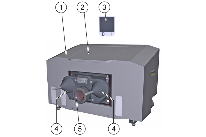
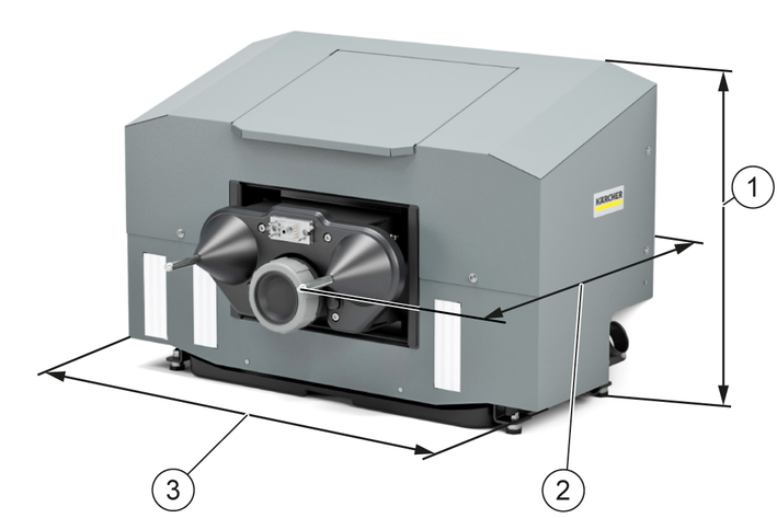
Overview of the unit
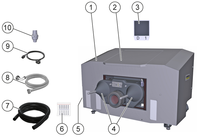
* required, not included in the scope of delivery
** Optionally available
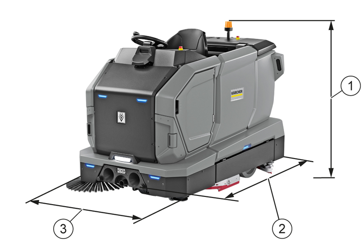
For safe and trouble-free operation, the following requirements must be met at the installation location of the docking station:
Frost-protected interior space that can be approached by the machine.
Vertical, flat, fixed, load-bearing wall for attaching the docking station.
Horizontal, flat, closed clearance with a minimum load-bearing capacity equal to the maximum permissible total weight of the machine.
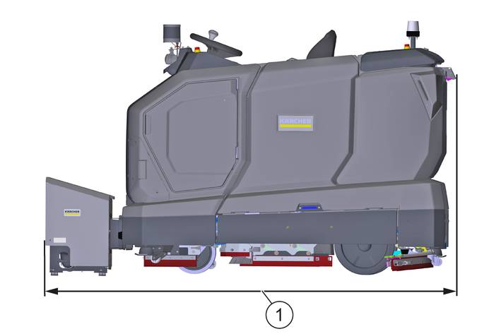
For the minimum dimensions of the open space, see graphic.
Always keep the open space clear of persons, animals and objects.
If necessary, install collision protection devices in the specified areas.
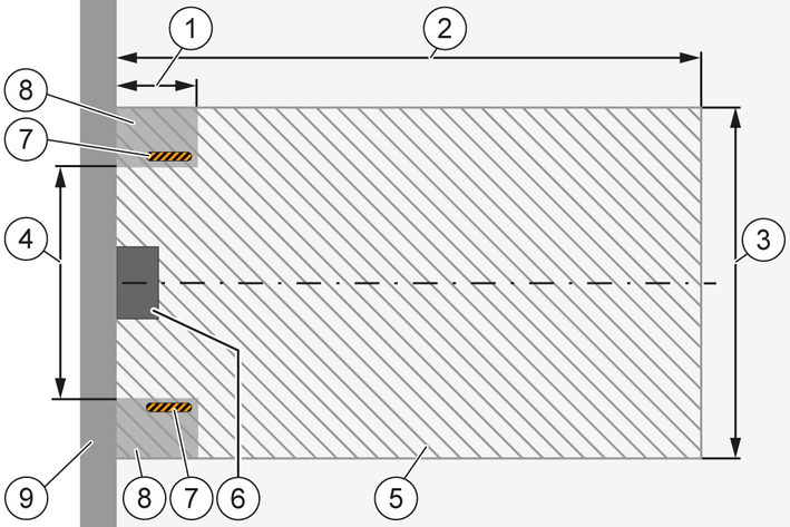
The installation location and the open space must not be in the area of footpaths or travel paths and must not be frequented by public traffic.
Mains socket with protective contact present, protected by a country-specific fault current circuit breaker, for connected loads seeTechnical data.
Fresh water tapping point present on the building side, for connected loads seeTechnical data.
Waste water disposal point on the building side must be located deeper than the waste water hose connection of the docking station.
Disassemble the housing on the docking station.
Place the docking station on the cleaned floor surface and push it against the wall until it is flush.
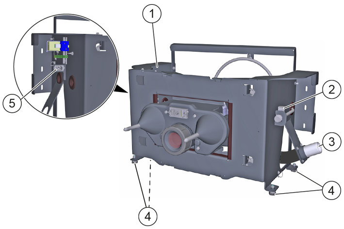
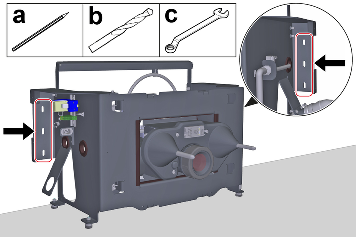
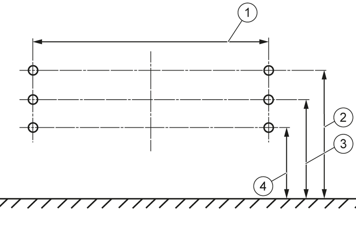
Mount the docking station to the wall:
Align the docking station horizontally and mark the outlines of the slots on the wall.
Drill a hole in the center of each marked spot.
This is the only way to adjust the height of the docking station up or down later.
Align the docking station horizontally and secure it to the wall with the screws.
Use fastening materials suitable for the wall type. The screw diameter must 6 mm .
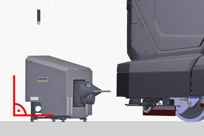
Move the machine centrally in front of the tips of the docking station centring cones.
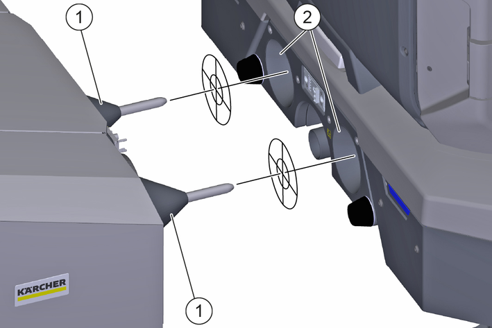
Check that the tips of the centring cones are aligned with the centring cone mounts on the device.
Do not align, measure the height difference and set the mounting height of the docking station accordingly, seeSetting the installation height.
Unscrew the screws securing the docking station to the wall.
Remove the docking station feet and remove or insert the required number of washers.
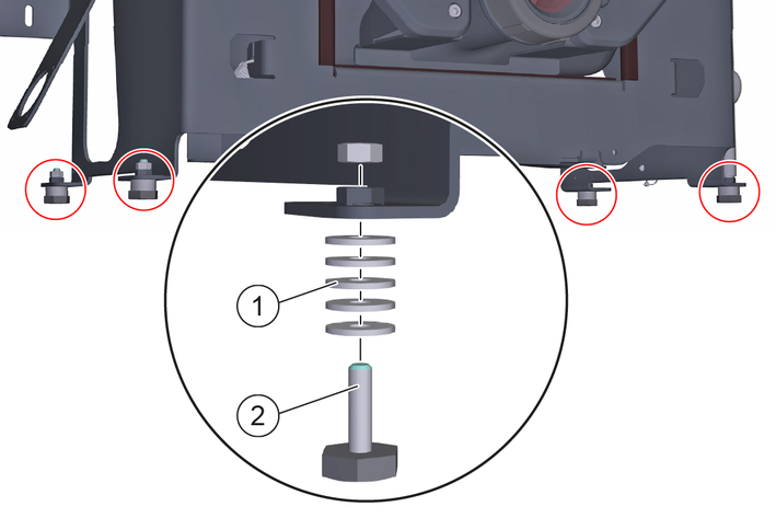
Mount the feet on the docking station.
Mount the docking station horizontally on the wall.
All feet must rest flat on the floor area.
Check the installation height again and repeat the adjustment process if necessary.
Risk of damage due to excessive water supply pressure!
Material damage
Make sure that the maximum permissible water inlet pressure is not exceeded.If necessary, install a pressure reducer.Install a pressure reducer if you cannot determine the water supply pressure.Check the building water supply pressure, see Technical data and adjust if necessary.
If necessary, install a pressure reducer.
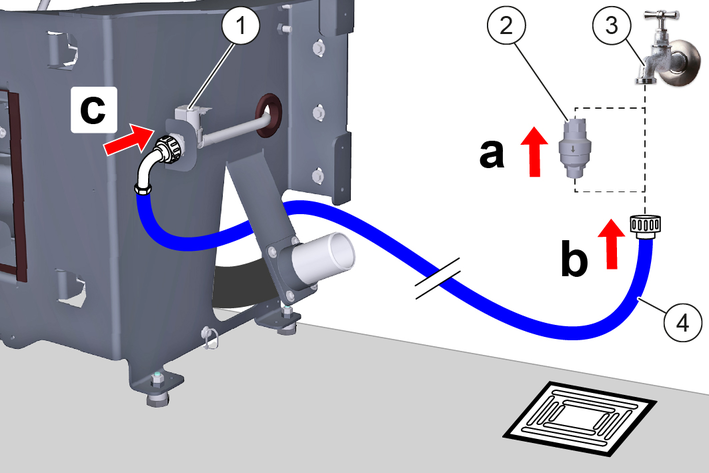
Connect the Aquastop hose:
Optionally, screw a water stop valve onto the building’s water tap, see Installing the water stop valve.
Screw the Aquastop hose onto the building's water tap or onto the optional water stop valve.
Route the Aquastop hose to the fresh water solenoid valve on the docking station and screw it on.
Has the water stop valve triggered during operation:
Eliminate the cause of the triggering.
Reset the water stop valve, see Resetting the water stop valve.
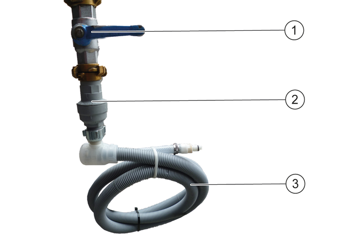
To ensure that no water overflows at the docking station, a water stop valve can also be installed. The water stop valve is mounted between the tap and the Aquastop hose.
Turn off the water supply.
Set the arrow to level 8 (40 litre water flow) with the spanner provided.
The water stop valve can be set from level 1 (5 litre water flow) to level 10 (50 litre water flow) and closes automatically when more than the set amount of water has flowed through without interruption.
Attach the upper end of the water stop valve to the tap.
At the entrance of the water stop valve, an upwardly curved Water filter is installed. If the Aquastop hose has a Filter mounted, it must be replaced by a gasket to ensure the function of the Water Stop Valve.
Attach the AquaStop hose to the thread at the bottom of the water stop valve.
Turn the water supply back on.
Turn off the water supply.
Remove the AquaStop hose.
Turn off the water stop valve and press in the red pin.
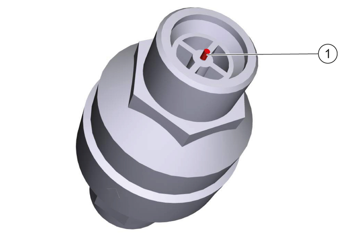
Attach the upper end of the water stop valve to the tap and press in the red pin.
Attach the AquaStop hose to the thread at the bottom of the water stop valve.
Turn the water supply back on
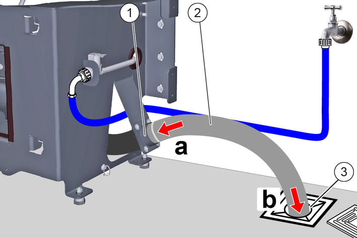
Install the waste water hose spout on the left or right of the docking station.
Observe the minimum bending radius of the waste water hose, seeTechnical data.
Use suitable pipes, hoses, seals and fasteners for the connection, depending on local conditions (shown as an example with waste water hose).
Install a suitable waste water hose:
Mount the waste water hose on the waste water hose spout of the docking station.
Install the waste water hose at a waste water disposal site.
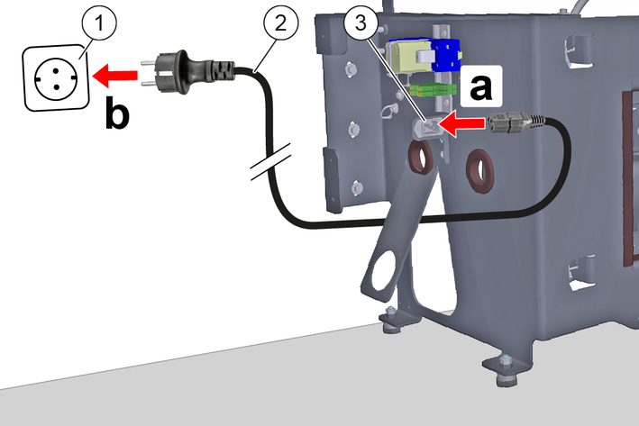
Danger of death from electric shock.
If the device is operated at a socket without an error current circuit breaker or without a protective contact (earthing), there is a danger of death from electric shock in the event of a fault!
Only operate the device at sockets with an earthing contact and with an error current circuit breaker with a nominal fault current of max. 30 mA.Connect the power cable:
Plug the power cable into the power cable socket on the docking station.
Route the power cable to a power outlet with a protective contact and plug it in.
Do not laminate the position codes or place them in clear plastic sleeves, otherwise malfunctions may occur.
Temporarily mount the housing to the docking station.
Only screw the screws in a few turns.
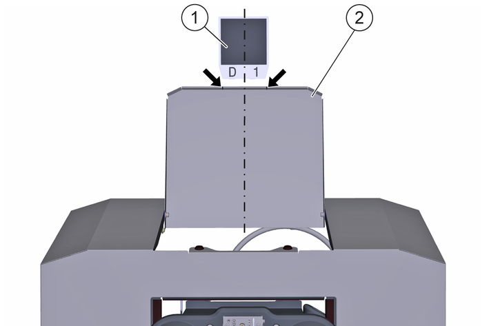
Attach the position code to the wall:
Open the flap until it rests against the wall.
Stick the position code to the wall, centered between the notches (arrows) and a short distance from the flap.
The bonding area must be flat, clean and free of grease.
Close the flap.
Remove the casing at the docking station.
Establish the voltage and fresh water supply.
Dock the machine to the docking station.
Check all water lines, hoses and connections for leaks and eliminate any leaks.
Check the functions:
Filling the fresh water tank
Drain and rinse the waste water tank
Charging the LIB traction batteries
Eliminate any faults.
Undock the machine from the docking station.
Mount the casing.
Danger of death from electric shock if live parts are touched!
Fatal or severe injuries
Do not touch any live parts.Unplug the mains plug from the mains socket before working on the device.Only operate the device with the casing installed.Risk of injury due to sudden start-up of the device!
Serious injuries
Unplug the machine and switch the machine off before performing any work on the docking station.Unplug the mains plug from the mains socket before working on the docking station.For maintenance intervals and maintenance positions, see operating instructionsKIRA B 200.
Risk of damage if cleaned improperly!
Material damage
Do not clean the device with water jets or hard, abrasive utensils, but use only soft, damp cloths.Do not use abrasive or aggressive cleaning agents.Do not rub sensitive surfaces dry.If necessary, clean the following parts with a soft, damp cloth:
Casing
Flap
Position code
Centering cone
Sealing collar
To prevent clogging and leaks, clean the waste water basin and sealing collar weekly and it may be necessary to shorten the interval depending on the composition and amount of waste water.
Pull the mains plug out of the mains socket.
Open the flap until it touches the wall.
Clean the waste water basin inside:
Unscrew the cover on the waste water basin.
Rinse the waste water basin with a water jet.
Screw the cover to the waste water basin.
The sealing ring must be undamaged, clean and correctly installed in the cover.
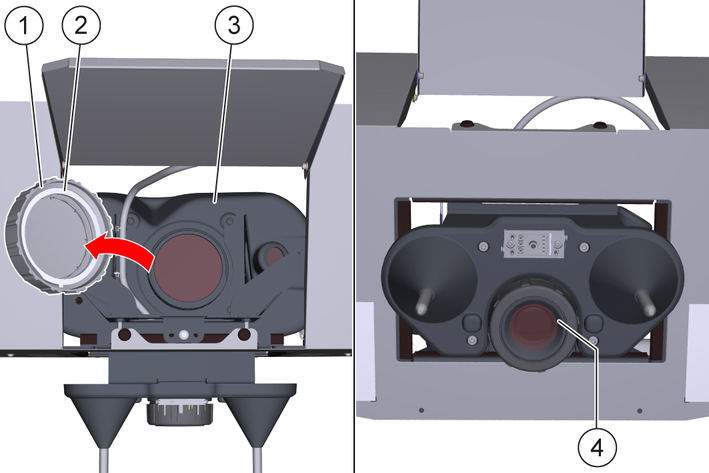
Clean the sealing collar with a damp cloth.
Close the flap.
Insert the mains plug into the mains socket.
EU Declaration of Conformity |
We hereby declare that the product named below complies with the relevant provisions of the directives and regulations listed. This declaration is invalidated by any changes made to the product that are not approved by us.
Product: Kira Docking Station
Type: 2.042-xxx
Directives and Regulations2006/42/EC (+2009/127/EC)
2011/65/EU
Harmonised standards usedEN 60335-1
EN 60335-2-72
EN IEC 63327
EN IEC 63000: 2018
Name and addressDocumentation supervisor:
S. Reiser
Alfred Kärcher SE & Co. KG
Alfred-Kärcher-Str. 28 - 40
71364 Winnenden (Germany)
Tel.: +49 7195 14-0
Fax: +49 7195 14-2212

Winnenden, 2025/11/01
The undersigned act on behalf of and with the authority of the Board of Directors.
Alfred Kärcher SE & Co. KG
Alfred-Kärcher-Str. 28 - 40
71364 Winnenden (Germany)
Ph.: +49 7195 14-0
Fax: +49 7195 14-2212
Declaration of Conformity (UK) |
We hereby declare that the product named below complies with the relevant provisions of the directives and regulations listed. This declaration is invalidated by any changes made to the product that are not approved by us.
Product: Kira Docking Station
Type: 2.042-xxx
Directives and RegulationsS.I. 2008/1597 (as amended)
S.I. 2012/3032 (as amended)
Designated standards usedEN 60335-1
EN 60335-2-72
EN IEC 63327
EN IEC 63000: 2018
Name and addressDocumentation supervisor:
S. Reiser
Alfred Kärcher SE & Co. KG
Alfred-Kärcher-Str. 28 - 40
71364 Winnenden (Germany)
Tel.: +49 7195 14-0
Fax: +49 7195 14-2212
Winnenden, 2025/11/01
The undersigned act on behalf of and with the authority of the Board of Directors.
Alfred Kärcher SE & Co. KG
Alfred-Kärcher-Str. 28 - 40
71364 Winnenden (Germany)
Ph.: +49 7195 14-0
Fax: +49 7195 14-2212
Electrical connection | |
Nominal voltage | 100-240 V |
Protection type | IPX3 |
Frequency | 50-60 Hz |
Power | 2250 W |
Water connection | |
Feed pressure (max.) | 1,0 MPa |
Input temperature (max.) | 50 °C |
Minimum bending radius of waste water hose | 65 mm |
Lifting unit requirement | |
Pumping capacity of the wastewater lifting station | ≥ 6,5 m3/h |
Minimum slope of waste water pipe | 1 ° |
Dimensions and weights | |
Length x width x height | 864x571x614 mm |
Weight | 43 kg |

2-2-SC-A4-GS-17339