WRB 2000 Bio, WRB 4000 BioWRB 4000 L Bio, WRB 4000 DF Bio
59681090 (03/23)
59681090 (03/23)
Read these operating instructions before using the system for the first time. Also observe the original data sheets provided in the appendix and the operating manuals for the units used. Keep these documents for future reference or for future owners.
Target group for these instructions:
Operator
Technical specialists (persons possessing the necessary technical training allowing them to erect and commission the system)
Instructed assistant personnel
Definitions:
Fresh water is tap water.
Waste water is the dirty water coming from the washing facility.
Recycling / processed water is the treated water coming from the treatment system that is re-used in the vehicle washing facility.
The system requires a running-in phase of 3-6 weeks in order to develop its full cleaning performance. The running-in phase begins on the day when waste water containing treatable substances (mineral oils and company-internal waste water) is regularly channelled into the system. During the running-in phase, the microbiological system can temporarily produce increased quantities of foam in the washing facility. Do not supply any heavily contaminated waste water into the system during the running-in phase.
It has been observed that the drainage channels in the washing halls and the sludge traps of the separator system are misused for disposing of waste during the installation process. To prevent system malfunctions during operation, such as clogging or damage to the pumps, clean all foreign materials from the drainage channels before channelling waste water into the system for the first time.
The waste water resulting from the cleaning of buildings (walls, floors, containers etc.) may not be cleaned in the treatment system. The system is not designed for processing or disposing of this type of waste water.
aquadetox international GmbH accepts no liability of any kind for damage or operational malfunctions resulting from inadequate cleaning of the entire system.
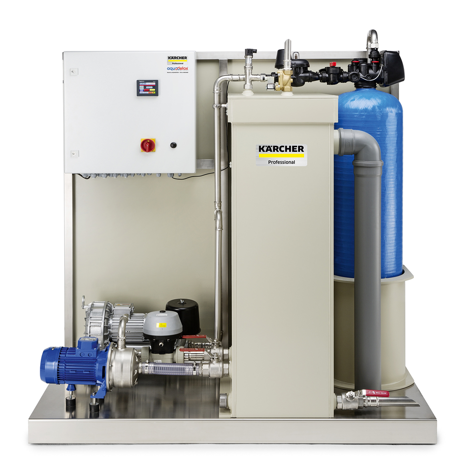
The BioSaver® / WRB Bio is a biological process for waste water treatment. The system is intended for cleaning and recycling the waste water generated by various different types of vehicle washing facilities. The recycling water may only be used for washing programs (e.g. pre-cleaning, high-pressure cleaning, brush cleaning).
The waste water is cleaned through:
Settling of non-soluble particles in the sludge trap
Separation of the excess sludge in the post-treatment stage
Substance transfer of the soluble substances in the biological stage
 The packing materials can be recycled. Please dispose of packaging in accordance with the environmental regulations.
 Electrical and electronic devices contain valuable, recyclable materials and often components such as batteries, rechargeable batteries or oil, which - if handled or disposed of incorrectly - can pose a potential danger to human health and the environment. However, these components are required for the correct operation of the device. Devices marked by this symbol are not allowed to be disposed of together with the household rubbish.
On renewal of the filter material, the used filter material must be disposed of in accordance with the applicable local regulations.
Notes on the content materials (REACH)Current information on content materials can be found at: www.kaercher.de/REACH
Only use original accessories and original spare parts. They ensure that the appliance will run fault-free and safely.
Information on accessories and spare parts can be found at www.kaercher.com.
The warranty conditions issued by our relevant sales company apply in all countries. We shall remedy possible malfunctions on your device within the warranty period free of cost, provided that a material or manufacturing defect is the cause. In a warranty case, please contact your dealer (with the purchase receipt) or the next authorised customer service site.
 Read the original instructions before operating the system for the first time. Act in accordance with them. The operating instructions must be accessible to all operators.
All persons working on the erection, commissioning, servicing, maintenance and operation of the system must possess the following knowledge:
Know and adhere to the following regulations.
National and local waste waster system regulations
National and local accident prevention regulations
Directive on protection from hazardous substances CHV5 (German "Gefahrstoffverordnung GefStoffVO")
Know and adhere to the operating manual for the system.
Familiarise yourself with the following regulations and guidelines before installation and initial commissioning of the system:
EN 1717: Protection against pollution of potable water installations and general requirements of devices to prevent pollution by backflow
EN 60204-1: Electrical equipment of machines
Local energy supply company regulations
Directive on protection from hazardous substances CHV5 (German "Gefahrstoffverordnung GefStoffVO")
The applicable national regulations
Prerequisites for operating the system:
The operator must be instructed in the correct handling of the system.
The operator must provide verification of their capability to operate the system.
The operator must be explicitly nominated to operate the system.
Only a regularly serviced system is safe. Take care to ensure that the maintenance intervals and instructions in the operating manual are adhered to. Failure to adhere to this will invalidate all warranty claims.
Servicing work may only be performed by customer service providers authorised by the manufacturer and by instructed technical specialists.
Indication of an imminent threat of danger that will lead to severe injuries or even death.
Indication of a potentially dangerous situation that may lead to severe injuries or even death.
Indication of a potentially dangerous situation that may lead to minor injuries.
Indication of a potentially dangerous situation that may lead to damage to property.
 Danger of injury from electrical voltage. Only qualified electricians or authorised and qualified technical specialists are permitted to work on the electrical systems.
Danger due to pressure in the system. Specially labelled pressure vessels may only be opened when depressurised.
Risk of explosion
The system may not be operated in potentially explosive environments. Systems specifically designed for this, and labelled accordingly, are exempt from this stipulation.
Risk of electric shock
Due to the high voltage present, incorrect operation and misuse of the system can result in significant danger for persons, animals and equipment.
Before operating the plant for the 1st time, ensure that all persons involved in the erection, commissioning, servicing, maintenance and operation of the system are appropriately qualified and have read and comprehended the operating manual and the safety instructions.
Risk of electric shock
Incorrectly earthed power sources can cause life-threatening injuries.
Connect the system only to correctly earthed power sources.
Perform an earthing test.
Risk of electric shock
Damaged power cables can cause life-threatening injuries.
On systems equipped with a mains plug, never grasp the mains plug with wet hands.
Do not damage any electrical power cables or extension cables by driving over them, crushing or yanking them or similar.
Protect the cables from heat, oil and sharp edges.
Risk of electric shock
Extension cables lying in water can cause life-threatening injuries.
Use extension cables only when explicitly permitted.
Only use splash-protected extension cables.
Ensure that extension cables never lie in water.
Danger of injury
When power is suddenly restored after a power failure, this can result in the system switching on uncontrollably.
Switch the system off in the case of a power failure.
Danger due to harmful substances
Danger to health from contact with dust and microbiological contaminants.
Wear a suitable dust protection mask and gloves when replacing filters.
Danger due to harmful substances
The recycling water contains residual contamination and cleaning agents. The recycling water is not drinking water.
If the water is accidentally swallowed, do not induce vomiting but rather flush your mouth with copious amounts of drinking water and drink copious amounts of drinking water. Seek medical advice immediately.
Environmental hazards
Waste water and sludge contain substances harmful to the environment.
Observe the applicable local regulations when disposing of these.
Danger due to harmful substances
Danger to health from contact with microbiologically contaminated recycling water.
Avoid contact with the recycling water.
Wear suitable protective clothing when coming into contact with this.
To isolate from the potable water network, network isolation according to category 5 EN 1717 is installed as standard between the system and the potable water network. Locally applicable regulations must also be observed.
Risk of electric shock
Incorrectly earthed power sources can cause life-threatening injuries.
Connect the system only to correctly earthed power sources.
Perform an earthing test.
Risk of electric shock
Operating the system without a fault-current circuit breaker can lead to severe injuries through electric shock.
Install a fault-current circuit breaker in the mains connection of the system to interrupt the mains voltage in the case of a fault. The fault-current circuit breaker must trigger when the current exceeds 300 mA for 30 ms.
Risk of electric shock
Danger of electric shock through installation of unsuitable electrical couplings, mains power cables and extension cables.
Always replace electrical couplings, mains power cables and extension cables only with new components having the same mechanical strength and the same degree of splash water protection.
Danger due to harmful substances
Waste water contains substances harmful to health.
Erect waste water treatment systems only in sufficiently ventilated spaces.
Environmental hazards
Waste water and sludge contain substances harmful to the environment.
Observe the applicable local regulations when disposing of these.

Risk of injury
Always press the emergency stop switch before working on the system.


Materials such as e.g. soldering flux, sealing hemp etc. can enter the interior of the pipes when installing pipelines on-site. These materials can clog the fittings attached these pipelines during the first weeks of operation. For this reason, regularly check the function of the fresh water valve and pneumatic valve in the system during the first few weeks and clean the valves if necessary.
The waste water resulting from the cleaning of buildings (walls, floors, containers etc.) may not be cleaned in the treatment system. The system is not designed for processing or disposing of this type of waste water.
In the case of an official inspection and during all customer service activities, as the operator you are obliged to hand the operational log book over to the authorised persons.
Due to the more stringent environmental protection directives, as the operator you are officially obliged to document the operation and servicing of the BioSaver® / WRB Bio in the form of an operational log book. A suitable operational log book is a folder that must contain the following documents:
Approval certificate for the system
Drainage plan for the system
Safety data sheets for all cleaning agents that you use
Handover report for the system
Warranty conditions for the system
In addition to these basic documents, the operational log book is also used for documenting all third-party inspection, service and cleaning work performed on the system (duty of care). The corresponding forms are attached:
Add a new standard form at the start of each month and enter the month and year on this form.
Describe all inspection, service and cleaning work performed, specifying the day and persons performing the work
Record all results of waste water analyses of the treated waste water, including those performed within the scope of the German Own Inspection Directive (EkVO).
File all disposal certificates provided by the company disposing of the sludge trap contents.
File all service work and work performed by customer service technicians or work performed within the scope of a service contract in this book.
Store this operational log book in an easily accessible location so that your employees can always keep it up to date.
The control air supply to the control cabinet must be ensured at all times, day and night.
A permanent supply of control air to the control cabinet is important to ensure a correctly functioning system. If the control air is provided via the company-internal compressed air supply then ensure that this supply remains available at night, on Sundays and public holidays.
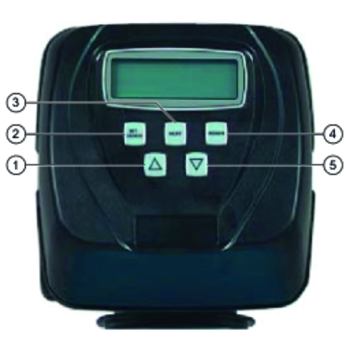
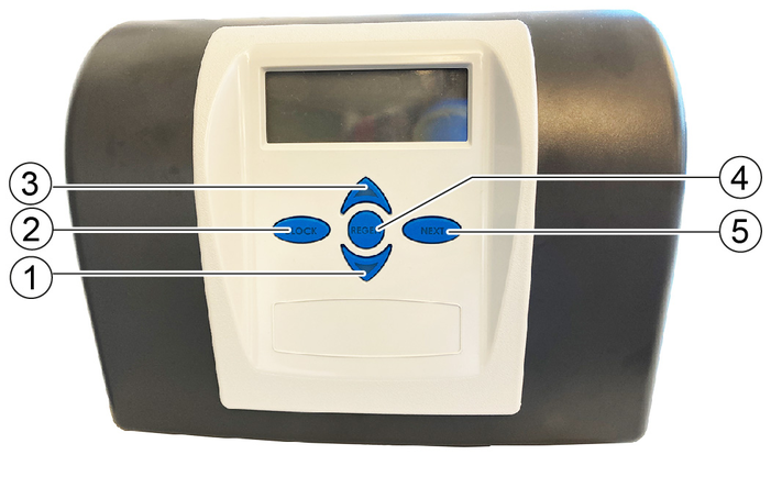
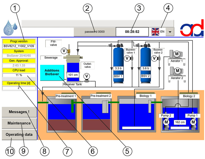
The display is located on the front of the control cabinet. The display is used for controlling the system and displaying system data.


* UTC = universal time coordinated (world time)
CET (standard time) = UTC + 1 hour
CEST (summer time) = UTC + 2 hours
The operation of the controller can optionally be authorised via a user code.
The authorisations are set up during the initial startup. Retrofitting can be carried out by customer service.
A maximum of 3 authorisations can be set up.
If the user code entry is activated, the controller can only be operated after entering the password.

Enter user code
Press the "OK" button

 |  | The unit is in auto mode and is switched on. The unit is automatically operated by the controller. |
 | 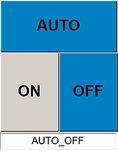 | The unit is in auto mode and is switched off. The unit is automatically operated by the controller. |
 |  | The unit is in manual mode and is switched on. The controller has no influence on the unit. |
 |  | The unit is in manual mode and is switched off. The controller has no influence on the unit. |
 | 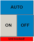 | The unit is in auto mode and has been locked due to an error. Manual mode is still possible. (See chapter Active error / info messages). |
|  | The unit is in manual mode and has been blocked due to an error. Manual mode is still possible. (See chapter Active error / info messages). |
Press the "Maintenance" button.
Scroll to the right.
Press the "Maintenance" button.
Scroll to the right.
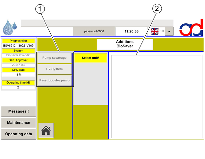
If the system is equipped with options, these are displayed and can be selected.

If no options are available on the system, possible options are greyed out and cannot be selected. No pictures are displayed.
The displayed operations data is intended for the user's information.
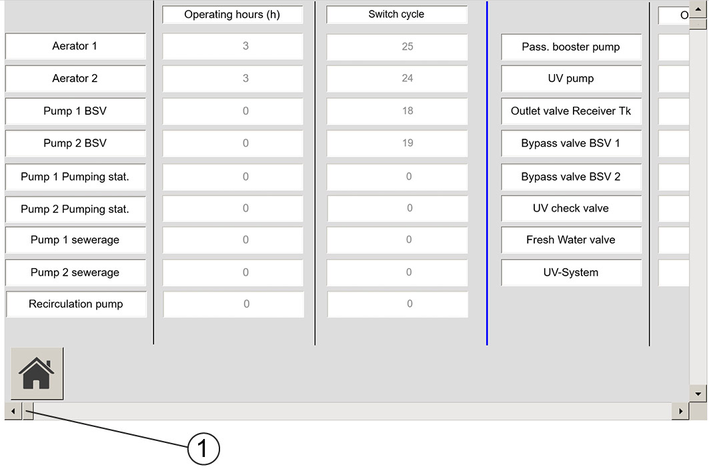
Operating hours and switching cycles are maintained by the service technician after maintenance/service and/or after replacement of the unit/component.
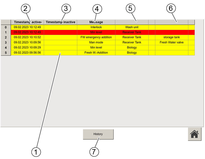
Green: Maintenance info, see Care and service
Yellow: Info message, see Resolve info message / maintenance
Red: Error message, see Troubleshooting guide
Example: On 09/02/2023 at 09:56:56, the sensor in the service water storage tank automatically activated the fresh water generation because the water level of the biological stage dropped to the specified fresh water generation level.
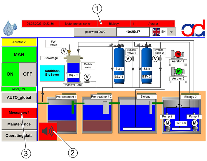
Resolve error, see Troubleshooting guide
Switch off the signal tone by pressing the signal tone button.
Press the button Messages! and check whether there are other messages within this message.
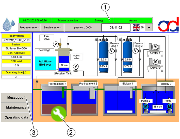
Carry out maintenance, see Care and service
Switch off the maintenance note by pressing the maintenance note button.
Press the button Messages! and check whether there are other messages within this message.
The active pressure increase system supplies the high-pressure cleaner with a constant water pressure.
The pressure switch detects the pressure reduction in the water line caused by the water removal and activates the pressure booster pump.
After the water removal is finished, the pump stops after 10 seconds after reaching the final pressure.
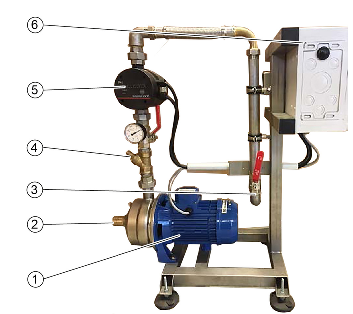
The DIP switch is set during the initial startup.
In the event of malfunctions, the red control light lights up.
Possible causes of malfunction are:
Transit time overrun
Switching cycle limit
Interruption of the voltage supply
Press the reset button to restart.
If the malfunction occurs repeatedly at short intervals, contact customer service.
The automatic insertion sieve cleaning is installed in the drain opening of the sludge trap before the first biological basin. It keeps coarse dirt particles away from the downstream system.
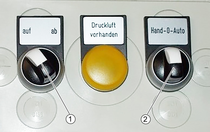
Control box of insertion sieve cleaning
In the manual mode position, the brush can be operated manually with the off/down switch.
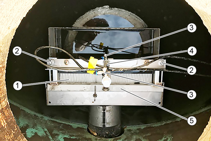
If the movement mechanism is not working to satisfaction, check the cylinder, the bearings and the cleaning brush:
Optimise the movement of the brush by adjusting the throttles on the pneumatic cylinder (standard setting, 3.5 turns is open).
Check the brushes for wear. If necessary, release the screws and adjust the brush closer to the sieve. Replace a worn or defective brush.
In the event of a defective cylinder or bearing, the entire cleaning structure can be moved upwards out of the insertion sieve box, in order to replace the defective parts.
The function of the automatic cleaning must be checked every 6 months by trained specialist personnel.
The BioSaver® / WRB Biooperates without the use of auxiliary materials or additives. Using these substances can permanently impair the biological cleaning, e.g. in emulsion splitting, ozone or filter treatment systems.
The function of the BioSaver® / WRB Bio is based on living micro-organisms that always require a certain minimum amount of oxygen. This is why the system must continuously remain in operation, also at night, on public holidays and other standstill periods of the connected washing facility.
To keep the energy requirements as low as possible, the automatic control system is programmed to independently detect the volume of incoming waste water and dynamically reduce the running time of electrical units during low load phases, such as at night, on Sundays or public holidays.
The following substances are not permitted:
Precipitants and flocculation agents
Disinfectants (also not as cleaning agent additives)
Chlorine tablets
Defoaming agents
Special care must be taken when using cleaning agents specially offered for use in recovery systems. These agents are often mixed with disinfectants, precipitants and artificial aromatic agents to compensate for known problems such as odours in recovery systems.
With the BioSaver® / WRB Bio these problems do not occur. The use of such agents is therefore pointless and questionable.
Please contact your customer service partner responsible in the case of any uncertainties or questions regarding the usability of cleaning agents.
The BioSaver® / WRB Bio can only remove biologically degradable components from the waste water, e.g. mineral oil. Many cleaning agent additives are not biologically degradable or difficult to biologically degrade and impair the waster water cleaning. Fundamentally, only cleaning agents for which the associated safety data sheets have been checked to ensure that they do not cause malfunctions in a biological waste water treatment plant may be used and these must also at least satisfy the requirements of the German Washing and Cleaning Agents Directive (WRMG). Request the manufacturer's cleaning agent data sheet in the case of uncertainties regarding selection of a cleaning agent.
Within the scope of an official inspection of your commercial premises, you are obliged to present the safety data sheets for all consumable materials used. This also includes all cleaning agents used.
Service work and repairs may only be carried out by approved customer service sites or staff qualified in this area who are familiar with all relevant safety instructions
Waste water is not a homogeneous liquid that always has the same consistency. Contact your customer service partner if the cleaning and service intervals seem to be too long. Additional cleaning and service work are no replacement for periodic inspection by technical specialists.
Risk of electric shock
The system is electrically live.
Disconnect the mains supply before working on the electrical system.
Short-circuits and other damage
The system is electrically live
Do not clean the system with a hose or high-pressure water jet.
This overview is only intended as an aid and makes no claim to completeness, especially in the case of customer-specific solutions using the BioSaver® / WRB Bio outside the specifications of the standard installation situations.
Period | Activity | Personnel |
|---|---|---|
Daily | Visual inspection for functional abnormalities on the device and control cabinet | Operator |
Weekly |
| Operator |
Monthly |
| Operator |
Half-yearly |
| Operator/Customer Service |
5-year general inspection or depending on the locally applicable legal requirements |
| Customer service / technical specialist assessor |
Presentation of the waste water processing approval | Take waste water samples and have them analysed | A laboratory approved according to the locally applicable regulations |
More information is provided in your customer-specific operator manual.
Check the sludge trap and pumping station (option) together.
The sludge level in the sludge traps must be regularly checked using a measuring disc (inspection set for separating systems). This is based on the own-monitoring directive (interval depending on the amount of sludge present). The sludge trap must be emptied by an approved disposal company when 50 % full. The disposal process can stir up sludge that can clog the coalescence separator (option) or the insertion-sieve boxes.
Fill the sludge trap with fresh water after sludge disposal to prevent a shortage of water in the system.
Check the coalescence separator (option) and the insertion-sieve boxes for soiling over a few days after sludge disposal.
Check the sludge trap and pumping station (option) together.
If necessary, drain and clean the pumping station:
Set the pumping station pump to Manual mode/Off.
Have the pumping station drained by an approved disposal company.
Remove any deposits from the pumping station if present.
Fill the pumping station with fresh water until the pumping station pumps are covered.
Set the system into Automatic mode.
The insertion-sieve box consists of the insertion sieve and the baffle plate/immersion wall. The insertion-sieve box is installed in the discharge channel of the sludge trap upstream of the 1st biological basin and protects the immersion pump from coarse dirt particles. The insertion-sieve box must be checked weekly for soiling during operation in order to prevent water from backing up in the sludge trap.
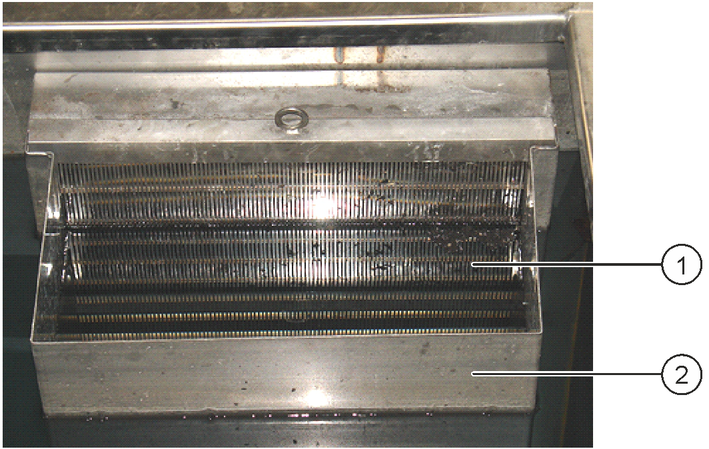
Pull the insertion-sieve box out of the shaft and set it down on a suitable surface.
Clean the insertion-sieve box with a brush.
Depending on the flow volume, the aeration device(s) of the biological stage(s) should be checked after 12 to 24 months for deposit formation and sedimentation. This work should be carried out by customer service, and at the same time as the disposal of the pre-sludge trap. Please contact your relevant customer service partner.
No processed water for the washing process is provided during the flushing period. Cleaning may only be performed when no washing operations are being performed.
The display shows an information message when the post-treatment stage needs to be flushed.
Press the button Maintenance BioSaver.

The button turns green.
The flush is triggered automatically.
After the flush is complete, the button turns grey again.
The counter for the time until the next maintenance is updated.
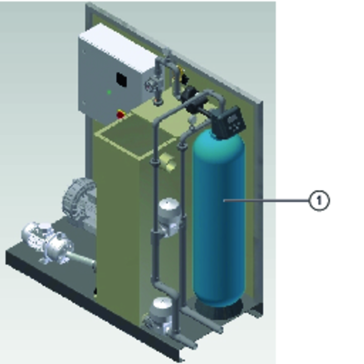
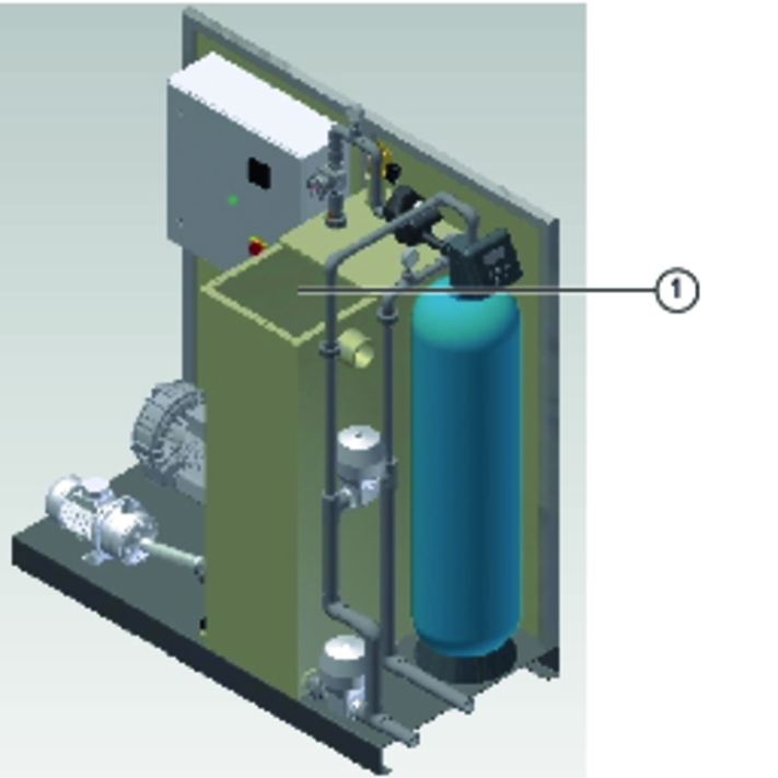
If maintenance/cleaning of the processed water supply is necessary, this is indicated by the yellow information message "Maintenance due Receiver Tank" in the status display of the control overview. No processed water for the washing process is provided during the maintenance period. Only perform the cleaning outside of the washing times. During maintenance, the yellow information message "Maintenance active" is shown in the status display. Maintenance times on the tank lead to locking of the supply. Therefore, stop washing during maintenance/cleaning! After completing the maintenance/cleaning, be sure to check the filling of the tank.
Press the "Maintenance Rec. tank" button in the "Maintenance" screen.
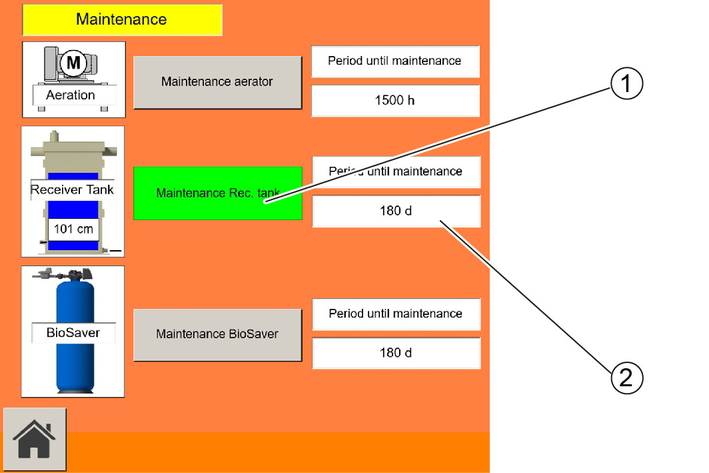
The button turns green.
The Immersion pump in the biological stage is locked.
The processed water reservoir is emptied automatically.
Carry out the maintenance work.
After the maintenance work has been carried out, press the button Maintenance Rec. tank again to confirm.
The button turns grey.
The counter for the time until the next maintenance is updated.
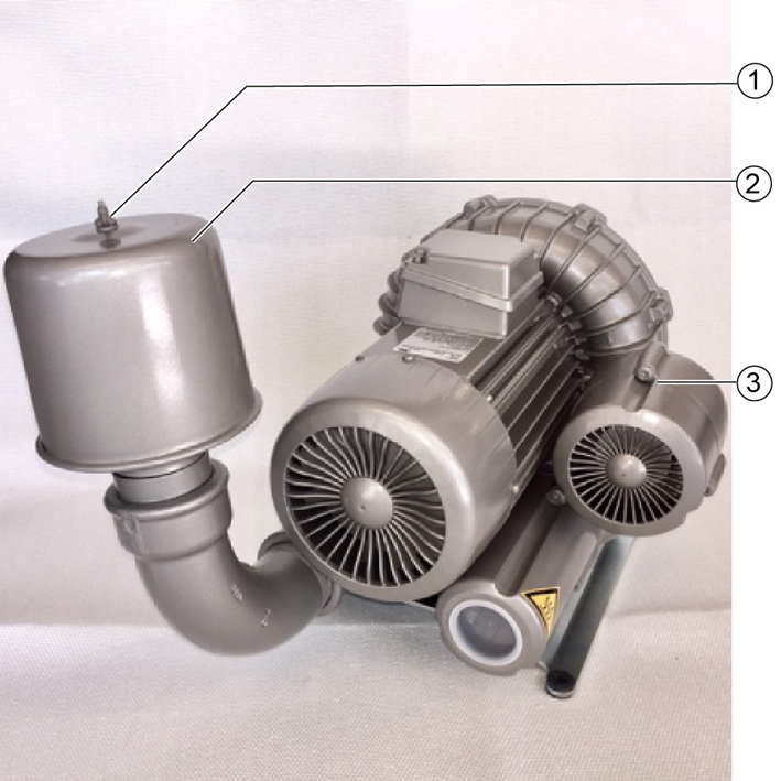
Each aerator is fitted with an intake air filter that must be cleaned at the specified intervals. The current cleaning interval is shown on the display. The intervals may need to be shortened in the case of very dirty ambient air. The interval display jumps back to the specified default interval after each cleaning.
The display shows an information message when the aerator needs to be cleaned.
Press the "Maintenance aerator" button in the "Maintenance" screen.
The maintenance mode screen opens.

Remove the wing nuts from the air filter protective hood.
Remove the protective hood upwards.
Pull off the filter cartridge.
Clean the inside of the protective hood.
Fit the new filter cartridge.
Put on the protective hood.
Ensure that the sealing ring is fitted properly.
Screw on the wing nuts and tighten.
Dispose of the filter cartridge as residual waste.
To confirm, press the button Maintenance aerator again.
The button turns grey.
The counter for the time until the next maintenance is updated.
The control system monitors the filling levels in the system tanks using special sensors.
The measuring head is sensitive to impacts. Handle it with care.
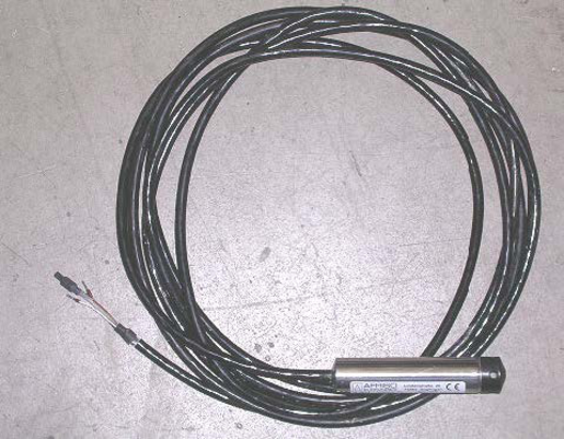
Check the pressure sensor for soiling every 4-6 months and clean carefully with a weak water jet if necessary.
The float sensor is used for overflow protection in above-ground tanks.
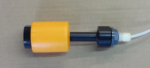
Check the float sensor for soiling every 4-6 months and clean carefully with a weak water jet if necessary.
An information/malfunction message is shown on the control cabinet display. Information on operation of the system and assistance in fault correction is provided in the following table.
Contact the service personnel if a malfunction cannot be corrected using this table.
Information message | Cause |
|---|---|
Min levelContainer | The tank has reached its lowest filling level. |
Man mode Unit | The unit is in Manual mode. |
Maintenance due Unit | The specified unit is due for service. |
Maintenance active Unit | The specified unit is in maintenance mode. |
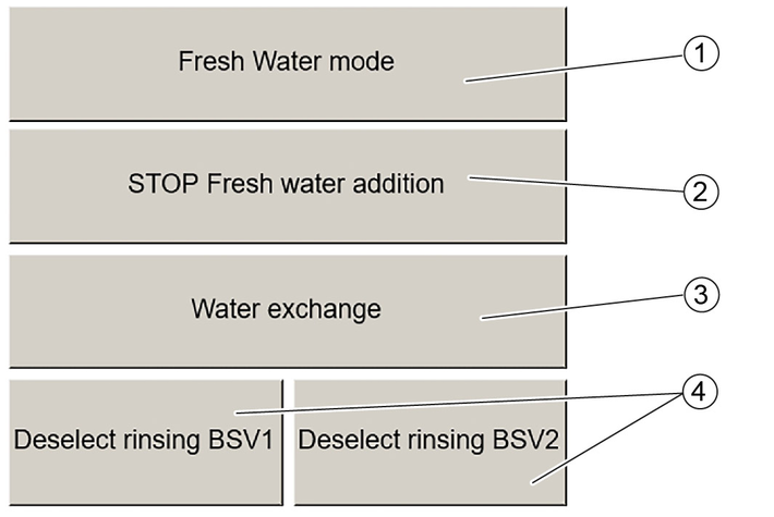
desel.Rinsing mode BSV1/BSV2 | The flushing mode of the BSV has been deactivated (for service purposes) (see chapter Fresh water operation/generation). |
Fresh W.-Addition | The fresh water injection to supplement water loss in the system is active. |
Water exchange | A water exchange is taking place in the water removal tank. |
Fresh Water mode | The Fresh water mode is active. |
Interlock | The washing facility has been locked down due to a severe malfunction. |
Rinsing mode | The Biosaver® is in flush mode. |
Failure Water meter | The counter of the water meter is not running. Check cause. |
FW emergency addition Receiver Tank | The emergency feed of fresh water into the supply tank is active. Check cause. |
Contactor exchange | The wear limit has been reached. It is recommended to replace the said element. |
Membrane exchange | |
exchange Fresh Water valve | |
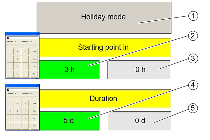
Holiday mode | The lowering of the ventilation mode is active (economy mode). |
Restart System | The system was restarted. |
Messages confirmed as completed are automatically saved in the archive. The last one hundred messages can be viewed. Older messages are discarded.
To call up the archive, see chapter Active error / info messages

Cause:
Overload of an electrical unit.
Remedy:
Activate the motor protection circuit breaker.
If this is unsuccessful then contact the Service agency responsible.
Cause:
The control air supply to the control cabinet has failed.
Remedy:
Search for the cause of the absent compressed air supply.
Min level-Tank
Cause:
The tank has reached its minimum filling level.
Remedy:
Contact customer service to determine the possible cause of the min. filling level.
buttom-Tank
Cause:
The tank has reached its maximum filling level.
Remedy:
Contact customer service to determine the possible cause of the overfilling of the tank.
Cause:
The sensor used for measuring the level / pH / conductivity has a malfunction.
Remedy:
Contact the service agency responsible.
Cause:
The max. level of the fill level sensor is safeguarded by an additional floating sensor.
Remedy:
Check the sensors.
Check the pumps.
Cause:
The water meter counter is running although the fresh water valve is not activated.
Remedy:
Check the fresh water valve to prevent unnecessary fresh water consumption.
Cause:
The FW valve has reached its maximum permissible opening time.
Remedy:
Check the level in the BWV tank.
Contact customer service to determine the possible cause.
Cause:
The aerators are in manual off mode for more than 5 hours.
Remedy:
Put the aerators back into auto mode.
Cause:
The flush has not been activated for more than 48 hours.
Remedy:
Contact customer service to determine the possible cause.
Cause:
The control cabinet of the UV system indicates a malfunction.
Remedy:
Search for the cause of the malfunction at the control cabinet for the UV system.
Contact customer service to determine the possible cause.
Cause:
The charge state of the battery is 0 %.
Remedy:
Replace the battery.
All stored data is lost if a controller with a faulty battery is switched off.
Cause:
The immersion pump no longer provides the necessary pressure for operating the system.
Remedy:
Contact the service agency responsible.
Cause:
Too much oil is present in the sludge trap (oil layer).
Remedy:
Have the oil layer disposed of by an approved disposal company.
The processed water is cloudy despite no malfunction messages on the device
.Remedy:
Check the cleaning agents for biological compatibility and correct dosage. Contact the service agency responsible regarding this.
Check that the fresh water injection has been set to 20-25 l fresh water per vehicle. Contact the manufacturer of the washing facility regarding this.
Check if servicing of the tank is due and perform this if necessary.
Water backing up in the sludge trap
.Remedy:
Clean the insertion-sieve box (see ChapterInsertion-sieve box servicing (standard version)).
Odours are generated despite no malfunction messages on the device
.Remedy:
Check the aeration in the aeration tank. A fine bubbled, evenly distributed aeration should be visible on the surface.
Check the aerator unit and perform maintenance if necessary (see ChapterAerator servicing).
Check the aerator lines for damage that may result in a loss of air.
The
immersion pump is not pumping water into the above-ground tank, despite no malfunction messages on the device.Remedy:
Check that water is present in the sludge trap being used as a water removal tank.
Check if any pipes in the system are clogged.
Check if backwater has occurred in the sludge trap chain. In particular, the light liquid separator and coalescence separator and insertion-sieve box are to be checked (see Chapter Sludge trap servicing). If no backwater is present then have the agreed minimum fresh water injection at the last flushing operation confirmed by the manufacturer of the washing facility.
It the minimum fresh water intake volume is correct then check the sludge traps for leaks.
The system has been completely switched off.
Remedy:
Stop washing operations because only enough processed water for a single wash remains.
Odours can develop if the system is switched off for several days without draining water from the tanks.
Switch on the system.
If the system is switched on after a longer standstill period, it will take a few days before the original cleaning performance is reached. When switched on, the control system assumes control of the coordination of the system.
Acknowledge the malfunction messages and emission of the acoustic horn signal occurring in the case of insufficient water in the processed water tank.
Device performance data | |
Flow volume | 2,0 m3/h |
Voltage | 400 V |
Frequency | 50 Hz |
Power rating | 4,0 kW |
Dimensions and weights | |
Weight | 300 kg |
Length | 1000 mm |
Depth | 780 mm |
Height | 2000 mm |
Device performance data | |
Flow volume | 4,0 m3/h |
Voltage | 400 V |
Frequency | 50 Hz |
Power rating | 6,0 kW |
Dimensions and weights | |
Weight | 400 kg |
Length | 1000 mm |
Depth | 780 mm |
Height | 2000 mm |
Systems for treating and circulating waste water from vehicle washing, care and repair facilities according to General Technical Approval Z-83.1-33 from 11.11.2015.
Modelas BioCiron®-System / BioSaver®-Systemreihen
Guidelines and standards usedZ-83.1-3
2014/35/EU
2014/30/EU
EN ISO 12100
EN 60204-1
DIN VDE 0580
DIN EN 806
2011/65/EU
2015/863
aquadetox international GmbH herewith confirms that according to current knowledge all products sold by aquadetox international GmbH (if not expressly marked) comply with the directive 2011/65/EU. These products meet the current requirements of the RoHS directive for all 7 named materials: Max. 0.1% of weight in homogeneous material for lead, mercury, hexavalent chromium, polybrominated biphenyl (PBB), polybrominated diphenyl ether (PBDE), deca-BDE and max. 0.01% of the weight for cadmium.
The system may not be operated until it has been ensured that the system has been installed according to the operating manual, installation plan and assembly documentation and thus conforms to the aforementioned regulations and guidelines. The declaration is invalidated by any changes made to the product that are not approved by us.